VLSI Implementation of a Conductance-based Multi-Synapse using Switched-Capacitor Circuits Marko Noack, Markus Krause, Christian Mayr, Johannes Partzsch and Ren´e Sch¨uffny Endowed Chair for Highly Parallel VLSI Systems and Neuromorphic Circuits Institute of Circuits and Systems, Technische Universit¨at Dresden, Germany Email:
[email protected] Abstract—For neuromorphic ICs, the implemented synaptic dynamics play an important role in the complexity achievable when running networks on the overall IC. One of these ingredients for realistic dynamics are conductance-based synapses, which in contrast to current-based synapses let a neuron adapt in various ways to its input characteristics. Another ingredient is classical neuronal spike-frequency adaptation. Both are usually realized in fully-analog subthreshold circuits, making them hard to port to modern sub-100nm technologies. In contrast, we present a compact switched-capacitor (SC) model of a conductancebased synapse that can be widely configured to accurately depict e.g. NMDA, GABA or AMPA type synapses. The SC approach is inherently easy to port between technologies and its digital part benefits fully from technology scaling. We show how this synapse circuit can also be utilized to endow a neuron with spikefrequency adaptation (SFA). Keywords—conductance-based, multi-synapse, spike-frequency adaptation, switched-capacitor, neuromorphic
I.
I NTRODUCTION
In order to support the advancing knowledge in the field of neuroscience, state-of-the-art neuromorphic circuits must provide biologically realistic behavior, incorporating e.g. conductance-based synapses [1], exponentially decaying conductance trace and dynamic behavior such as SFA and voltage dependent synaptic responses (e.g. NMDA-type synapses). Most analog implementations of neuromorphic circuits rely on so-called subthreshold circuits. These are hard to port to small CMOS techologies, since leakage currents rapidly increase with down-scaling, reaching the range of the desired signal currents. Additionally, device mismatch and process variation increase and the range of transistor transfer functions usable for computation is very limited. This is why even recent neuromorphic systems have been manufactured in quite large technologies [2]–[4]. Furthermore, significant deviations caused by device mismatch and process variation have to be expected even there, so control voltages have to be adjusted very accurately. On the other hand, due to relatively high current ranges analog neuromorphic circuits exploiting MOS transistors in saturation [5] mostly suffer from realtime capability, which is important for e.g. interfacing living nerve tissue and processing real-world input stimuli. These problems can be largely circumvented by using SC circuits [6], [7], which utilize robust charge-based signal transmission and offer a wide-range configurability. Due to the mixedsignal approach with a relatively large digital circuitry for controlling the analog circuit, they can be ported easily to small technologies, since only standard building blocks like opamps, switches and capacitors are required. This again allows a high
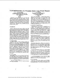
Fig. 1. Leaky integrate-and-fire neuron with different types of conductancebased multi-synapses and spike-frequency adaptation.
accuracy of the reproduction of biologically realistic behavior [8]. In this paper we present a mixed-signal neuromorphic system with SC synapses and a digital circuitry calculating the conductance value of high input count multi-synapses, consisting of standard analog building blocks and synthesizable digital logic. We describe circuit techniques to reduce leakage currents for achieving higher time constants. Additionally, we present an approximation to the nonlinear voltage dependence of NMDA synapses that simplifies circuit implementation, while closely matching the exact formulation in the relevant voltage range. II.
C IRCUIT D ESCRIPTION
The circuit models a leaky integrate-and-fire neuron [9] with SFA and several types of conductance based multisynapses (see Fig. 1). The synaptic current of each type is Isyn,i = gsyn,i (Esyn,i − Vm ) ,
(1)
with membrane voltage Vm , reversal potential Esyn,i and the synaptic conductance gsyn,i modeled by X dgsyn,i −gsyn,i + ∆gsyn,i = wk δ(t − tk ) . (2) dt τsyn,i k
This results in an exponentially decaying conductance with the corresponding time constant τsyn and with instantaneous increments depending on a global conductance change ∆gsyn,i and a specific weight wk at each incoming spike k at time tk . Since different weights can be applied for each spike and the resulting conductance changes sum linearly on one variable this synapse can emulate an arbitrary number of individual synapses [1], hence the name ”multi-synapse”. The circuit of the conductance-based multi-synapse makes use of a mixed signal approach, where the time-varying conductance value is stored and computed in a digital sub-circuit
Fig. 2. Principle schematic of the leaky integrator circuit emulating the synaptic conductance.
(see grey box in Fig. 1) and the membrane capacitance of the postsynaptic neuron as well as the synaptic conductance itself are represented by analog circuitry. The circuit offers several simultaneously acting synapse types, which can be configured individually for e.g. NMDA-, GABA- or AMPA-type behavior. The adjustment includes time constant, amount of conductance change at incoming spikes and the corresponding reversal potential. A. Switched-Capacitor Synapses Fig. 2 shows the principle of operation for conductancebased synapses using SC circuits. In contrast to the circuit in [6], the membrane voltage is buffered by an opamp for further computation in the NMDA circuit (described in Sec. II-E) and for monitoring. The synaptic conductance is modeled by an SC resistor emulation, consisting of Csyn and switches S1 to S4 . In combination with the parallel membrane capacitor, a leaky integrator is created. S1 , S2 and S3 , S4 , respectively, are switched alternately and non-overlapping as indicated by switch phases Φ1 and Φ2 . In phase Φ1 capacitor Csyn is precharged by the synaptic reversal potential Esyn , and in Φ2 a charge equalization on Csyn and Cm occurs. The conductance value is determined by the switching frequency fswitch and the capacitance Csyn : gsyn = Csyn · fswitch
(3)
The analog circuit realizing the leaky-integrate-and-fire neuron with multiple synapse types is shown in Fig. 3. Its fully-differential architecture has been chosen to reduce charge injection and clock feedthrough. A simple SC common-mode feedback network (not shown) controls the common-mode voltage Vcm = VDD /2. The SC resistor emulators representing the synaptic conductances are connected in parallel to the membrane capacitor. An on-chip 8 bit digital-to-analog converter provides the different reversal potentials for the corresponding synapse types. B. Leakage Current Reduction A major issue in SC circuits is leakage current through switches, particularly when moving to sub-100nm technologies. Especially for neuromorphic circuits with time constants in the milliseconds range, low switching frequencies and small capacitance values, these currents have a strong impact on the accuracy of model reproduction. A way to reduce these effects is by applying low-leakage switches as shown in [10], where
Fig. 3. SC neuron circuit with conductance-based synapses and comparator for threshold detection.
a MOS switch is split into two transistors and the middle node voltage is drawn to VDD in off-state (see upper right of Fig. 3). Simulations have shown that leakage can be further reduced by choosing a voltage between VDD and ground. In Fig. 3 this method has been applied with switches S1 – S6. S2 and S3 disconnect Cm from the opamp feedback loop. S1 and S4 set the outer nodes of the switches to a defined voltage which is equal to Vcm in this case. This reduces subthreshold currents through MOS transistors of S2 and S3 since VDS is kept low. Furthermore, subthreshold leakage currents are kept independent of the opamp output voltage. Another advantage of the proposed switch configuration is the absence of gate leakage at the opamp input which otherwise would draw current from the membrane capacitor. A reduction of junction leakage at the switches surrounding Cm can be achieved by minimally sized drain and source areas. In order to effectively exploit this low leakage technique, the membrane capacitor is decoupled from the circuit whenever none of the synapse, SFA or leakage generation circuits is in its second switch phase Φ2 , where Csyn is connected to Cm . In this state S5 and S6 disconnect the opamp from the rest of the circuit and S7 closes a negative feedback loop around the opamp, which prevents the opamp outputs from floating towards supply rails. C. Digital Generation of the Conductance Trace Eq. (2) is implemented by the digital circuit shown in Fig. 4. Its main parts are the conductance trace generation and a numerical-to-frequency conversion, which triggers the switch event generation for the SC circuit. The conductance trace generation sub-circuit holds a register GSYN REG, which stores the conductance value. If a spike arrives, meaning VALID is high for one clock cycle, the weight of this spike is added to GSYN REG. Between incoming spikes the conductance value decays exponentially towards zero. This is done by subtracting the value of GSYN REG shifted right by 6 bit, which results in a multiplication by 1 − 2−6 = 0.984375, in a constant interval configured by TAU SYN. TAU COUNTER is incremented at each system clock cycle and when it reaches TAU SYN it is reset and the subtraction is done. This leads to a direct proportionality between the synaptic time constant and the configuration value τsyn = −T AU SY N/(fclk ·log(1−2−6 )).
Fig. 5. Linear approximation of the voltage dependence of NMDA-type synapses. Fig. 4.
Block diagram of the digital circuitry.
In the second part, the conductance is accumulated on the phase register PHASE REG, which is clocked analogously to GSYN REG. When an overflow is detected by the adder the two switch phases for the analog part of the synapse are triggered. With this method, the value of GSYN REG is converted linearly to the switching frequency. Scaling of the frequency can be done with DELTA GSYN, which is inversely proportional to the conductance change ∆gsyn,i in Eq. (2). D. Modeling SFA with Conductance-based Multi-synapses A phenomenon especially present in pyramidal cells is SFA. As shown in [9], it can be modeled in a similar way as the conductance of a multi-synapse with a certain reversal potential Esf a , where gsf a tends to shunt the membrane capacitance dependent on the spiking frequency of the neuron, which decreases the neuron’s excitability. For this, a fixed amount is added to gsf a at each post-synaptic spike. In our implementation, the same synapse circuit can be used for SFA with only minor modifications. The spike output of the neuron has to be connected to the spike input of the SFA circuit and the WEIGHT signal can be set to a fixed value, e.g. 1.
Fig. 6. SC circuit providing the membrane voltage dependent reversal potential for NMDA synapses.
The circuit generating the voltage-dependent reversal potential is depicted in Fig. 6. In the sampling phase Φ1 , the membrane potential is stored on the binary weighted capacitors C1-C3 corresponding to α, and on C4, whereas C5 is reset. In Φ2 , ∗ the fraction α of Vm − Enmda is integrated on C5 and the output voltage is shifted by Vm , resulting in an output voltage as described in Eq. (6).
E. Modeling NMDA-Type Synapses In contrast to other synapse types, NMDA synapses show a dependence between conductance value and membrane potential [9]. The synaptic current of NMDA-type synapses can be modeled by Inmda = gnmda0
(Enmda − Vm ) , Vm 1 + 0.28 · exp( 16.129 mV )
(4)
with Enmda = 0. The nonlinear dependence of the conductance on Vm is difficult to faithfully reproduce in a circuit implementation. As can be seen in Fig. 5, this dependence can be well approximated linearly in the range between lowest reversal potential at about −70 mV for inhibitory synapses and threshold voltage at about −50 mV: ∗ ∗ Inmda /gnmda0 = α(Vm − Enmda ).
(5)
We can rewrite Eq. (5) to get a regular conductance-based ∗ synapse Inmda = gnmda0 ·(Ex −Vm ), with a voltage-dependent reversal potential ∗ Ex = Vm + α(Vm − Enmda ).
(6)
III.
R ESULTS
The neuromorphic system was designed in a 180 nm CMOS technology with a supply voltage of 1.8 V. A neuron circuit including one NMDA circuit has a power consumption of 45 µW and a total silicon area of 18 000 µm2 . The digital circuit consumes an area of 45 000 µm2 for one neuron with 5 synapse types and has a power consumption of approximately 100 µW. Sources of deviations from the ideal model parameters are opamp non-idealities, capacitor mismatch and leakage currents. Due to the differential voltage swing of 1.5 V, the opamp offset voltage of less than 10 mV is negligible. Capacitor mismatch has an effect on the membrane time constant and conductance values of the synapses, but can be compensated by digital configuration. Unfortunately, we are not provided with Monte-Carlo simulation models for the MIM capacitors we used, so only a nominal simulation has been carried out. Simulation results are depicted in Fig 7. The upper diagram shows the membrane voltage trace Vm . At 1 ms, the neuron is stimulated with a 10 kHz spike train for 10 ms arriving at an AMPA synapse with high reversal
IV.
C ONCLUSION
We presented a conductance-based high input count multisynapse using SC circuits. With a slight modification, the circuit can be used to model SFA. Furthermore, it has been shown how the voltage dependent behavior of NMDA-type synapses can be implemented with additional circuitry. The overall silicon area of the neuron is 63 000 µm2 and consumes less than 100 µW of power. Due to a large capacitance array consisting of unity capacitors of 50 fF (100 µm2 ), a fullydifferential architecture and a dedicated low-leakage technique, a high model accuracy is achieved compared to existing subthreshold circuits [2] and SC implementations [6]. Since the area is strongly dominated by MIM capacitors, it could be shrunk with relaxing the accuracy requirements. The large digital part would perfectly benefit from technology scaling. In contrast to [6], our circuit is equipped with exponentially decaying conductances and is designed to emulate up to 10k synaptic inputs at a firing rate of 10 Hz providing a biologically realistic behavior. Fig. 7. Simulation results of membrane potential with synaptic input from three different synapse types.
potential and τampa = 2 ms. At 30 ms, an inhibitory GABA spike is triggered (τgaba = 10 ms), which decreases the membrane potential. From 40 ms to 70 ms, a 1 kHz spike train arrives at the NMDA synapse (τnmda = 100 ms). The supra-linear increase of the membrane potential indicates the voltage dependence of NMDA-type synapses (see Eq. (6)). After reaching the threshold voltage at about 90 ms the neuron fires and is reset to its reset voltage. Our implementation focuses on a robust reproduction of the model equations and a high number of synaptic inputs, which are required e.g. when simulating population bursts [11]. Other implementations of conductance-based synapses may consume less area, but at the cost of reduced functionality and robustness. A subthreshold circuit of a conductance-based synapse with NMDA behavior is presented in [2]. The synapse circuit was designed in a 0.35 µm process and consumes an area of 1360 µm2 . While this circuit was designed as a single synapse, it could be used as multi-synapse as well, by discarding the short-term plasticity mechanism. However, it is not able to support such a high input count as our implementation. Furthermore, due to the exponential dependence between control voltage and current signals, synaptic behavior is very sensitive to device mismatch and process variation. Another implementation of a conductance-based multisynapse using SC circuits can be found in [6]. It was fabricated in a 0.5 µm process where a neuron circuit with one multisynapse consumes an area of about 3700 µm2 . Here each incoming pulse event triggers a switch event, which transmits a charge packet. Although this is a very flexible approach, exponentially decaying conductance traces and summation over synapses have to be generated off-chip. In contrast, these features are an important part of our integrated implementation. As an outlook, memristive technologies could profit from our circuit principle: By connecting the memristor terminals to the postsynaptic membrane and a pulsed voltage source driven by the switch event generation circuit, learning memristive arrays [12] could be equipped with conductance-based synapses.
ACKNOWLEDGMENT This research has received funding from the European Union Seventh Framework Programme (FP7/2007- 2013) under grant agreement no. 269459 (CORONET) R EFERENCES [1] A. Destexhe, Z. F. Mainen, and T. J. Sejnowski, Methods in Neuronal Modeling, 2nd ed. MIT Press, Cambridge, MA, 1998, ch. Kinetic Models of Synaptic Transmission, pp. 1–25. [2] C. Bartolozzi and G. Indiveri, “Synaptic dynamics in analog VLSI,” Neural Computation, vol. 19, no. 10, pp. 2581–2603, 2007. [3] G. Indiveri, F. Stefanini, and E. Chicca, “Spike-based learning with a generalized integrate and fire silicon neuron,” in ISCAS. IEEE, 2010, pp. 1951–1954. [4] S. Moradi and G. Indiveri, “An event-based neural network architecture with an asynchronous programmable synaptic memory,” TBioCAS, pp. 1–10, March 2013. [5] M. Noack, J. Partzsch, C. Mayr, S. Henker, and R. Schuffny, “Biologyderived synaptic dynamics and optimized system architecture for neuromorphic hardware,” in MIXDES, 2010, pp. 219–224. [6] R. J. Vogelstein, U. Mallik, J. T. Vogelstein, and G. Cauwenberghs, “Dynamically reconfigurable silicon array of spiking neurons with conductance-based synapses,” IEEE TNN, vol. 18, no. 1, pp. 253–265, 2007. [7] F. Folowosele, A. Harrison, A. Cassidy, A. Andreou, R. EtienneCummings, S. Mihalas, E. Niebur, and T. Hamilton, “A switched capacitor implementation of the generalized linear integrate-and-fire neuron,” in ISCAS, 2009, pp. 2149–2152. [8] M. Noack, C. Mayr, J. Partzsch, M. Schultz, and R. Sch¨uffny, “A switched-capacitor implementation of short-term synaptic dynamics,” in MIXDES, 2012, pp. 214–218. [9] E. T. Rolls and G. Deco, The noisy brain: stochastic dynamics as a principle of brain function. Oxford university press New York, 2010, vol. 28. [10] G. Ellguth, C. Mayr, S. Henker, R. Sch¨uffny, and U. Ramacher, “Design techniques for deep submicron CMOS / Case study Delta-SigmaModulator,” DASS, pp. 35–40, 2006. [11] T. Masquelier and G. Deco, “Network bursting dynamics in excitatory cortical neuron cultures results from the combination of different adaptive mechanisms,” PLoS ONE, vol. 8, no. 10, p. e75824, 10 2013. [12] C. Mayr, P. St¨arke, J. Partzsch, L. Cederstroem, R. Sch¨uffny, Y. Shuai, N. Du, and H. Schmidt, “Waveform driven plasticity in BiFeO3 memristive devices: Model and implementation,” in NIPS, 2012, pp. 1700– 1708.