The host-processor interface bus is bidirectional of width 8 bits so that the chip .... The router has been designed as a general purpose one, and is capable of ...
VLSI Implementation of a Wormhole Router Using- Virtual Channels A. S h y a m Prakash' Cadence Design Systems (India) pvt. Ltd. SDF#A-l/B-8, Noida Export P m e s i n g Noida, 201305, U.P. INDIA Abstract In this paper, we present the V U 1 design of a router chip which implements wormhole routing using virtual channels. The router chip is intended for high-speed interconnection network in parallel processors, and is capable of handling any interconnection network which is achieved by providing the routingfwrction as a RAM based look up table. The architectural description of the chip is provided. The behavioral description of the chip is made using Verilog HDL. Finally the chip is implemented using the standard-cell design automation package, OASIS.
-
zone.
1 Introduction Massively parallel processing systems which use over 4000 processors are being conceived for achieving teraflops performance needed in addressing grand challenge problems. Such machines are built as distributed memory multiprocessors, since it is difficult and inefficient to build them as shared memory computers. As a result, data sharing among processors must take place through message passing. Efficient interprocessor communication is therefore a necessity in massively parallel computers. It is not possible to use the complete graph topology in massively parallel machines due to the excessive hardware cost and interconnection complexity that would involve. Usually some structured way of interconnection with minimum number of links is used. If a message is to be sent from one node to another which are not directly connected to each other, the message is routed by forwarding it through intermediate nodes. 1.1 Wormhole Routing
In wormhole routing [2], a packet is divided into smaller units calledflits (flow control digits). The packet is broken down into one header flit, one or more &fa pits, and a tail pit. Only the header flit contains the destination address; therefore, it is the header flit which governs the route, and the remaining flits follow the header flit in a pipehed fashion. The decision about the route can be made as soon as t..- header flit is available, hence the time taken by the packet to reach destination is considerably reduced. An output channel is allocated to a packet rather than a flit. If the packet size is large enough, the time taken for transmission will depend mainly upon the number of flits transmitted and hence becomes independent of the distance between source and destination. It can also be seen that if a channel gets blocked, it is required to buffer only a tiit; hence the amount of buffer space required at the node is very mall [21. 1.2 Virtual Channels
When wormhole routing is employed, the header flit gets blocked if the output channel is already assigned any other packet. Since only the header flit has the destination address, all the remaining flits must wait in their channels until the header flit can make progress. The physical channels used by any of these blocked flits cannot be 'This work was canied out when author was an M.Tech Student at EE Department. I n Delhi.
C.P. Ravikumar Department of Electrical Engineering Indian Institute of Technology New Delhi 110016 INDIA used to route another packet. A solution for this problem is suggested by Dally [3], which is to use virtual channels. In this solution, many virtual channels are multiplexed on to a single physical channel. Thus, even if a virtual channel gets blocked, other virtual channels can make use of this physical channel and we make higher utilization of the physical resources. Virmal channels are implemented by allocating separate buffers for each virtual channel; these buffers are connected to the physical channels through multiplexers and demultiplexers. Virtual channels also allow one to introduce deadlock free routing [4].
1.3 Motivation for Hardware Routers Considerable amount of processing must be performed as part of a routing. This processing involve the decomposition and reassembly of the message, the application of the routing function to determine the output channel along which the flit must be forwarded, copying the flit into a flit buffer, book-keeping activities to maintain the status of the current node and that of the next node. A software simulation of a wormhole router implemented at IIT Delhi [IO] uses about 2000 lines of C code. Since routing is one of the primitive functions in a multiprocessor environment, it is desirable that it is as fast as possible. This motivates us to develop hardware routers. 1.4 Earlier Hardware Routers
While much work has been reported in the literature on the simulation and performance analysis of different routing techniques [2,3,41, very few attempts have been made to implement these routing algorithms in hardware. Three notable contributions in this direction are (1) The Message Driven Processor [ 5 ] , (2) The Mad-Postman network chip [6],and (3) Hardwxe kouter tor Star Graph [9]. The Message Driven Processor (MDP) has been designed by a research group at MIT [5] and has been used in a parallel computer built by the same group. The parallel processor is called J-machine and is based on the k-ary n-cube topology[2]. The MDP is designed as an instruction set processor and is hence very flexible. But it cannot operate at high speeds due to the overhead of instruction fetch and decoding. In the Mad-Postman network chip, the latency is reduced by taking the concept of flits to an extreme; here, flits are I-bit long. Thus, when a header bit is received by a node, it cannot fully determine whether the flit is intended for itself or if it must be forwarded. The forwarding process continues until enough bits have been received to decipher the destination of the message. The Mad-Postman chip has been implemented for a two dimensional mesh topology. In [9]. the authors implemented the Akers-Krishnamurthy routing algorithm for Star Graphs [7] in hardware; however, they did not consider the other overheads in the routing algorithm. 1.5 Aim of this Work In our design of the router chip, emphasis is given to implement wormhole routing using vinual channels. The router is not specific to any particular topology; it is provided with a programmable look-
1035
Authorized licensed use limited to: IEEE Xplore. Downloaded on October 29, 2008 at 11:57 from IEEE Xplore. Restrictions apply.
up table to implement the routing function. For each physical link, a separate receiver and transmitter module is used to enable simultaneous transmission and reception. In the following section, we describe the architecture of the router chip and the behavior modeling of the router using Verilog hardware description language. In Section 3, we discuss the hardware design of the muter and its implementation using OASIS standard-cell design automation package. Section 4 presents the results and conclusions.
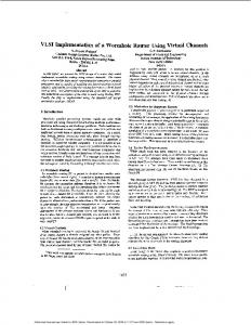
2 Architecture of Router Chip The architecture of the proposed router chip is described here. A careful examination of the routing process reveals that there are four important subtasks involved: (1) Receiving flits from a neighboring node, (2) Transmitting flits to a neighboring node, (3) Deciding the virtual channel along which a flit must be forwarded, (4) Host-processor Interface, involving assembling of flits into messages and vice versa. We have organized the router chip into four major blocks, one corresponding to each of the subtasks mentioned above. The block diaeram of the router chiD is shown in Fieure 1. We now describe
2.2 Transmitter block There is one transmitter block per physical channel. The operation of the transmitter block is captured below using pseudocode. forever do parbegin for each virtual channel vc do if vc has been assigned to a packet and
vc is not in blocked state and a flit f is available in corresponding fit-huffer then begin transmit the flit A iff is a tail-Kit then cancel mapping of vc; mark vc to be in blocked state; end; if a handshake i s received then begin receive virtual channel number vc; release vc from blocked state:
end; parend; The transmitter block multiplexes N,, virtual channels to a single physical channel in a round robin fashion. The mapping from the virtual channels to the flit-buffers is done by the channel allocator block described next. The transmitter uses this mapping to associate a particular flit-buffer with each of its virtual channels. If a flit is present in the buffer corresponding to a virtual channel vc, then the flit is picked up for transmission. After flit has been transmitted, another flit can be transmitted through the virtual channel vc only after a handshake signal has been received, signifying that the neighbor node is ready to receive the next flit through vc.
2.3 Channel Allocator
I
I
I
I I
I
Figure 1 : Block Diagram of Router Chip
the function of each of the individual blocks of the router. A detailed description of the design of each of these blocks is provided in Section 3. 2.1 Receiver block
One receiver block is present for each physical channel. The behavior of the receiver block is given below in pseudocode. forever do parbegin begin wait for start bits; receive virtual channel number vc; receive flit 2 Place flit f in buffer vc; end if a flit-buffer has been emptied then send handshake signal to neighbor; parend The receiver block has N,, flit-buffers, where N,, is the number of virtual channels supported per physical channel. Each of these flit-buffers is capable of storing NFflits. The receiver block uses a control logic (see Section 3) to continuously monitor the input physical channel for incoming start bits. The receiver block concurrently monitors the status of its flit-buffers; if any one of these flit-buffersfb has been emptied (by the transmitter block, as will be seen later) the receiver must send a handshake signal to indicate it is ready to receive the next flit of the virtual channelfb.
There is one channel allocator per node. The functional behavior of the allocator can be described using the pseudocode shown below. forever do for each flit-buffer b do if b contains a headerflit h then begin if output_chnnnef[route(h.destination)l is not currently mapped to any flit-buffer then map b to outpur-channef[route(h.destination)]; end; This module assigns the output channel through which a sequence of flits belonging to a packet should be routed. This decision is made when a header flit arrives in any of the flit buffers. The mapping of flit-buffers to virtual channels is implemented by the routing function,which is specific to the interconnection network being implemented. In this design, the mapping has been implemented through a RAM-based lookup table, allowing a significant degree of flexibility. The router table is initialized by the host processor whenever the system is reset. The routing function implemented by the lookup table is of the form R :D + PC X VC, where D is the set of nodes in the network, PC is the set of physical channels, and VC is the set of virtual channels. We indicate the ordered pair of physical and virtual channel as the output channel. 2.4 Processor Interface block There is one processor interface block for each node. The functions carried out by this block are the following. (1) Upon reset, accept data from the host-processor and program the routing table (2) Accept a packet from host-processor and disassemble the packet into a header, data, and tail-flits. The flits are stored
Authorized licensed use limited to: IEEE Xplore. Downloaded on October 29, 2008 at 11:57 from IEEE Xplore. Restrictions apply.
(3)
as well as handshake.
in a flit-buffer one by one. Assemble the flits destined to the current node into packets and forward them to the host-processor.
2.5 Behavioral Description using Verilog The behavioral description of the muter chip was carried out using the Verilog Hardware Description Language [ 1I]. The flit buffers, packet buffers and the routing table. which have to store data, are declared as array of registers. Other parameters like status information for each virtual channel, are also defined using register variables. The physical links are defined as separate input and output variables. The bidirectional interface to the host processor is implemented using the inout type variables. Since the Verilog does not support the declaration of multidimensional arrays, it is required to write separate tasks for each physical channel, even though all the transmitters and receivers are identical. Separate tasks were written for handshake transmission and reception. The functional block processor interface is described as three different tasks for receiving, transmitting packets and for initializing the routing table. All these tasks are combined to form a module with parameters which form the interconnection pins of the chip. By instantiating this module as many times as the number of nodes that are required, any network can be formed. The program is written in such a way that any modification, if required, can be done with very little effort.
3 Hardware Router Design 3.1 Design Specifications The host-processor interface bus is bidirectional of width 8 bits so that the chip can be interfaced with any commercial processor. In this design, the packet size is limited only by the buffer size that can be supported by the target implementation. For example, if FPGAs are used to implement the router chip, it will be difficult to support a large number of buffers on-chip. Here the packet size has been chosen to be 40 bytes, which is sufficient for a parallel processing system to transfer data at a high rate.
Eight bits are used to represent node addresses. Once again, these many bits suffice for a number of interconnection networks such as 3-D hypercube, 3-D mesh, and 4-star. The routing table can store output channel numbers for all the 256 possible addresses. Each routing table entry contains the output physical channel and the virtual channel numbers.
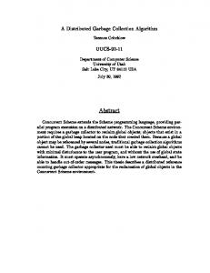
3.2 Protocol for communication All the blocks in the router chip operate at a base clock frequency. The baud rate of data transmission over the links is set to one fourth the base clock frequency. This strategy will assure proper communication if the nodes are operating asynchronously, provided the clock frequencies are same for all nodes. When a flit is to be transmitted, first two start bits are sent, followed by the virtual channel number, the flit type (header, data or tail), and information bits (see Figure 2a). The handshake signalling consists of a start bit followed by the virtual channel number in a bit-serial fashion.
In order to interface with the local processor the control signals provided are Reset, Chip-select, Read, Write, Bfr-empty, and Pkt-ready. The Chip-select signal must be enabled for the router chip to be accessible to the host-processor. Reset will initialize the chip and cause the routing table to be reprogrammed. The Pkt-ready signal indicates to the host that a packet has arrived in the router, which can be read word by word using the Read line. The
Data Transmission
Handshake
(4
The flit size should be as small as possible so that the time taken for its transmission is reduced; at the same time, other overheads such as the virtual channel number and the flit-type should not dominate the size of the data field. In the design, the flit size is taken as 20 bits, inclusive of 2 bits for virtual channel number and 2 bits for flit type specification. Thus, each flit carries 2 bytes of information. ’
Currently, the number of physical channels provided are 3, since this will enable us to implement a variety of interconnection networks, such as a 3-D hypercube, Cube Connected Cycles, 4-star, 3-D mesh, and so on. Simulation results [3] have shown that as the number of virtual channels is increased. the network throughput saturates. It was observed in [3] that the number of virtual channels are in the range from 3 to 5 gives a better throughput to cost ratio. In this chip, 3 virtual channels are provided per physical channel. If the number of lines per physical link is increased, the transmission rate increases; but at the same time, the implementation cost goes up. On the other hand if the number of lines is reduced, it will increase the transmission time. In our design, two lines per physical channel are provided since it makes design of internal modules easy. Only one line is used for handshake. Separate connections are used for either direction, for both data transmission
Data Reception (a)
Figure 2 : Protocol for (a) Transmission (b) Reception Bfr-empty signal indicates to the host that the router is ready to accept the next packet for transmission. The host can write one word by enabling Write line and placing the appropriate data on the host-processor interface bus.
3.3 Design of functional modules In the chip, buffers a& implemented using shift registers. The routing table is an array of registers which can be accessed by giving the destination address. To generate the baud clock, separate modulo 4 counters are used at each transmitter and receiver modules. The design of the individual modules is now explained.
1037
Authorized licensed use limited to: IEEE Xplore. Downloaded on October 29, 2008 at 11:57 from IEEE Xplore. Restrictions apply.
met. (i) vc is assigned to a packet (ii) vc is not in the blocked state, and (iii) there is a flit available in the corresponding buffer @ for transmission through vc.
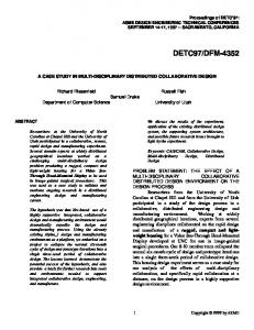
Receiver module The block diagram of the receiver module is given in Figure 3. The controller will continuously monitor the physical channel, and when it detects the start bits, it waits for half a bit duration (2 base clock pulses) and starts sampling the channel at the middle of a bit (see Figure 2b). If the first sample c o n f m that the start bits are stable, the sampling continues. The next sample gives the virtual channel number which will be stored and decoded to select the corresponding buffer. The data which follow are sampled and stored in the virtual channel buffer. These buffers can be read by the transmitter block. The f m t two bits will identify the flit type. This, along with bufferfull indication, are latched by the controller. The headerflit signal is used to enable the channel allocator. The tailflit
Transmission includes sending the start bits, the virtual channel number vc, and the data in the corresponding fit-buffer@. The f i t type and the buffer full indication of @ are reset after the transmission of the flit. At the same time, the status of vc is set to blocked state and will be reset only when the transmitter receives a handshake corresponding to vc. If the flit transmitted is a tailflit, the status of vc is reset so that it is not assigned to any packet after the transmission of the tail flit.
hannel Allocator Flgseannms
I
H c a d a Rit
II
Tail Flit Buffer MI
BUR- I
.
Figure 3 : Receiver Block
11 --s 1 mrtpt d " 1
Figure 5 : Channel Allocator
signal is passed on to the transmitter block. These three signals are reset after the transmission of the flit. When the buqer full indication is reset, the handshake corresponding to the virtual channel number is done.
The channel allocator (Figure 5 ) has an array of flags corresponding to each flit-buffer, which are. set by the headerflit signal coming from the receiver blocks. These flags are continuously scanned in a round robin fashion. If a flagfis found to be set, the decoder will generate the buffer address@, using which the controller can fetch the destination address of the header flit in the flit-buffer@. This destination address is fed to the routing table and the output channel number is obtained. The output channel number oc, in turn, is fed to another controller which, after confirming that oc is not assigned to any other packet, stores @ as part of the Status information corresponding to oc. If this assignment can be successfully made, then the flag f is cleared.
Transmitter module The block diagram of the transmitter module is given in Figure 4. The transmitter maintains the status information of each of its virtual channels. The status information associated with a virtual channel vc includes
=n illm b e e r
C0ntIC.k
T'lRet.-.
Figure 4 : Transmitter Module
( I ) whether vc is currently assigned to any packet or not, (2) the flitbuffer address to which vc is presently assigned, and (3) whether vc is in the blocked state or not. The transmitter scans through the status information for all the virtual channels in a round robin fashion. If, for a virtual channel vc the transmitter begins transmission if the following conditions are
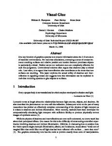
Processor Interface The processor interface (Figure 6) can be divided into three subsections, one which divides apacket into flits and transmits them, second which assembles the flits into a packet and a thud which initializes the routing table. There are two buffers for storing packets in the processor interface block. One of these is meant for incoming packets and the other is intended for outgoing packets. Depending on the input control signals, the controller 1 decides the buffer to which data is to be written. and from where data should be read. Data is written into (or read from) a packet buffer one word at a time. To transmit a packet, the words will be divided into pairs of bits and written into the flit buffer. The controller 2 will attach the flit type to the information bits and will ensure that only one flit is written at a time. This flit-buffer is treated in the same way as other buffers in the receiver modules by the transmitters.
1038
Authorized licensed use limited to: IEEE Xplore. Downloaded on October 29, 2008 at 11:57 from IEEE Xplore. Restrictions apply.
graph topology has been used, the overall design is not restricted to any particular topology. It is provided with a standard interface so that it can be used along with any of the commercial micropmessors available.
I
I
The behavioral description of the muter chip was carried out using Vedog HDL, and a behavioral simulation of the muter was described. The structural description of muter chip was carried out using the Logic-III HDL, and compiled using the silicon compiler OASIS. Since fault-tolerance is essential in a massively parallel computer, an attempt to include some elements of hardware faulttolerance in the design has been made. The attempt was to handle link failure through time out methods. For this purpose, the concept of a test-flit is introduced. A test-flit is sent through all the links periodically. If no acknowledgements are received for the test-flit, then the router chip concludes that the corresponding link has failed. All the flits that are. intended for the failed channel are dropped, hence making sure that no other virtual channels are blocked.
U
Data
Another improvement that can be incorporated to this is to replace the RAM-based look-up table by a hardware adaptive router. This may make the muter dedicated to a particular topology, but will certainly improve the performance.
Tad Ill
Figure 6 : Processor Interface In order to assemble flits into a packet, controller 3 operates in the same way as the transmitter module, except that it does not support virtual channels and no handshake is required. It will remove the flit type specification and combine the bit pairs into words and store in the packet buffer. It will ensure that once a complete packet has been assembled, the next packet will be handled only after the previous one has been read by the host-processor. The routing table initializer will divert first 256 bytes to the muting table, that are written by the host-processor after resetting the chip.
References
3.4 OASIS Implementation OASIS (Open Architecture Silicon Implementation Software)[l2] is a silicon compiler, using which one can give the structural description of a VLSI system and carry out logic simulation, obtain the layout, generate test vectors and perform fault simulation. For this purpose, the circuit description should be given in the Logic-III Hardware Description Language. The flit buffers, packet buffers and the routing table were made using D-flipflops. In buffer the D-flipflops are connected in such a way that they form a shift register of required size. In the routing table, registers are formed using D-flipflops and these register outputs are multiplexed to give the final output. The important part in the design of a subsystem is the design of controller associated with the subsystem. The details of the logic-level implementation of the router chip can be found in [13].
4 Conclusions and Future Work The design of a network router chip, which gives high throughput by implementing wormhole routing using virtual channels has been described. The wormhole routing technique gives minimum message transmission time, and the use of virtual channels ensures maximum utilization of the physical resources such as communication links. The router has been designed as a general purpose one, and is capable of implementing any static routing algorithm by providing a programmable look-up table. By using separate receivers and transmitters for each physical channel, this chip will be able to give very high throughput. Even though for testing the design, the star-
A S Tanenbaum, Computer Networks. 2nd Ed., Englewwd Cliffs, NJ; Prentice Hall Inc. 1992. L M Ni and P K McKinley, A Survey of Wormhole Routing Techniques in Direct Networks, IEEE Comp.. Feb 1993,pp 62-76. W J Dally, Virtual-ChannelFlow Control, IEEE Trans. Par. and Dist. Sys., March 1992,pp 194-205. W J Dally and C L Seitz, Deadlock-Free Message Routing in Multipmcessor Interconnection Networks, IEEE Trans. Comp.. May 1987. pp 547-553. W J Dally et al., The Message-Driven Processor, LEEE MICRO. April 1992.pp 23-39. P R Miller, C R Jesshope and J T Yantchev. The Mad-Postman Network Chip, Proc.Transputing 1991 Vol 2 10s Ltd. pp 5517536. S B Akers. B Krishnamurthy and D Harel. The Star Graph An Attractive Alternative to the nCube. In Proc. of the Int. Conf. on Parallel Processing 1987,pp 393-400. C P Ravikumar and AM Goel, Deadlock-Free Routing Algorithms for Star Graphs, Manuscript, Dept. of Elec. Engg. IIT, New Delhi, India, 1993. A Kuchlous. VLSI Implementation of a Fault-tolerant Routing Algorithm for Star Graphs. B-Tech thesis, Dept. of Elec. Engg.. Indian Institute of Technology, New Delhi, 1993. P Easwar, Adaptive Deadlock-free Routing Algorithms for Star Graphs. M-Tech thesis, Dept. of Math., UT, New Delhi, India, 1993. E Stemheim. R Singh and Y Trivedi, Hardware Modeling with Verilog HDL, Automata Publishing Company, CA, 1990. open Architecture Silicon Implementation Software - User's Manual, Microelectronics Corporations of North Carolina, USA, 1990.
A S Prakash. VLSI Implementation of a Wormhole Router using Virtual Channels. M.Tech Thesis, Dept. of Elec. Engg.. Indian Institute of Technology, New Delhi, 1993.
1039
Authorized licensed use limited to: IEEE Xplore. Downloaded on October 29, 2008 at 11:57 from IEEE Xplore. Restrictions apply.