water reflections. We introduce a descriptor that is not only invariant to scales, rotations and affine transfor- mations, but also tolerant to the flip transformation ...
2010 International Conference on Pattern Recognition
Water Reflection Detection Using A Flip Invariant Shape Detector Hua Zhang , Xiaojie Guo , Xiaochun Cao School of Computer Science and Technology Tianjin University, Tianjin 300072, China {huazhang,xguo,xcao}@tju.edu.cn
Abstract Water reflection detection is a tough task in computer vision, since the reflection is distorted by ripples irregularly. This paper proposes an effective method to detect water reflections. We introduce a descriptor that is not only invariant to scales, rotations and affine transformations, but also tolerant to the flip transformation and even non-rigid distortions, such as ripple effects. We analyze the structure of our descriptor and show how it outperforms the existing mirror feature descriptors in the context of water reflection. The experimental results demonstrate that our method is able to detect the water reflections.
(a)
(c)
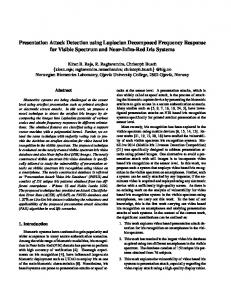
Figure 1. Comparison of matching between our method and MIFT in the water reflection situation (The same color circles represent the corresponding points). (a) An image with water reflection. (b) Matching result using MIFT [4]. (c) Matching result using our method.
1. Introduction
To handle the ripple effects and other complex geometric distortions in the context of water reflection, a novel FLIP INVARIANT SHAPE (FIS) descriptor is proposed in this paper. We first extract the maximally stable boundaries using a method proposed by Riemenschneider et al. [15] which efficiently suppresses background clutters. We next sample a fixed number of points from the stable boundary. Then, a log-polar representation is used to compute the distribution of samples in the image. As the log-polar coordinate system has been divided into 60 bins, our descriptor votes the number of sample points in each bin to obtain the bin with the maximum number (MNB) of sample points and the one with the secondary maximum (SMNB). The rotation direction is indicated by the direction from MNB to SMNB. Moreover, χ2 distance is utilized to compute the similarity of the sample points. Kuhn-Munkres algorithm [12] is adopted mainly due to its advantage of using the weighted edges to obtain the optimal matching. Thin plate spline (TPS) model is used to further improve the matching result. The detection result using our method is shown in Fig. 1 (c). The contributions of this paper include: (1) To the best of our knowledge, this work is the first attempt to attack the water reflection detection problem from unsegmented natural im-
Reflection is ubiquitous in the natural world. Detection of symmetry in the real world has become one of the most intensively studied problems in computer vision and pattern recognition [14]. And reflection detection has been used in many different fields, such as face analysis [11], vehicle detection [5], and medical image analysis [10]. There exists a large number of reflection symmetry detection algorithms ranging from Euclidean reflection symmetry to distorted reflection symmetry detections. Loy and Eklundh [9] proposed a method to detect symmetry and symmetric constellations based on mirror feature descriptor, which is achieved by using SIFT [8] twice to find features. Lee and Liu [7] extended [9] to curved glide-reflection symmetry axis detection. They also adopted SIFT to find feature points. By comparing Euclidean distances between features, a list of similar pairs are obtained. The symmetry axis is then acquired by the matched feature pairs. Guo et al. [4] proposed a descriptor named MIFT that is flip invariant and thus able to detect mirror reflections. However, all these methods are based on SIFT, which use the gradient information. Hence they are sensitive to noises and distortions. As shown in Fig. 1 (b), MIFT fails to match the crane and its reflection. 1051-4651/10 $26.00 © 2010 IEEE DOI 10.1109/ICPR.2010.160
(b)
637 633
(c) (b) (a)
(a)
(b)
(c)
(d)
(d)
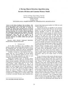
Figure 2. Comparison of boundary detection between our method and Canny. (a) An image with water reflection. (b) Edges detected by Canny. (c) Edges detected by our method (different colors represent different label values). (d) Final detected edges after sampling by our method.
(e)
(g)
(f)
Figure 3. Illustration of the descriptor organizations of our method in the situations with flips.The thick red arrows denote the dominant orientation, and the light curved blue arrows are the encoding directions. (a) The original image of a letter ”G”. The boundary sample points are marked in red dots. (b) The horizontally reflected image of (a). (c,d) Shape context descriptor for (a) and (b). (e,f) The dominant direction and encoding direction for our descriptor are automatically computed. (g) Our descriptor is invariant to water reflection and therefore the same for (e) and (f).
ages, (2) The proposed descriptor is flip invariant which avoids the extra computation of a mirror descriptor, and (3) The leveraged boundary extraction and TPS model updating algorithms effectively handle the ripple effects and the background clutters which often appear in the nature images.
2 Method
sampling method to select N samples based on the locations and the selected points are marked as red dots in Fig. 2 (d) and 3. For each sample, we compute the distribution of the remaining N − 1 points, in the logpolar coordinate system as shown in Fig. 3. And we use 5 bins for log r and 12 bins for θ. We set the value of radius r ( 81 R, 12 R ,R, 32 R , 2R), where R is the mean range of the boundary, as shown in Fig . 3 (a). A 60−dimensional (5 × 12) vector representing the distribution of all the other sample points is used as the descriptor of a boundary pixels. There are two important factors for coding the 60 components, i.e. the dominant orientation and the rotation direction. A naive choice is to adopt the strategy used in [1], where the principal direction is determined by the gradient direction of the current sample point, and the rotation direction of coordinate is fixed (clockwise or counterclockwise). Although this encoding strategy is invariant to rotation and scale, and even tolerant to affine transformation, it hardly works in the situation of mirror reflection as shown in Fig. 3 (c) and (d). We introduce an adaptive encoding technique that is able to keep the advantage of traditional encoding strategy and adjust to horizontally reflected situation. As the log-polar coordinate can be seen as 60 bins, we collect and organize the numbers of sample points in 60 bins to form a 5 × 12 array. We find the maximum value (the blue region) and the second maximum (the green region) in the array. Then the rotation direction is set from MNB to SMNB. We always enforce the first column to contain the max-
2.1 Stable boundary detection Our method is based on the contours of objects within images. Therefore, we need to extract the stable boundaries for the objects. Canny edge detector can obtain boundaries of the objects and their reflections, but the drawback of Canny edge detector is that edges from the background clutters are also presented, as shown in Fig. 2 (b). To overcome this drawback, we instead use the boundary algorithm proposed by Riemenschneider et al. [15] to better achieve our goal. Firstly, we use the component tree [13] data structure to store the labeled extremal region boundaries in the images. The stability of a boundary of a region is based on the similarity of the region boundaries over several levels, which is computed using the chamfer matching algorithm. After that we obtain the stable edgelets with a unique ID for each of them as shown in Fig. 2 (c) (different boundary components are marked with different colors). We then link these edgelets which is greater than a threshold to form a complete boundary. The detection result using our method is shown in Fig. 2 (d).
2.2 The flip invariant descriptor We propose a new descriptor that has the characteristic of flip invariance. We use the log-polar coordinate system since it is proved to be tolerant to scales, translations, rotations, and noises [16, 1]. After acquiring the stable boundary, we sample along the boundaries to reduce computation complexity. We use a randomly 634 638
2.4
(a)
(b)
(c)
After the initial correspondences between sampled points from the two objects are obtained, we consider a plane transformation T : IR2 → IR’2 that is used to map arbitrary points from the object to its water reflection. And IR2 represents the original image plane, while IR’2 denotes a plane which is used to align the object and its water reflection. In our work, we use the thin plate spline (TPS) model [2, 3], which has been widely used for non-rigid transformation models in image alignment and shape matching. In 2D case, given a set of K corresponding points, the TPS warp involves 2(K + 3) parameters that include 6 global affine motion parameters and 2K coefficients for correspondences of the control points. The TPS model has a parameter λ which is used to control how non-rigid transformation is allowed for the deformation. When λ → ∞, the TPS is equal to an affine transformation. The 2D transformation can be separated into two TPS function to model a coordinate transform:
(d)
Figure 4. Matching results use Hungarian method and KM algorithm.(a) An image (b) Hungarian method (c) KM algorithm (d) Matching after using TPS.
imum value bin. So the dominant is changed from A (the original gradient direction) to B (the current dominant direction), as shown in Fig. 3 (e). This method is adaptive to almost all of the special situations in setting directions. The situations as shown in Fig. 3 (e) and (f) obtain the same array based on our method, as shown in Fig. 3 (g).
2.3 Initial matching
T (x, y) = (fx (x, y), fy (x, y)),
We have a K dimensional vector [Pi (1), ...Pi (k)] for each sampled edge pixel Pi . The cost Dij of two distinct points Pi and Pj (i �= j) is computed using the χ2 distance as :
(2)
where the fx and fy is TPS function. We solve this equation to find the bending energy which presents how much transformation is needed to be aligned the points. The regularization TPS is used to relax the exact interpolation requirement and this is accomplished by minimize the following energy
K
1 � [Pi (k) − Pj (k)]2 Dij = , 2 Pi (k) + Pj (k)
Refine matching using thin plate spline
(1)
k=1
where K is fixed to 60 in our implementation. If Pi is sampled from the object and Pj is sampled from its corresponding reflection or close to its corresponding part, Dij shall be small. In the matching process, we want to obtain the one-to-one correspondences among sampling points. So we consider the matching problem as weighted bipartite matching problem. We define Dij as the edge weight from Pi to Pj . We consider the best matching as the sum of all edge weights which are minimized between matched points. There are several approaches to solve this problem. Hungarian method [6] and its variants are used to maximize the number of matches which do not use the edge weights. In this work, we adopt the efficient KM algorithm [12] to realize optimum matching pairs. The comparison is shown in Fig. 4. Another advantage of KM algorithm is its low complexity which is O(n3 ), where n is 400 in our implementation. When the edge weights between matching pairs are greater than τ , we classify that sample point as outlier. To enlarge the difference of the noncorresponding points, we add the Euclidian distance to the edge weights (denoted as FISe ). And in this way, the precision of matching can be further improved by around 10% as shown in the Section 3.
H[f ] =
n �
(νi − f (xi , yi )2 ) + λIf ,
(3)
i=1
where If is the bending energy and λ is the regularization parameter. The purpose of using this TPS model is to reduce errors of the initial estimate of the correspondences, as shown in Fig. 4 (d).
3
Results
We evaluate our proposed water reflection detection algorithm under a diverse set of test images collected from the Internet. Here we use 8 representative images to display our detection results, as shown in Fig. 5. The first three images have cluttered backgrounds, and the last five images are with different intensities of water waves (from light to strong). As shown in Fig. 5, from the second row to the fourth, we show the detection results using MIFT, mirror shape context (MSC) and our method, respectively. Our method (FIS) behaves best to detect the water reflections of the objects, while MIFT and mirror shape context fail to detect the water reflections when the intensities of water waves are nontrivial 635 639
(last four columns in Fig. 5). Quantitatively, the performance comparison among MIFT, mirror shape context, and our method is displayed in Table 1. The applications of our algorithm range from finding the symmetry axis in the image as shown in Fig. 5 and Fig. 6 to detect the objects in other mirror reflection cases, while MIFT fails (Fig. 7 (b), (c)). In the non-flip case, our method works well as shown in Fig. 7 (a). To demonstrate the usability of the proposed method, we also apply it to challenging natural images such as winkle leaves, occluded symmetry objects, nonsymmetric objects as shown in Fig. 6. Our method is shown to be very robust in these tough situations which will hinder the use of SIFT-based mirror reflection detection methods.
(a)
image. (b) and (c) Our method is used to detect the mirror reflections.
References [1] S. Belongie, J. Malik, and J. Puzicha. Matching shapes. In Proc. IEEE ICCV, pages 454–461, 2001. [2] F. L. Bookstein. Principal warps: Thin-plate splines and the decomposition of deformations. IEEE Trans. PAMI, 11(6):567–585, 1989. [3] H. Chui and A. Rangarajan. A new point matching algorithm for non-rigid registration. CVIU, 89(2-3):114– 141, 2003. [4] X. Guo, X. Cao, J. Zhang, and X. Li. Mift: A mirror reflection invariant feature descriptor. In Proc. ACCV, 2009. [5] A. Kuehnle. Symmetry-based recognition of vehicle rears. Pattern Recognition Letters, 12(4):249–258, 1991. [6] H. . W. Kuhn. The hungarian method for the assignment problem. Naval Research Logistic Quarterly, 2(1-2):83– 97, 1955. [7] S. Lee and Y. Liu. Curved glide-reflection symmetry detection. In Proc. IEEE CVPR, 2009. [8] D. G. Lowe. Distinctive image features from scaleinvariant keypoints. IJCV, 60(2):91–110, 2004. [9] G. Loy and J. Eklundh. Detecting symmetry and symmetric constellations of features. In Proc. ECCV, pages 508–521, 2005. [10] M. Mancas, B. Gosselin, and B. Macq. Fast and automatic tumoral area localisation using symmetry. In Proc. IEEE ICASSP, pages 725–728, 2005. [11] S. Mitra and Y. Liu. Local facial asymmetry for expression classification. In Proc. IEEE CVPR, pages 889– 894, 2004. [12] J. Munkres. Algorithms for the assignment and transportation problems. Journal of the Society for Industrial and Applied Mathematics, 5(1):32–38, 1957. [13] L. Najman and M. Couprie. Building the component tree in quasi-linear time. IEEE Transactions on Image Processing, 15(11):3531–3539, 2006. [14] M. Park, S. Lee, P. Chen, S. Kashyap, A. A. Butt, and Y. Liu. Performance evaluation of state-of-the-art discrete symmetry detection algorithms. In Proc. IEEE CVPR, 2008. [15] H. Riemenschneider, M. Donoser, and H. Bischof. Finding stable extremal region boundaries. In Proc. AAPR, 2009. [16] E. Shechtman and M. Irani. Matching local selfsimilarities across images and videos. In Proc. IEEE CVPR, pages 1–8, 2007.
matches/ all matches)
Image a b c d e f g h MIFT 1/17 31/36 3/6 27/27 1/29 0/6 3/14 1/1 MSC 11/2619/29 2/23 6/31 2/24 5/15 3/13 0/11 FIS 27/3510/2535/6924/7613/3515/3823/5916/38 FISe 40/5723/3761/9345/8518/3316/3230/6530/52
(b)
(c)
(d)
(e)
(f)
(g)
(c)
Figure 7. (a) Detecting the apple logo in the non-flip
Table 1. Quantitative results for Fig. 5 (correct
(a)
(b)
(h)
Figure 5. Results of detecting objects and their water reflections. Top to bottom: the original images, results using MIFT, result using mirror shape context, results using our method, and the detected symmetry axis using our method.
Figure 6. Application of our method to detect symmetry axis in the challenging natural images.
4 Acknowledgement This work was supported by NSFC (No. 60905019, 50735003), SRF for ROCS, SEM, Open Projects Program of NLPR, Tianjin University 985 research fund, and SKL of PMTI.
636 640