14th PSCC, Sevilla, 24-28 June 2002
Session 17, Paper 2, Page 1
Wide-Area Adaptive Protection Using Distributed Control and High-Speed Communications M. Kim1
M.J. Damborg1
J. Huang2
S.S. Venkata2
1, Department of Electrical Engineering, University of Washington, Seattle, WA
[email protected] 2, Department of Electrical and Computer Engineering, Iowa State University, Ames, IA
[email protected] Abstract – New concepts of wide-area adaptive protection using distributed control and high-speed communications may reduce the likelihood of catastrophic failures in power systems. We suggest a communication and control structure designed to avoid and/or reduce the impact of misoperations of protection devices, for example, from hidden failures. We propose two different operating modes of the system, anticipative and responsive. We also indicate how such a system can respond to emergencies within the time available. Keywords: Adaptive protection, hidden failures, high-speed communications, distributed control
1.
INTRODUCTION
Many historic, catastrophic blackouts are found to be due, in part, to problems with protection devices. These problems include erroneous settings and device failures, in the form of hidden failures or exposed failures. It is widely believed that protection systems are designed to emphasize dependability rather than security. This approach minimizes damage to system components and is appropriate when a system is in a normal operating state. However, if a system is under stress, for example due to outages or excessive loading, additional switching to isolate faults will cause additional stress that may contribute to large failures. Thus, security has been compromised. We explored an approach that, in times of stress or emergencies, could alter the protection system behavior to emphasize security. We have proposed that bulk transmission protection systems be built using the most recent advances in sensors, computation and communications. Specifically, we propose controllers at each substation to coordinate all switching actions at each station and a control center to provide overall coordination, described in [1] as Substation Coordinated Control. Similar concepts were suggested in [9]. We suggest that this system could manage the
protection system in two modes: an anticipatory mode in which protection device behavior is adjusted to current operation prior to a fault event, and a responsive mode in which the protection system reacts after a fault to limit the impact of protection failures. This coordination system could be introduced into an existing system to oversee standard protection functions. However, we expect that the concept would be most satisfactory if it is integrated fully into basic protection design. We estimate that, with the latest technology, wide-area protection switching actions can be accomplished within approximately 200 ms after a fault. We have developed six examples of protection scenarios, three for each of these modes, and have illustrated them using simulations of a 179 bus system. The examples concentrate on a congested corridor where a multi-line outage, which may result from protection system failures, is known to pose stability problems. In these simulations we demonstrate how rapid data communication and rapid fault analysis can avoid system instabilities. In some of these examples we pose cases where the system takes preventative measures, i.e. anticipates the need for changing the protection system behavior due to, say, a sense of greater vulnerability. In others, the system responds to a protection system failure and stabilizes a scenario that would otherwise lead to loss of synchronism. We provide information of the time available to accomplish these control actions and illustrate that the time required is within the capability of our proposed system. These examples serve to illustrate the performance required of the communication and control subsystems proposed in our approach. 2.
SCC SYSTEM AND OPERATION MODES
The concept of the proposed Substation Coordinated Control (SCC) is illustrated in Fig.1.
14th PSCC, Sevilla, 24-28 June 2002
Session 17, Paper 2, Page 2
Here each line-end is equipped with sensors (S), a line controller (LC) and breakers (B). The line controller is the successor to the modern computer relay. In addition to a local control for each breaker, there is a Substation Coordination Controller (SCC) that receives signals from each sensor at the substation and can control each breaker at the substation. This extra level of logic allows for breaker action based on the state of all lines and bus bars at the substation. While each end of each transmission line must be protected by the autonomous operation of a relay/breaker system, the SCC can provide a coordinated response of all breakers at a substation. Through monitoring, the SCC system will provide alerts in the event of breaker/relay failures, including hidden failures when possible, and will assure proper settings for coordination. The system will also be given an active role to change settings upon command and to coordinate all breakers at the substation to isolate faults based on local information. An example would be to deenergize a minimal portion of a substation in the event of a bus fault that may affect multiple lines.
S B LC
Concepts in Wide-Area Adaptive Protection
In [1] we review the literature of adaptive protection since 1988 and point out its progression from exploration of basic concepts to experiments with specific wide-area applications. We suggest that adaptive protection should progress naturally into two forms: Anticipative and Responsive. In Anticipative Adaptive Protection the protection system’s characteristics are altered in times of system stress. These changes are made before any fault but with the intent that, should such an event occur, the impact of any misoperation of protection devices would be less than with the original characteristics.
S
B LC
B
B S
3.
B LC
S
for truly wide-area emergency management. This system can take advantage of enhanced computation (at relays, in substations and centrally) and modern communications to respond not only to faults but also to threats such as unusual loading or weather. Through a network of substation controllers the protection/control system is organized over a wide area.
S
LC
LC
B S
LC
SCC
SCC
Substation 1
Substation 2 Control Signal Measurement
Central Control
Figure 1:
Communication Link
A coordinated wide-area protection and control
This SCC system will be a major element in a wide area control system that involves protection devices. It must communicate with immediate neighbors for rapid tripping of far-end line faults and for primary-backup coordination. But it must also communicate with the central control system
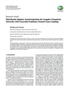
In [2] we explored anticipative adaptive protection in the context of the 179-bus test system shown in Fig.2. This figure suggests a highly equivalenced portion of the Western U.S. system. Under heavy load conditions, this model exhibits major instabilities for faults in the north-south corridor
14th PSCC, Sevilla, 24-28 June 2002
inside the oval in Fig.2 if these faults are not properly managed due to protection system failure. We show how different types of anticipatory action can reduce the impact of protection system failure. Indeed, a scenario that would lead to a major separation of the model can, instead, result in only local disruption consistent with the intent of the protection system. We explored how anticipatory action, during times of perceived vulnerability such as heavy loading or component outage, could alter the protection system behavior to adopt a more “defensive” posture. Examples of such anticipatory action include adjusting relay settings to avoid false trips on temporary overloads as well as altering back up relaying to avoid the possibility of some forms of hidden failures.
Session 17, Paper 2, Page 3
otherwise result in major disruptions. Our focus is to identify how much time is available for action. Hence, we first estimate the time required for wide-area control before proceeding to examples of such action. 4.
The concept of adaptive protection with our proposed structure in [1] and [2] depends on the speed with which the control center can identify and analyze an emergency as well as the speed with which remedial control action can be effected. The total process involves the 6 activities shown in Table 1 with our current time estimates for each. Activity: Sensor Processing Time Transmission time of information Processing incoming message queue Computing time for decision Transmission of control signal Operating time of local device Total
35 33 32 31 30
74
80 79
65 75
78 72 76 vv 77
82 86
83
112
81 8485 162 156157161
114 155 44 115
167
5 11 165 159 158
Ref. [3] [4]1
10 ms
[4]
100 ms
[5]2
10 ms
[4]
50 ms
[6]
185 ms
Table 1: Estimated times for adaptive protection actions.
166 163 1213
7
108 109
119 138139 107 37 110 104 147 64 103 63 143 148 154 102 142146 56 48 153 151 145 136144 4749 140 152 19 150 141 149 57 4342 50 16 15
Time 5 ms 10 ms
6
45160
118
ESTIMATE OF COMMUNICATION AND CONTROL TIMES
18 817 9
14 3
4
Figure 2: A 179-bus test system
The second approach is Responsive Adaptive Protection in which the protection system reacts to an emergency by taking additional switching actions to restrict the impact of a protection misoperation. For example, if a fault occurs and a hidden failure results in unnecessary line outages, major system instability could occur. However, a large outage may be avoided if corrective action can be taken quickly enough. We present three examples of this approach in this paper. Specifically we explore the time available to take corrective action after fault events that would
Our estimate of communication time is based on the assumption that utilities will have a complete fiber optic network available with dedicated channels provided as necessary for high priority communication and control signals. Many utilities are already installing such networks, both for operations and to support new business opportunities providing communication services to their service area.
1
For short messages, the communication time depends almost entirely on the propagation speed along fiber cables (124,138 miles/sec.) [4]. We based our estimate on a distance of 1000 miles plus some delay time for intermediate nodes (0.3 ms per node). Whether there is a node delay depends on the protocols used.
2
The computation time for making control decisions is very indefinite. Our estimate is consistent with that used by the EDF defense plan [5].
14th PSCC, Sevilla, 24-28 June 2002
As seen in the table, we conclude that 200 ms is adequate to accomplish the communication and control actions after fault initiation. 5. 5.1.
EXAMPLES OF RESPONSIVE ADAPTIVE PROTECTION A 179-Bus Test System
The 179-bus test system of Fig.1 is displayed on a background suggesting the Western U.S. and Canada. While the names of actual substations are used, the reader is cautioned that the system operation discussed here does not necessarily represent the actual system behavior. We offer these examples as transients typical of large system dynamics. The simulations have been performed using ETMSP from the PSAPC 5.0 package supplied by EPRI.
Session 17, Paper 2, Page 4
about 50 ms with breakers A and B. The cases we consider involve a hidden failure in the transfer trip system so that breaker B at Malin, 83, fails to clear that end of the line. With this failure of B, the system will resort to a backup-relaying scheme. We hypothesize that all lines at Malin would trip using zone 2 of distance relays 3 . Allowing for relay time delay and breaker actuation, breakers C, D, E, F, and G would all open in 100 ms. This breaker action disrupts the entire AC corridor and, for this heavily loaded base case, the system rapidly looses synchronism. 71
v v
77
D
83
In the responsive mode, the SCC system must respond to an emergency by gathering data, analyzing the problem, and executing control actions quickly enough to avoid a catastrophic failure. In the examples below, we determine how much time is available for executing these communication and control operations. We will see that the 200 ms estimate of Section 4 is sufficiently quick for these cases. All examples concern a permanent three-phase fault between Malin, bus 83, and Summer, bus 86, at a point 10% from Summer as shown in Fig.3. Allowing for breaker actuation time, normal relay action would clear both ends of the line within
86 A
The base case for our study has generation of 61,411 MW and 12,330 MVAR that corresponds to a rather high summer peak. During such times, there is a heavy north to south flow through the area along the left of the system that is carried by both the Pacific dc intertie (not shown) and parallel ac circuits. We have been focusing on this region in developing examples of system problems that would result from relay misoperations. A detail of the test system consisting of the portion of Fig.2 inside the oval is shown in Fig.3 with specific buses and breakers labeled. This segment consists of the high voltage ac system that is parallel to the Pacific dc intertie and is a critical portion of the system. During high loading, faults that result in the loss of multiple circuits here lead to instabilities affecting large segments of the western system.
82
C
B
112
F
E
114
115
118
G
119
Figure 3: A critical portion of the test system with breaker identities shown.
We have developed three examples of how the adaptive protection SCC system can avoid this instability. Each relies on rapidly gathering information on line flows and breaker status from the Malin and all neighboring substations. Then the central controller identifies the problem and takes the remedial action described in the example. In all cases we are concerned with the speed required of the adaptive protection system. That is, we want to know if there is enough time for the protection system to respond to the event before the system becomes unstable and the opportunity to avoid catastrophic failure is lost. Hence, for 3
We assume all six lines are connected to a single bus section. Other bus configurations may behave differently.
14th PSCC, Sevilla, 24-28 June 2002
Session 17, Paper 2, Page 5
each example, we find the maximum time available for the remedial action to be accomplished, a time that depends on system loading. 5.2.
Example 1 – Hidden Failure Recovery
The control center must analyze the information available on the fault to identify the corrective action required. The CT’s on the 6 lines at Malin would be able to detect which line is carrying the major fault current out of the bus. If there were doubt, voltage and current information from the neighboring buses could be compared to identify the faulted line. Additional information would be available from a sequence of events recorder detecting the timing of breaker A relative to the others. Assuming breaker B is operational, the remedial action is to open breaker B and reclose the breakers on the five unfaluted lines. Through simulation we have examined how much time is available for this corrective action to maintain synchronism. The lower set of data points, labeled “Example 1,” of Fig.4 summarizes the results for 8 cases, each at different load levels identified by the change from the base case. The base case represents the already heavily loaded system described before. In fact, a 10% increase in system loads leads to a failure of the power flow to converge. Hence, we explored the cases from a 5% increase down to a 30% decrease from the base case. The time available between the occurrence of the fault and the necessary reclosure action varies between 350 and 830 ms. Load adjustments are applied uniformly at all load buses. 1800
Available Time [ms]
1600
Example 1
1400
Example 2
1200 1000 800 600 400 200 0 -30%
-25%
-20%
-15%
-10%
-5%
0%
Change from Base Load Condition
Figure 4: The time available for remedial action
5%
5.3.
Example 2 – Centralized Backup Relaying
The relaying failure scenario of this example is the same as that of Example 1. The differences are in the response of the protection system. Specifically, all back up relaying is supervised and managed by the Central Controller. As in Example 1, breaker A opens in 50ms, because the primary relay operates autonomously, but breaker B fails to operate due to the hidden failure. Zone 2 backup relaying is blocked or delayed by the Central Controller so the other lines at Malin remain energized. Upon assessing the status of the system, the Central Controller commands breaker B to open without any disruption of the other lines. In making this assessment, the Central Controller depends on information from all relays sensing the fault and appropriate logic. This logic would probably include algorithms that can incorporate data uncertainty and incompleteness such as voting schemes, perhaps with fuzzy techniques [7]. The upper set of data points in Fig.4, labeled Example 2, indicates the time available for this centralized backup relaying action for different system loads. Note that for loads that are 20% less than the base case, the system is stable even if breaker B remains closed. Of course, the fault currents are of concern and breaker B would be opened as quickly as the adaptive protection system could manage. The times displayed in Fig.4 represent the maximum time available. 5.4. Example 3 –The effect of a Temporary Reduction of Power Flow In Example 1, where breakers C through G must be reclosed and breaker B opened, the time available for remedial action is quite short for high load levels. Even though the time available is longer than the 200 ms we estimate to be required, we wanted to explore whether the available time could be extended if we could temporarily reduce the flow through the affected lines. Since this portion of the Western U.S. system is parallel to the Pacific DC intertie, we hypothesized that we could shift some load rapidly to that system, perhaps very temporarily. Indeed, the DC intertie is not used for such purposes and such a shift may be inappropriate for various operational reasons. However, other mechanisms for flow reduction may be possible since, as we shall see, the shift can be very temporary if we are only concerned about maintaining synchronism. For example, it may be possible to divert flow through some other part of
14th PSCC, Sevilla, 24-28 June 2002
Session 17, Paper 2, Page 6
the system or even shed some load for a brief period. For the reader’s information, the Pacific DC intertie (PDCI) connects the Celilo Station, bus 71, with the Sylmar Station in the Los Angles area, a distance of 1361 Km. Fig.3 shows the terminal at bus 71 but the Sylmar Station is outside the area shown. While studying the controls for power flow on the DC line is beyond the scope of our study, we believe that flow can be altered very rapidly using electronic controls. Fig.5 plots the time available when the system is loaded as in the base case and the DC flow is increased by 1000, 2000, or 3000 MW. We see that the available time increases from 360 ms in the base case to 430 ms for a 3000 MW increase in DC flow. In these studies, we assumed that the flow diversion occurred at the same time as the remedial switching action. That is, in the case where the DC flow was increased by 2000 MW, the system could wait a maximum of 410 ms to divert that flow and accomplish the breaker switching. 440
Available Time [ms]
430 420
from 350 to 410 ms providing the DC flow is also increased by 2000 MW at that same time. That is, the DC flow increase gains 60 ms before action is required and the flow diversion need be maintained for only an additional 440 ms or until 850 ms from the time of the fault.
Figure 6: Time available for remedial action after increasing DC flow by 2000 MW
Again, it is not clear that such operation is feasible on the present DC system or any other but it illustrates some of the important interactions of the system components during faults. It is known that the PDCI is capable of transmitting up to 3100 MW in normal operation and 3650 MW for tenminutes [8].
410
5.5.
400 390 380 370 360 350 0
1000
2000
3000
Increase in DC flow [MW]
Figure 5: The time available for remedial action after changing of HVDC flow
We were also interested in how rapidly the DC flow could be restored to its original value and maintain synchronism. Fig.6 illustrates the result for the case of a 2000 MW transfer to the DC line and for loading of the base case as well as 5% changes above and below the base case. The lower data points are a repeat of the result in Example 1 with no load diversion. The middle data points are the time available when there is a 2000 MW diversion and the upper data points identify the minimum time, from the time of the fault, that the DC flow can be returned to its initial value. For example, when the loading is 5% above the base case, the available time for action is increased
Comments on Relay Algorithms
As stated at the outset, our effort has concentrated on understanding how much time is required for wide-area protection data acquisition and control and to compare that time estimate with one of how much time is available for avoiding catastrophic transients. Comparing the data in Table 1 with the times for remedial action in these examples, we see that central protection decisions resulting in dispersed action is feasible in realistic situations. We have not focused on what algorithms might be used for deciding on remedial action. Table 1 allows 100 ms for these decisions, which we believe to be adequate for many types of network analysis and decision algorithms. 6.
CONCLUSION
We believe that adaptive protection based upon the latest technologies can contribute to both preventing and eliminating emergencies involving faults and hidden failures that could otherwise lead to wide-area disturbances. Our concept is quite nonstandard for the industry but we think it is
14th PSCC, Sevilla, 24-28 June 2002
consistent with the directions of technology development now underway. We also believe that controls of this nature will be required to avoid major system disruptions which are still all too common. We remind the reader that we do not suggest that the Western U.S. system will behave exactly as in our examples. Rather, the examples cited here are intended to illustrate how the proposed protection system might respond in realistic situations. It remains to study applications and to evaluate this concept in a specific, operational system. Finally, the reader may be interested in ongoing developments in communications architecture and protocols specifically for the electric utility industry [10]. REFERENCES [1] M.J. Damborg, M. Kim, J. Huang, S.S. Venkata, A.G. Phadke, “Adaptive Protection as Preventive and Emergency Control,” Proceedings, IEEE PES Summer Meeting, Seattle WA, vol. 2, July 2000. pp. 1208-1212. [2] M.J. Damborg, S.S. Venkata, J. Huang, M. Kim, “Examples of Adaptive Transmission System Protection Using Rapid Communication and Control” Proceedings, MEPCON’2001, Egypt, 2001. [3] P. K. Dutta and P. B. Dutta Gupta, "Microprocessor-based UHS relaying for distance protection using advanced generation signal processing," IEEE Trans. on Power Delivery, vol. 7, no. 3, July 1992, pp.11211128. [4] G. Li, J. Yates, R. Doverspike, and W. Dongmei, “Experiments in Fast Restoration using GMPLS in Optical / Electronic Mesh Network,” Optical Fiber Communication Conference and Exhibit, 2001. OFC 2001, 2001 pp. PD34_1 -PD34_3.
Session 17, Paper 2, Page 7
[5] O. Faucon and L. Dousset, “Coordinated defense plan protects against transient instabilities,” IEEE Computer Applications in Power, vol. 10, no. 3, Jul 1997, pp. 22-26. [6] J.L. Blackburn, Protective Relaying: principles and applications 2nd Edition, New York: M. Dekker, 1998. [7] M. Kezunovic, “Intelligent systems in protection engineering,” Power System Technology, 2000. Proceedings, PowerCon 2000, vol. 2, pp. 801-806. [8] F.E. Elliot et al, "FEM-Study on converter transformer failures in the Celilo HVDC converter station," IEEE Power Engineering Society 1999 Winter Meeting, Vol. 2, 1999, pp.1047 -1052. [9] J.C. Tan et al, "Intelligent wide area back-up protection and it's role in enhancing transmission network reliability," Developments in Power System Protection, Seventh International Conference on IEE, 2001, pp. 446 -449. [10] Draft Input for the Utility Communications Architecture Version 2.0, EPRI, available at ftp://ftp.sisconet.com/epri/subdemo/uca2.0/intro.doc.
ACKNOWLEDGEMENT This research is sponsored by the Electric Power Research Institute and the U.S. Department of Defense through the Initiative on Complex Interactive Networks / Systems (WO8333-01).