0 w. + a a. 2 ;. 1. Fig. 1. (a) Diffuse optical channels connecting terminal ... region as signal carrier to interconnect a cluster of terminals ... direct line of sight required between transmitter and receiver, ... resulting time dispersion is analyzed assuming a signal which is ...... dark or fluorescent lighting with a lower infrared.
PROCEEDINGS OF THEIEEE, VOL. 67, NO. 1 1 , NOVEMBER 1979
1474
Wireless In-House Data Communication via Diffuse Infrared Radiation FRITZ R. GFELLER
AND
URS BAPST
Abstmet-A novelwireless broadcast/multi-acwschannel is descn'bed for flexibly interconnect@ a duster of data terminals located within thesameroom.ThetMgniPsionmediumisdiffusivelyscatteredinfrored radiation at 95Oam melength. Transniasion is low-twnedium speed and the range up to 50 m. Theoretical analysis indicates that the time dispersion limits the trmsmission bandwidth of the system to 260 "bit. m/s, but background noise produced by ambient . .daylightreduces the trnnsmission speed bdow 1 "bit/& The trrnsrmsslon propertiesot the diffiw optical channel are analyzed, and experimental digital links for basebaud F"at 125 kbit/s and PSK 64 kbit/s are demonstmted.
w
I. INTRODUCTION
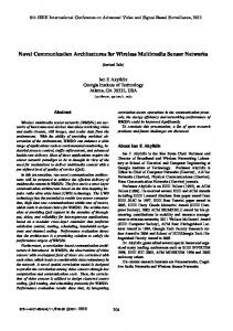
E ARE at present facing an enormous growth of computer-based terminal stations. These terminal stations are interconnected t o form distributed or centralized a computer networks of increasingcomplexityanddensity to 0 a a 1 performavariety of functions.Intheofficeenvironment, w + 2 ; individual word processing, data processing, and information systemsmovetowardsintegratedofficesystems.Onthe shop-floor level, process control,manufacturing,andtesting depend increasingly on a multitude of interconnected terminal stations such as sensors, transducers, microprocessors, or industrial robots. Similarly, in the merchandising environment, cash-register terminals, stock taking, or order placements are becomingincreasinglya part ofcommondata-processing systems. This development has had an impact on the system architecture and a number of pertinent architectures has.been conceived [ 11-[ 3 I with an end to flexibility and adaptation to growth. Fig. 1. (a) Diffuse optical channels connecting terminalclustersinan In the same room or shop floor there is often a multitude of in-house environment. S = satellite, T = terminals. (b) Diffuse optical-channel network. terminals clustered together. There is a need to flexibly place terminals at different positions within the same room t o suit particular working conditions, to reconfigurate existing terminal arecostlyandcausedowntime.Inaddition,theremay also arrangements, or even t o -havemobilehand-heldterminals. be problems with ground loops and noise pickup. Examples are cash-register terminals in supermarkets or data A . Wireless Optical Channel terminals in a production plant where economic production of a particular model requires frequent modifications in number An alternative to cabling is wireless communication. In this and location of the terminals. paper, we propose diffuse optical radiationin the near-infrared The conventional method of interconnecting terminals is by region as signal carrier to interconnect a cluster of terminals wiring. There is often a multitude of different cable types to located in the same room to a common cluster controller [41. suitparticulartransmissionspeeds. While mainspowering is In principle, each terminal interface is equipped with a lightreadily available and prewired with tapping points within easy emittingdiode LEDanda photodiodefor convertingan reach, signal cables may have to be pulled individually. Actual electronic signal t o an optical signal, and vice versa, and the situations are very diverse and difficult t o categorize, but, in corresponding driver and receiver circuits. Similarly, a central general, the cabling problem ranges from lowcost solutionsof optical satellite station serves as an interface t o the common loose cables on the floor to crowded ducts or even raised floors cluster controller which may be local or remotely connected with hgh costs. Once the cables have been installed, changes via a conventional wire link (see Fig. l(a)). Optical radiation fromthesatellite(downlink) is diffuselyscattered from the surrounding walls, ceiling, and other objects in the room, thus Manuscript received February 8, 1979; revised June 22, 1979. filling the entire room with the optical signal carrier. Reception The authors are withthe IBM ZurichResearch Laboratory,Riischis nondirectional, i.e., the photodiodes receive the incoming likon, Switzerland. W
J
0018-9219/79/1100-1474$00.75 0 1979 IEEE
GFELLER AND BAPST: DATA COMMUNICATION DIFFUSE VIA
IR RADIATION
1475
an address and the numberof users is only bounded bychannel radiation from a wide field of view (FOV). Hence, there is no direct line of sight required between transmitter and receiver, capacity. There is no limit to temporarily inactive users beyond and the optical transmission path is very insensitive to inter- that of finite address field size. An in-house system based on ruption. The same transmission method applies for the uplink diffuse optical channels may be expanded or contracted with(terminals to satellite). out major changes and offers great flexibility. A diffuse optical channel could also serve as a subnet in a local area network. A comparison between diffuse optical and radio-frequency transmission reveals the following aspects in favor of the optical link: with radio-frequency transmission FCC regulations apply C. Overview of the Topics Addressed within the range 10 kHz to 300 GHz. There are two classes, In this paper, we present a study on the potentialand limitanamely, licensed transmitters and unprotected restricted radiations of the diffuse optical channel. Our effort has been contion devices. Fortheapplications considered, licenses are centrated mainly onthe physicaltransmission properties, obtainedwith increasing difficultydue to the overcrowded to multipath signal namely, bandwidth limitations due spectrum. dispersion, optical power demandfor satellite andterminal The optical signal carrier considered does not fall under FCC interfaces, as well asrangeand distribution of the diffuse regulations and thereis n o interference with the electromagnetic optical radiation field. spectrum. In contrast to radio-frequency antennae, the In Section 11, we describe an idealized diffuse optical channel. dimensions of LED and photodiodes are small, and the optical It can be visualized as a transmitter and receiver sitting in an radiation is essentially confined to the room where it is gen- optical cavity representinga room. If the cavity walls are erated.Thereisthusnointerferencewith similar systems uniformly illuminatedby thetransmitterthentheoptical operating next door and ahigher degree of data security is signal power incident on the receiver photodiode is constant, affordedthan radio-frequencytransmissioncanoffer. An irrespective of thelocationandorientation of the receiver interesting possibility in connection with diffuse optical within the cavity. This is a most desirable feature which, howtransmission is the operation of wireless hand-held terminals. ever, can only be approximated in practice. We also investigate Progress inlow powerconsumption microprocessors,liquidtheeffect of multipathpropagation within the cavity. The crystal displays, andminiaturekeyboardshas brought a resulting time dispersion is analyzed assuming a signal which is batterydriven personal terminal within the state of the art diffusely reflected from a plane surface(ceiling). A bandwidth[51, [61. Conceivable applications are message transmission, distance product is then derived indicating an upper bound for paging, voice transmission, remotecontrol,stock taking, or the transmission speed for a given room size. classroom teaching. In Section 111, abaseband PCM receiver is discussed both been Since the appearance of the first LED therehas theoretically andexperimentally.Apartfromthe infrared enormous progress in the technology of electrooptical comsignal, the receiver photodiode is also exposed toambient ponentsforoptical communications. Of special importance light. A photon striking the photodiode produces, withagiven to us are high radiant output, high efficiency LED’s, sensitive probability, ahole-electronpair which is manifested as an large-area and lowcapacity pin photodiodes, as well as low- electrical currentintheexternal circuit.Since this is a noise optical receiver circuits. Ontheconsumermarket, statistical process, the generation of the photocurrent due to wireless infrared devices have already madetheir mark in ambient light is associated with noise which degrades the remote controlof TV sets and earphones for audio transmission. transmission quality. Some typical ambient-light levels in office environments have beenmeasuredand optical filters B. System Aspects for blocking part of theambient light are discussed. The optical receiver power required for a prescribed transmission The diffuse optical channel can be visualized as a completely error rate is then calculated with the ambient-light level and connected network (see Fig. l(b)). Optical radiation from the transmission speed asparameters. Finally, an experimental satellite (downlink) reaches every terminal within the room, PCM receiver operating at 125 kbit/s is described. Measurethus forming a broadcast channel. Since this channel is used ments of the error performance showed good agreement with only for the satellite, no collisions of data packets can occur. The terminals select only packets addressed to themselves and theory. However, with baseband receivers, transmission discard the rest. Radiationfromtheterminals reaches the integrity may be impaired in the presence of fluorescent lamps satellite as well as the other terminals. (However, there may emitting light with frequency components falling within the receiver passband. be “hidden” terminals not in contact with one another.) The Section IV addresses the infrared field distribution in a comuplink is thus a multi-access channel.Here, the problem of time sharing among all users arises. Access may either be plex environment. A brief survey of the infrared reflective random or by polling. The polling process may be based on an properties of office interiors is given. A computer model is SDLC-type protocol where the cluster controller serves as a then described simulating the distributionof the diffuse infrared LED configuraprimary station. A performance analysis of various random field for a given room geometry and transmitter access methods suchas ALOHA or carrier-sense multiple-access tion. With the aid of this simulation model, suitable LED CSMA has been given by Kleinrock et a2. [ 71. Data transmis- configurations can be found that provideasufficiently unisionmay be either baseband PCM orbymodulated carrier form illumination of a given interior. A case study of three methods such as FSK or PSK. The carrier method offers the different room geometries and satellite LED configuration is possibility of having several separateoptical channels. The then presented. Finally, using the above three cases as an exdiffuse optical channel supports a large population of active ample, the opticalpower neededfor a 64 -kbit/slink is estimated andinactive users. In wire communications,the maximum for both thesatellite interface and the terminal interfaces. number of users is often bounded by some hardware limitaSection V deals with an experimental 64-kbit/s PSK transtions. In wireless communications each user is represented by mitter-receiver interface using a 256-kHz carrier. The use of a
1476
PROCEEDINGS IEEE, OF THE
VOL. 67, NO. 11, NOVEMBER 1979
carrier allows operation of several separate channels. Furthermore, thereceiver passband is shifted away from the baseband, thus allowing effectiveelectricalfiltering of ambient-light fluctuations. 1
,q -
II. IDEALIZEDDIFFUSEOPTICALCHANNEL
/
REFLECTING SURFACE
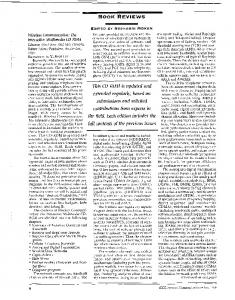
A. Optical Power Received from Diffusely Reflecting Surface The key features of the diffuse optical channel are readily derived from a simple idealized model. An optical source illuminates an arbitrarily shaped surface A such that the radiant emittance w (power emitted per surface area into hemisphere) is constant over theentire area A (see Fig. 2). We further assume that the surface is an idealLambertianreflector.A RECEIVER photodiodewith photosensitive area AR and field of view FOV is then subject to the diffusely scattered radiation from Fig. 2. Optical power received from diffusely reflecting surface. surface A . The system optical source (satellite), a cavity with diffusely reflecting surface A (representing the physical bounds of the room), and the photodetector (terminal) thus form a where p = 1 and FOV = 90'. This wouldrequire thatthe diffuse optical channel. Theoptical power incidentonthe photodetectors be in close contact with the radiating surface photosensitive area AR from the surface element dA is given A = A F . Note that P,, is also the power contained in direct by line4-sight radiation from a distant source falling normally upon the area AF. Theproblem inareal environment will therefore be to to the reflectingsurfaces as distributethesourceradiation homogeneously as possible, bearing in mind their size, where geometry,and reflective properties, in orderto achieve an 1 approximately constant received signal power level over the dS1 =- AR COS 6, if AR