Proceedings of the 2011 6th IEEE International Conference on Nano/Micro Engineered and Molecular Systems February 20-23, 2011, Kaohsiung, Taiwan
Wireless Networks Wind Sensor Based on Micro Wind Velocity Chip and Electronic Compass Lidong Du, Zhan Zhao IEEE-Member and Zhen Fang
Jing Xu, Li Xiao, Daoqu Geng and Junjuan Zhao
State Key Laboratory of Transducer Technology Institutes of Electronics, CAS Beijng, China
[email protected],
[email protected]
Graduate university of Chinese Academy of Sciences Beijing, China
velocity chip is introduced; the experimental results is exhibited.
Abstract—In this paper a kind of wireless networks wind sensor, based on micro wind velocity chip and electronic compass, is introduced. The micro wind velocity chip, which is fabricated with MEMS technology, is designed based on drag force and thermal principle. When the output of micro wind velocity chip is max value, the wind sensor obtains wind velocity and direction by measuring the value of micro wind velocity chip and electronic compass. Moreover, the package of wireless networks wind sensor is designed. By adopting rotation structure, the wind sensor package is especially suitable to use in weather monitoring WSN.
II. SECTIONS OF SENSOR The wireless networks wind sensor is shown in Fig.1. It includes three sections: micro wind velocity chip, electronic compass and main control.
Keywords- Wireless Networks Wind sensor, Micro Wind Velocity Chip, Electronic Compass.
I.
INTRODUCTION
Recently, natural disasters frequently happen in our country. One of the reasons is short of weather information. Although there are many weather monitoring stations, it need many more weather station established in many harsh environment such as: high mountain and forest etc. Currently, the sensors of weather station are not suitable to establish in harsh environment [1] because big volume and high cost. As an important parameter, wind information is especially lack in harsh environment. Fortunately, The MEMS technology and the wireless sensor network have advanced the development of wind sensor. The MEMS based wind velocity chip has the advantages such as: small volume, low cost and high portability. And the technology of wireless networks has made the wind sensor can easily use in harsh environment and automatically collect and send data.
Fig.1 Photo of wireless networks wind sensor
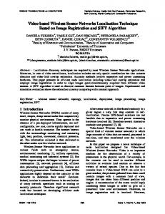
A. Micro wind velocity chip The micro wind velocity chip, based on drag force and thermal principle, is embedded in a polytetrafluoroethylene rod with a hole and has a dimension 9mm×8mm×0.35mm. Fig. 2 shows two types velocity measurement chip: type A and type B. Each of them is divided into two parts: mechanical part and thermal part.
Usually, on one hand, most of weather monitoring system based on wireless sensors networks (WSN) focused on developing middleware, data aggregation, data management, data fusion and networking techniques for large scale networks [2, 3]. On the other hand, most wind sensor research concentrated on the structure and sensitivity material. However, few studies fix attention on wireless networks sensor. Recently, our group has developed MEMS based wind velocity chip [4] and designed wireless networks platform. In this paper, a novel wireless networks wind sensor is designed in which MEMS based wind velocity chip and electronic compass is integrated. In the paper, the section of the wireless networks wind sensor (WNWS) is illustrated; the simply fabrication process of wind
This paper is based on research funded through State 863 High Technology R&D Key Project of China under grant number 2009AA045300, and National Basic Research Program of China (973 Program) under project No. 2011CB302100
978-1-61284-777-1/11/$26.00 ©2011 IEEE
900
Fig.2 The simplified model of the micro wind velocity chip (a) type A: one plate two cantilevers (b) type B: one plate one cantilever.
The mechanical part of type A, which is shown in Fig.2 (a), includes one plate and two cantilevers on which have four platinum resistors. The mechanical part of type B, which is shown in Fig.2 (b), includes one plate and one cantilever on which have four platinum resistors. When wind blows to the sensor it will transform the energy of wind into mechanical energy and measure mechanical energy by the resistors on cantilevers. The four resistors of type A are all distributed on the two cantilevers each of which has two perpendicular resistors. One is used to measure tensile strain and another is used to measure compress strain. Concerning type B the four resistors, two of which are used to measure tensile strain and another two of which are used to measure compress strain, are distributed on one cantilever. Such distribution, in which the resistors are almost in the same environment, will eliminate environment temperature effects to the stabilization and accuracy of the sensor. The thermal part of two types designed sensors consists of a double-side clamped beam on which have two platinum resistors. When the wind blows to hot wire the resistance of them will decrease or increase with the wind velocity. In the thermal part two resistors is on the beam and another two is on the substrate of the sensor. This structure forms a simple hot wire anemometer. The wind velocity is both measured by Wheatstone bridge in mechanical part and thermal part. The micro wind velocity chip is fabricated with MEMS technology. The processes mainly include thermal oxidation and low pressure chemical vapor deposit (LPCVD) to form the mask layer of wet etching; lift-off step to forming the resistors of mechanical and thermal part; also consist of SF6 plasma etching, diluted HF acid etching and KOH etching steps in both front and back side to forming the structure of mechanical and thermal part. After the wafer-level chip is diced, the chip is firstly packaged with PCB. Then the packaged wind chip is encapsulated in a polytetrafluoroethylene rod with a hole. By far, the wind velocity sensitive part of wireless networks wind sensor is completed and shown in Fig. 3.
networks wind sensor a two-axis magnetic electronic compass, HMC1052 of Honeywell the diagram of which is shown in Fig. 4, is used in convenience. The electronic compass is mainly used to get the information of wind direction cooperated with wind velocity chip.
Fig.4 Diagram of electronic compass.
C. Main control The main control section of WSWN is depicted in Fig.5, which includes microcontroller (MCU), power and communication parts. The MCU is C8051F410 chip which collects and processes data and maintains communication with RF module. Power is supplied by a 3.7V 1900mAh lithium polymer battery pack. The CC2520 is used as the communication part, which is TI's second generation IEEE 802.15.4 RF transceiver for the 2.4 GHz band. It is more reliability and stabilization and less power consumption, can reduce the load on the WNWS, and is more appropriate used in WNWS. The CC2520 radio is wired to a hardware interrupt that can wake up the processor upon the arrival of an incoming packet.
Fig.5 Main control part of WNWS Fig.3 The wind velocity sensitive part of wireless networks wind sensor
B. Electronic compass Two-axis magnetic compass measures the horizontal earth magnetic field using two perpendicular magnetic sensor, called the X and Y-axis sensor, in the horizontal plane. Each of them measures the magnetic field by its sensitive axis. The azimuth of the compass is provided by the function tangent(Y/X). A two-axis compass can accurately measure the earth magnetic as long as the sensors remain horizontal, or perpendicular to the gravitational vector. If the compass is inclined, the inclined angle and all three dimension magnetic field (X, Y, Z) must be used in order to calculate azimuth. In our designed wireless
III.
RSULTS
In the designed wireless networks wind sensor, the characteristic of micro wind velocity chip is illustrated in Fig.6 when wind is perpendicular with the chip, and displayed in Fig.7 when the wind velocity is fixed while the angle of wind is changed. It is obvious that, when wind direction is 90 and 270 degree, that is, is perpendicular with the micro wind velocity chip, the output signal of it is the maximum.
901
When the output of wind velocity chip is max value, the angle of earth is corresponded to the wind direction. However, it is difficult in practical WSN circumstances. In prectice, the designed wireless networks wind sensor need to find the orintation of maximum output. In this paper, we design a step motor system. The maximum output of wind velocity ship can be obtained by rotating the sensor a cycle under the control of stepping motor, illustrated in Fig.9, according to the practical requirement.
Fig.6 mechanical part and thermal part change as wind velocity
Fig.9 mechanical part and thermal part change as wind velocity
The rotation system includes a stepper motor and its corresponding driver circuit controlled by another MCU. The package of it is designed using PTFE material, which dimension is 63mm X 92mm. The stepper motor is mounted on top of structure inside of the package. Rotation ratio is changed according to requirement of wind measurement. The rotation system is connected with the wireless networks wind sensor by a interface. Thus the wind sensor can rotate with the rotation system.
(a)
IV.
(b) Fig.7 (a) mechanical part; (b) thermal part rotate charactoristic of micro wind velocity chip
In this paper, the wind velocity and direction is designed to be deduced based on micro wind velocity chip and electronic compass. The characteristic of electronic compass is shown in Fig.8 at fixed angle.
CONCLUSION
Wireless sensor networks enable harsh environment monitoring. Especially, when the MEMS-based sensor is used in wireless networks, the harsh environment monitoring becomes more feasible. In this paper, a wireless networks wind sensor has been designed and fabricated that is portable in small size. Wind velocity and direction are deduced by the maximum output of wind velocity chip and the direction of electronic compass. By introduced a rotation system in the wireless networks wind sensor, the sensor is more feasible using practical circumstance. Compared with conventional wind sensor, the designed wireless networks wind sensor is suitable to monitor the wind in harsh environment. To our knowledge, it is the first wireless networks wind sensor integrated MEMS-based wind velocity chip and rotation structure supplemented with electronic compass. In future work, we need to enhance the performance of the designed wind sensor and improve the efficiency and accuracy of harsh environment wind monitoring.
ACKNOWLEDGMENT Fig.8 Characteristic of electronic compass at fiexd angle
902
[2]
Authors would like thank all people concerned in experiment, and like thank Professor Xiaolei Wang for her help in the sensor design and test, and like thank the MEMS technology engineer for their help in fabrication of sensor.
[3]
REFERENCES [4] [1]
G. Barrenetxea, F. Ingelrest, G. Schaefer, M. Vetterli, O. Couach, and M. Parlange, “Sensorscope: Out-of-the-box environmental monitoring”, In Proceedings of the IPSN 2008, St. Louis, USA, pp.332–343.
903
A. Mainwaring, J. Polastre, R. Szewczyk, D. Culler, and J. Anderson, “Wireless Sensor Networks for Habitat Monitoring”, In Proceedings of the WSNA 2002, Atlanta, USA. G. Tolle, J. Polastre, R. Szewczyk, D. Culler, N. Turner, K. Tu, S. Burgess,T. Dawson, P. Buonadonna, D. Gay, and W. Hong, “A macroscope in the redwoods”, In Proceedings of the SenSys 2005, San Diego, USA, pp.51–63. Lidong Du, Zhan Zhao, Zhen Fang, Jing Xu, Daoqu Geng, Yonghong Liu, “A micro-wind sensor based on mechanical drag and thermal effects”, Sensors and Actuators A: Physical, 155(1), pp.66-72, (2009).