microcontroller (ATMEGA16) because of its inbuilt ADC port and its .... source software development tools for the Atmel AVR series of RISC microprocessors hosted on the Windows .... Monitoring System Using ZigBee Based Wireless Sensor.
International Journal of Computer Applications (0975 – 8887) Volume 69– No.23, May 2013
Wireless Personal Area Network based Simulation and Design to Control the Speed of Permanent Magnet DC Motor using Zigbee Transceiver Protocol Jeetender Singh Chauhan1, Gyan Prabhakar2, Sunil Semwal3, Atul Kumar Pandey4 1
Research Scholar, Instrumentation & Control Engineering Graphic Era University, Dehradun 2 Head Electronics & Communication Engineering Dep’t Saroj Institute of Technology & Management, Lucknow 3 Asst. Professor, Electrical and Electronics Engineering Dep’t Graphic Era University, Dehradun 4 Asst. Lecturer, Electronics & Communication Engineering Dep’t Saroj Institute of Technology & Management, Lucknow
ABSTRACT DC motor has wide range of applications ranging from industrial applications to household applications. In industrial applications several parameters have to be considered for optimized production i.e. rate of production. DC motor speed and orientation control provides sustainable systems with smoother operation, controlled torque, utilization of one system for different processes etc. This paper provides wireless speed control of DC motor for efficient utilization in industrial applications. The system consists of a transmitter which generates control signals which are wirelessly transmitted to the receiver. The receiver according to the control signals controls the speed of the DC motor provided by Pulse Width Modulation (PWM).The control signals are transmitted using RF wireless module Zigbee. Hence forth the speed of the DC Motor can be controlled wirelessly through a control room which makes the system sustainable.
Keywords:
DC Motor, Wireless speed control, Pulse Width Modulation, Zigbee, sustainable
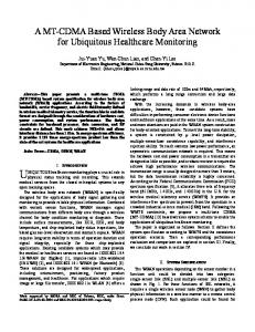
orientation according to the field of interest. The system consists of a Transmitter module which generates control signals which contains information about the speed and orientation of motor depending on the application area. These signals are transmitted to the Receiver wirelessly through wireless RF module Zigbee. The receiver according to the control signals controls the speed of the motor by Pulse Width Modulation (PWM).Pulse Width Modulation (PWM) is the technique of utilizing switching devices to produce the effect of a continuously varying analog signal. This PWM conversion generally has very high electrical efficiency and can be used in controlling either a three-phase synchronous motor or a three-phase induction motor .It is desirable to create three perfectly sinusoidal current waveforms in the motor windings, with relative phase displacements of 120°. The production of sine wave power using a linear amplifier system would have low efficiency, maximum of 64%. Efficiency can be increase up to 95% if instead of the linear circuitry, fast electronic switching devices are used, depending on the properties of the semiconductor power switch. The result is a load current waveform that depends mainly on the modulation of the duty ratio.
1. INTRODUCTION The vast potential in wireless personal area networks is an emerging area of research in recent years. By networking large numbers of tiny motes or nodes, it is possible to obtain data about physical phenomena that was difficult or even sometimes impossible to obtain in conventional ways. The wireless nodes have certain tradeoffs in terms of size, power, cost, code size, and data rate. The hardware design is simple and cheap, but is larger in terms of size when compared with Mica Mote. Zigbee wireless standard was chosen as a communication protocol. The transmission achieved is a real time data transmission with data rate of 250kbps.The applications of DC motor range from household products i.e. vacuum cleaners, hair driers to Industrial applications i.e. reciprocating machines, presses shears. This paper provides a system that can utilized to use DC motor for various applications. We can utilize the DC Motor for various applications by controlling the speed and
Fig 1: Wave form at different duty cycles
6
International Journal of Computer Applications (0975 – 8887) Volume 69– No.23, May 2013
2. HARDWARE DEVELOPMENT Hardware of this wireless system basically constitute of two parts: Transmitting or Slave End node design and receiving or coordinator node design.
(a) Slave End node design-Components of the slave system is given below
(1)Power supply modules-This module is basically designed to achieved 5V, 500mA.This consists of a transformer which is used to step down the AC voltage, IN4007 diodes used to form a bridge rectifier to convert AC to DC, capacitor 1000uF which used as a filter circuit, 7805 regulator to obtain a 5V at the output of the regulator, 330 ohm resistance, LED as indicator.
(4)Zigbee Module(Transmitting module (RF Modem, 9600 bps,TTL logic)-It is a low power and low cost 2.4 GHz transceiver designed for wireless applications. which can facilitate the OEM designers to design their remote control applications in remote control in the quickest way. These modules are based on IC CC2500 by Texas Instrument. The main operating parameters and the 64-byte transmit/receive FIFOs of CC2500 can be controlled with the help of an SPI interface. In a typical system, the CC2500 can be used together with a microcontroller and some passive components.
Fig 2: Diagram of power supply section
(2)AVR Microcontroller-There is a whole wide range of microcontroller available in the market. But this particular project is developed using AVR series of microcontroller (ATMEGA16) because of its inbuilt ADC port and its variable frequency. ATmega16 is a low-power CMOS 8-bit microcontroller based on the AVR RISC architecture. By executing powerful instructions in a single clock cycle, the ATmega16 achieves throughputs approaching 1 MIPS per MHz, allowing the system designed to optimize power consumption versus processing speed. Further it also minimizes the cost of this personal area network.
(3)Display Module-The LCD(liquid crystal display) unit receives character codes (8 bits per character) from a microprocessor or microcomputer, latches the codes to its display data RAM (80-byte) DD RAM for storing 80 characters, transforms each character code into a 5 ´ 7 dotmatrix character pattern, and displays the characters on its LCD screen. We are 16*2 LCD„s which have 16 columns and 2 rows with 16 hardware pins connected as pin 1,3and 16 are connected to ground, pin 2 and 15 are connected to +5v pin 3, 4, 5 are RS, RW and enable respectively enable pin is always low. Data pins of LCD are 11,12,13,14 which are used for 4 bit parallel communication.
Fig 3: Block Diagram of transmitter section
(5)MAX232 (level converter)-MAX232 is a dual driver/receiver IC that includes a capacitive voltage generator to supply EIA-232 voltage levels from a single 5V supply. Each receiver converts EIA-232 inputs to 5-V TTL/CMOS levels. These receivers have a typical threshold of 1.3 V and a typical hysteresis of 0.5 V, and can accept ±30-V inputs. Each driver converts TTL/CMOS input levels into EIA-232 levels. This can be made to work with the help of a few capacitors attached to it.
(6)Potentiometer-A potentiometer informally a pot is a three-terminal resistor with a sliding contact that forms an adjustable voltage divider. If only two terminals are used, one end and the wiper, it acts as a variable resistor. A potentiometer measuring instrument is essentially a voltage divider used for measuring potential.
7
International Journal of Computer Applications (0975 – 8887) Volume 69– No.23, May 2013 Potentiometers are commonly used to control electrical devices such as volume controls on audio equipment.
(1)Power supply unit- This module is basically designed to achieved 5V, 500mA.This consists of a transformer which is used to step down the AC voltage, IN4007 diodes used to form a bridge rectifier to convert AC to DC, capacitor 1000uF which used as a filter circuit, 7805 regulator to obtain a 5V at the output of the regulator, 330 ohm resistance, LED as indicator.
Fig 6: 12V Power Supply Simulation Diagram
(2)Zigbee module-( Receiving module (RF Modem, 9600 bps , TTL logic)-It is a low power and
Fig 4: Simulation diagram of transmitter
low cost 2.4 GHz transceiver designed for wireless applications. which can facilitate the OEM designers to design their remote control applications in remote control in the quickest way. These modules are based on IC CC2500 by Texas Instrument. The main operating parameters and the 64-byte transmit/receive FIFOs of CC2500 can be controlled with the help of an SPI interface. In a typical system, the CC2500 can be used together with a microcontroller and some passive components.
(3) ISP Connector-ISP or In Circuit Programming of a microcontroller refers to programming the microcontroller while it is in the target circuit. Data transfer and you also need to connect RESET PIN of microcontroller to the ISP Connector so that programmer can put it in programming mode. One more pin should be there, that is the common or ground of the two systems. So all you need is a five PIN connector for programming. AVR programmer has one additional PIN that is not connected to anything so you need a six PIN connector in your target system.
Fig 5: View of Transmitting Section
Fig 7: AVR ISP programmer
(b)Coordinator node design-Components of the
(4)L293D (motor driver IC)-This IC is high voltage,
node design system is given below
high current four channel driver designed to accept DTL or TTL logic. This can provide 600mA output current
8
International Journal of Computer Applications (0975 – 8887) Volume 69– No.23, May 2013 capability per channel and providing 1.2 peak output current (non repetitive) per channel and also have internal over temperature protection. It consists of a Half H Bridge to provide high current in order to drive motors.
(5)MAX232 (level converter)-MAX232 is a dual driver/receiver IC that includes a capacitive voltage generator to supply EIA-232 voltage levels from a single 5V supply [2]. Each receiver converts EIA-232 inputs to 5-V TTL/CMOS levels. These receivers have a typical threshold of 1.3 V and a typical hysteresis of 0.5 V, and can accept ±30-V inputs. Each driver converts TTL/CMOS input levels into EIA-232 levels. This can be made to work with the help of a few capacitors attached to it.
Fig 9: Simulation Diagram of Receiving Section
Fig 86: Block Diagram of Receiving Section
(6)DC Motor-DC motors have a rotating armature winding but non-rotating armature magnetic field and a static field winding or permanent magnet. Different connections of the field and armature winding provide different inherent speed/torque regulation characteristics. The speed of a DC motor can be controlled by changing the voltage applied to the armature or by changing the field current.
Fig 10: View of Receiving Section
9
International Journal of Computer Applications (0975 – 8887) Volume 69– No.23, May 2013
3. SOFTWARE DEVELOPMENT Microcontroller, when it is used to operate as a wireless network involves following steps:
Fig 11: Steps for software development
(a) Coding / Debugging-Coding or debugging is one in a high-level language (such as c or java). Compiler for a high level language helps to reduce production time. To program the microcontrollers WinAVR was used using C language. The source code has been commented to facilitate any occasional future improvement and maintenance. WinAVR is a suite of executable, open source software development tools for the Atmel AVR series of RISC microprocessors hosted on the Windows platform. It includes the GNU GCC compiler for C and C++. WinAVR contains all the tools for developing on the AVR. This includes AVR-gcc (compiler), AVR-gdb (debugger) etc.
(b)Compiling- After compiling the program, it is converted to machine level language in the form of o‟s ans1‟s.This file is called as the Hex file and is saved with the extension (.Hex). The compiler also generates errors in the program which should be removed for proper execution of the program.
(c) Burning-Burning the machine language (hex) file into the microcontroller‟s program memory is achieved with a dedicated programmer, which attaches to a PC‟s peripheral. PC‟s serial port has been used for the purpose. for this purpose Ponyprog programmer was used to burn the machine language file into the microcontroller‟s program memory. Ponyprog is serial device programmer software with a user-friendly GUI framework available for Windows95/98/ME/NT/2000/XP and Intel Linux. Its purpose is reading and writing every serial device. It supports I²C Bus, Micro wire, SPI EEPROM, and the Atmel AVR and Microchip PIC microcontroller. The microcontrollers were programmed in approximately two seconds with a high speed-programming mode. The program memory, which is of Flash type, has, just like the EEPROM, a limited lifespan. On AVR microcontroller family it may be reprogrammed up to a thousand times without any risk of data corruption Atmega16 Programmer
(ISP) which is used to burn the program into AVR microcontrollers. (d) Evaluation-If the system performs as desired by the user and performs all the tasks efficiently and effectively the software development phase is over and the project is ready to be installed in any of the industrial sites as a personal area network. If not, the entire process is repeated again to rectify the errors. One of the difficulties of programming microcontrollers is the limited amount of resources the programmer has to deal with. In PCs resources such as RAM and processing speed are basically limitless when compared to microcontrollers. In contrast to a PC, the code on microcontrollers should be as low on resources as possible, but being cost effective and power efficient makes it a better option. In the programming of the proposed system is used the following .c and .h file
(1) lcd.c -This c file contains the code for control of functionality of the attached LCD module. The code controls the initialization of the LCD, data writing on the LCD, and also the movement, characteristics and location of the cursor. It offers the facility to write data on the LCD character-by-character or string-wise. The command set used in the software is based on the command set used in the LCD based on Hitachi HD44780 ICs. This file contain INitlcd ( ), remove ( ), display ( ) and displaying ( ).
(i) To initialize the LCD: Void INitlcd( ) { //This function initializes the lcd module Must be called before calling lcd related functions Arguments: Style = LS_BLINK, LS_ULINE (can be "OR"ed for combination) LS_BLINK: The cursor is blinking type LS_ULINE: Cursor is "underline" type else "block" type }
(ii) To display strings to LCD: Void display (const char *data) { //This function writes a given string to LCD at the current cursor location. Arguments: Msg: a null terminated string to print} (2) Lcd.h-This header file contains all the constant variable values and names of the subroutines used by various files used in the software. It clearly indicates which variable can be used as a global variable and which of the subroutines can be used across the software files.
(3)Usart_lib.c-This file contains the code for controlling the USART of ATMEGA‟S. This is contain three major functions USARTInit ( ), USARTReadChar ( ) and USARTWriteChar ( ). Initialization of USART: This function will initialize the USART.
10
International Journal of Computer Applications (0975 – 8887) Volume 69– No.23, May 2013 Void USARTInit (uint16_t ubrr_value) { UBRR= ubrr_value; //Set Baud rate UCSRC= (1