INCOSE-UK Spring Symposium, May 2001
Page 1
Writing Requirements for Flexible Systems1 Joseph Kasser D.Sc., C.Eng., CM Systems Engineering and Evaluation Centre University of South Australia School of Electrical and Information Engineering F2-37 Mawson Lakes Campus South Australia 5095 Telephone: +61 (08) 830 23941, Fax: +61 (08) 830 24723 Email:
[email protected] Summary. This paper examines some attributes that make software and hardware systems flexible enough to be used for several purposes. Based on these attributes, the paper then develops some issues that need to be addressed in writing requirements for flexible systems. The paper concludes with lessons learned from the success, failure, and poor performance by systems that were designed to be flexible. • Extending of operational lifetimes. THE CONTEXT OF A SYSTEM • Rapid changes in technology, budgets, national objectives, threats. Systems have traditionally been considered as closed • The desire to minimize the number of systems. Once the need had been established within a different components in the inventory to specific context, the context was rarely reconsidered simplify logistics. during the remainder of the acquisition cycle. With the advent of the term systems of systems (SOS) this REQUIREMENTS FOR FLEXIBILITY closed system approach is transitioning into an open systems approach. Any system in any phase of its life Flexible systems are those that can be used for more cycle interfaces with other systems in both the than one purpose or mission, and especially purposes spacial and temporal domains. In the spacial domain that are developed after the systems are deployed. there are physical interfaces, and in the temporal For any specific purpose, a system designed for that domain, all the systems are evolving simultaneously. purpose would usually be more efficient than a The term SOS seems to have been coined in 1995 as multipurpose system. This facet can readily be a phrase to describe complex systems. However, observed in the ubiquitous Swiss army knife. While systems engineers use a hierarchy of sub-system, it can do many things, each function can be system, and meta-system. Which is of the three performed more easily with a tool specifically levels is under consideration at any time really designed for the function. Flexible systems have a depends on how the boundaries are drawn. One high probability of being used in scenarios that were acceptable definition of SOS may be that whereas a unknown at the time the systems were designed. meta-system is a vertical view looking downwards in Flexible systems tend to be used in a “design to the hierarchy, a SOS is horizontal view of the same inventory” situation in which a problem scenario is elements of the meta-system (a different solved using equipment to hand. Thus the more perspective). Another definition is that of a system flexible equipment can be made, the more scenarios made up of elements that are not acquired or it can be used for. The principle of flexibility applies designed as a single system but are acquired over to refined or derived requirements in the design time and are in continuous evolution (Alison and phase of a system as well as in the traditional system Cook 1998). Permanent examples of the second requirements. In order to be able to write definition of SOS are requirements for flexibility, the attributes of • Airlines flexibility need to be considered. • National defense forces ATTRIBUTES OF FLEXIBILITY Temporary or virtual examples of SOS are Attributes of flexibility determine the degree of reuse • Multi-national peace keeping forces or compatibility with other systems and may be • Project teams explained by the use of the following examples THE NEED FOR FLEXIBILITY The need for flexibility in systems is due to 1
This work was partially funded by the DSTO Centre of Expertise Contract
INCOSE-UK Spring Symposium, May 2001 Table driven software – Consider software used to display telemetry information on the screen of an operator’s terminal. The software would be specifically programmed for displaying different types of information (text, numbers, etc) using a number of different subroutines or a single generic table driven (parameter) module could be used. For example, if a display routing was developed that accepted:• X coordinate • Y coordinate • Data to be displayed • Type of data (numeric, text, etc.) • Colour of data • Format and decimal point information if numeric • Lower limit value • Lower limit colour • Upper limit value • Upper limit colour The routine then becomes reusable in other applications and programs. The cost of developing custom data display software modules is then avoided for future programs. Rack mounting hardware – when hardware is made to fit in 19 inch racks, any facility equipped with the racks can be used for multiple purposes. Standard Connectors – The use of standard connectors allows many types of equipment made by a variety of manufacturers to be used interchangeability. The ubiquitous modem is a typical example. Data format standards – These allow for the interchange of information between equipment. Size and shape of ordnance – Bullets of a specific caliber made by a variety of vendors may be fired from a variety of weapons also made by a variety of vendors. Bus connectors in computer based systems – A bus allows the user to add capability not present in the system Thus the bus in a personal computer (PC) allows for the addition of capability that may not exist when the unit was manufactured. The evolution of the PC is the story of the migration of functions from daughter boards to the motherboards once the functions became “standard”. Thus one major attribute of flexibility is a “standard” and requirements for flexible systems must specify the use of appropriate standards.
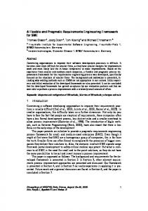
Page 2 PITFALLS IN FLEXIBILITY Sometimes the excess capability embodied in flexibility leads to problems when equipment is used out of context. (McNaugher 2000) discusses the fact that warriors use new equipment in ways that were not envisioned by designers or tested in formal testing. Although this was a tribute to the work of developers – their systems invited novel uses – it nonetheless could produce embarrassing and costly technical problems in their products. Some of the reliability and performance problems that plagued the US Air Force’s F-1000 engine, for example, stemmed from the engine’s remarkable power and resilience. Whereas the engine had been designed principally for speed, pilots of the new F-15, the first aircraft powered by the F-1000 engine, found operational advantage in rapidly changing speed, submitting the engine to "thermal cycles" not envisioned as the engine was designed and tested. This was one of several reasons the engine underwent nearly a decade’s worth of maturational development before reaching its full potential. CAPABILITY DRIVES REQUIREMENTS In the traditional acquisition process, a system that met the requirements was implemented within a set of constraints. However, the set of constraints did not include that of architecture, so the designers were free to build their system around “any” architecture. However in an age of “Design to Inventory” the designers now have to limit their implementation to something that exists within the relevant architectures. Thus the system engineer now has to identify non-existent capability within the architectural framework. This is done by an iterative process in the following manner. 1. Develop a set of operational scenarios or concepts for the SOS. 2. For each item (system) in the inventory, identify in which of the scenarios it can be used. 3. When done, draw a table similar to Table 1. Use an “X” to signify that the inventory item has capability that allows it to be used in the scenario. 4. Examine the rows and columns in the table. 5. Inventory items (rows) that have X’s marked in several columns are flexible items. 6. Any row that is a subset of another row contains an item that is less flexible than the other row and is a candidate for phasing out unless there are specific reasons for not doing so (i.e. much lower in cost or has additional capability not used in any of the scenarios)
INCOSE-UK Spring Symposium, May 2001
Inventory Item 1 A B C D E
X
X
Scenario 2 3 4 X X X X X X X X
Page 3
5 X X X X
Table 1 Capability of Inventory Items in Various Scenarios 7. Examine the capability of the items and use the total capability to postulate additional scenarios. These scenarios to be based on evolution of technology, changes to national objectives and threats, etc. 8. Add columns for the additional scenarios to the table. 9. Insert an “X” in the appropriate place for the items that can be used in the new scenarios. 10. Determine missing capability. 11. Start acquisition process for systems that would contain the missing capability (a column without an “X”). 12. Go back to step 6 This process is that of an evolutionary acquisition paradigm in which the SOS perspective is maintained. JUST IN TIME REQUIREMENTS Along with the evolutionary approach, some requirements must also be finalized using a just-intime (JIT) approach (Kasser 2000a). There are many scenarios in which the functionality required can be met by today’s technology and locking in a requirement to use the technology will lead to poor performance in the future. For example, systems have been delivered within the last year or so with built-in 386 processors. The requirements were written at a time when the 386 was the latest and greatest, but by the time of delivery technology had long since passed the 386. Now there may be good reasons for requiring specific instances of technology, however in most cases delaying the decision works in the interests of the customer. Delaying decisions is risky and such related decisions should be flagged in the project management information system to minimize risks. One example of the negative aspect of using fast processors is that software written in Borland’s Turbo Pascal may not run on fast processors due to delay loops embedded in the compiler failing to provide enough delay in the serial port interface in Pentium-based systems.
In general the process is to examine the situation to determine the level of risk. If the requirement can be met by a number of solutions, then the decision as to which solution to implement may be deferred. As an example, if the requirement is to provide a longdistance communications link, then it may be met using a variety of technologies such as communications satellite, H.F. radio, microwave link, optical fiber. If several of the technologies will meet the requirement there is little risk in delaying the decision and the capability provided by the technologies in existence at the time the decision will be made will probably provide the customer with a more flexible system (extra capability). THE BACKCASTING APPROACH Another way to identify and develop flexible systems is to work back from the solution. Traditionally we are taught to work forwards, in that several (implementation-free) designs are proposed in response to the requirements and the optimal solution is then chosen. An alternative is to work back from the solution. The process is 1. Visualize the system in operation. This is the operations concept. 2. Develop the system requirements 3. Identify the requirements that can be implemented in a JIT manner. 4. Identify the “don’t care” requirements 5. Identify the “don’t want” requirements 6. Pick a design that implements the “want” and “don’t want” requirements and tends not to inhibit the “don’t cares” 7. Design the system making JIT decisions Implementing a backcasting approach requires the three factors listed below. Since organizations with low Capability Maturity Model (CMM) levels probably do not have a suitable change control process, backcasting may only be appropriate for higher level CMM organizations. The thee factors are: •
A SOS attitude - External factors that could affect the system must be identified and monitored and changes to the project made as appropriate.
•
An effective change control process - The change control board must make sure that decisions are made in a timely manner.
•
The ability not to fixate on a single solution – something may happen during the implementation phase which may require the approach to be cancelled or significantly modified (e.g. technology break-through or change to mission/business directions). Should this situation arise, the CCB must act appropriately and not ignore the change in the context of the project.
INCOSE-UK Spring Symposium, May 2001 EXAMPLES OF FLEXIBLE AND NONFLEXIBLE SYSTEMS Consider the following sample of systems from the macro to the micro level. •
The Luz SEGS-1 Project
•
The National Aeronautics and Space Administration (NASA) Space Transport System
•
The Division Air Defense Sergeant York gun
•
The Standard Central Air Data Computer (SCADC)
•
The RCA Cosmac Microprocessor
•
The Joint Strike Fighter
The Luz SEGS-1 Project In the mid-1980’s the Luz Group, a start up joint Israel-American venture were developing the world's first commercial solarfueled electrical power generating system (SEGS-1). As the first of its kind, SEGS-1 initially only existed then as a vague concept. The station was to be installed in the Mojave Desert in California, but the Research and Development was to be in Jerusalem. SEGS 1 was intended to generate electrical power from the sun by focussing the sun's rays on about 600 parabolic mirror trough reflector collectors each about 40 meters long. The operation of each parabolic trough reflector was monitored and controlled by a microprocessor based local controller (LOC). Each LOC controlled a motor that positioned the parabola, and received information about the angle of elevation and the temperature of theoil in the pipe positioned at the focus of the trough. Oil was pumped through the piping, and as long as the LOC kept the reflector pointed at the sun (within an accuracy of +/- 0.2 degrees), the oil was heated. The hot oil was pumped thorough a heat exchanger to generate steam. The steam drove a turbine that generated up to 15 Mega Watts of electrical power. Although it was a complicated system, it still had a conversion efficiency of about 40%, greater than any alternative method of harnessing solar energy.
Page 4 •
There were no vibration specifications for the mirrors.
•
At that time, Jerusalem was at the end of a long delay in purchasing parts due to geographical distance. This meant that purchase orders for prototyping parts had to be placed before the designs were completed.
•
The engineers and technicians spoke various degrees of Russian, English, French, Romanian, and Hebrew, because most were immigrants and there were times when there was no common language in a meeting.
•
There were no production facilities for electronic circuits.
•
There were few if any quality control concepts.
•
There were few if any written specifications or procedures in the control and electronics department
•
There were some barely working prototypes.
The control system was designed by optimizing the system as a whole and allowing for uncertainty. Thus
•
The central computer predicted the approximate position of the sun and commanded the LOCS to deploy to the appropriate position.
•
The LOCs were designed as “state machines” (the states being - rest, deploying, acquiring, tracking, and stowing).
•
Each LOC was able to sense (acquire) the sun using the sun sensor mounted on the mirror.
•
Each LOC was able to follow the movement of the sun using a lead-lag algorithm to move along with the sun to “flywheel” during short periods of cloud cover. Transfering the pointing functionality from the central computer to the individual LOCs meant that the planned minicomputer could be replaced by a microcomputer. This approach avoided at least $US 300,000 in hardware and software costs. In addition if the control link failed the mirrors would continue to point at the sun. The sensors used to detect the elevation angle of the mirrors were absolute position indicators instead of relative indicators based on a revolution count. This design approach allowed the LOCs to recover in the event of power failures and spikes on the power line in the unknown E-M environment.
•
The communications approach between the central computer and the LOCs was based on a sequential polling approach at relatively slow speeds using shielded twisted pair connectors and human readable ASCII text messages. This approach allowed for servicing using palm held ASCII terminals that eliminated the
The situation was very uncertain (flexible), namely •
Control would be single axis (elevation) only.
•
Power generation efficiency dropped rapidly if the mirrors were not pointing at the sun. Actually the mirrors would radiate the heat instead of absorbing it under off-pointing conditions.
•
There were wide tolerances on the North-South alignment of collectors.
•
The electromagnetic (E-M) environment was unknown.
•
The sun sensors were mounted on the mirrors.
interference
INCOSE-UK Spring Symposium, May 2001 need to develop special test equipment. Low data rate speeds were valid because the movement of the mirrors was very slow, as was the rate of heating of the oil. However, there while the concept of flexibility worked well in the control and electronics area, it was not employed in other departments. The sun sensor provided an example of what can go wrong. The sun sensor used a lens to focus the sun onto a pair of photo diodes. During the assembly process, the diodes were glued to a baseplate with transparent glue. The physics department who were building the sun sensors did not place a requirement that there be no glue on the side of the diode illuminated by the sun. After all, the glue was transparent. A year or so later, they found that the glue slowly became opaque when subjected daily to the very high temperature at the focal point of the lens. This phenomenon resulted in the need to replace all the sun sensors. From a manufacturing perspective, there was little difference in mounting the diodes if the glue could or could not be allowed to cover the face of the diode, just a matter of care. Nobody asked about possible changes to the characteristics of the glue over long periods of time under high temperature. If the requirement had been placed on the process, not to allow glue on the face of the diode, the characteristics of the glue under the high temperature conditions would not have mattered and the expensive sun-sensor replacements would have been avoided (Kasser 1995). This is an example of introducing an unnecessary failure mode by not utilizing the “don’t cares”. Thus if it doesn’t make any difference don’t do it. The National Aeronautics and Space Administration (NASA) Space Transport System. The Space Transportation System commonly known, as the space shuttle is an example of an approach to designing a flexible system based on the assumption that “one size fits all”. Concerned about the cost of expendable vehicles in an era when space flights were anticipated to become commonplace, NASA intended to reduce costs by designing a single reusable vehicle. The result was an expensive vehicle and not entirely reusable since expendable parts (booster and fuel tanks) are employed. Experience has shown that one size does not necessarily fit all and a more flexible solution may be expendable cargo carriers and a small reusable manned vehicle. The manned vehicle to be a single stage to orbit type of vehicle with the support requirements of a commercial passenger jet aircraft. However such a solution for the shuttle replacement may still not be politically correct since NASA has a large investment in manned mission support. In a sense, since NASA does launch both the shuttle and expendable vehicles, they have implemented a mixed solution but at significantly greater cost than a system designed for the mixed scenario. Once on-orbit-docking capability had become
Page 5 routine, the mixed launcher solution became very viable from a technical perspective. Yet the political impact of the reduction in support staff is a pertinent issue that seemingly remains. The shuttle fleet is aging and no replacement program has been announced even with the commitment to support the Space Station. The Division Air Defense Sergeant York Gun. The Division Air Defense gun (DIVAD) program was initiated by the US Army's need for a replacement for the aging M163 20mm Vulcan A/A gun and M48 Chaparral missile systems (Pike 1999). The new selfpropelled anti-aircraft gun system was to be based on the M48A5 tank chassis, using as much off-the-shelf equipment as possible. After examining two designs, Ford Aerospace and Communications Corporation (FACC) was selected as the contractor in May 1981 and the gun was designated as the M247 Sergeant York. FACC’s design was based on the reuse of two additional existing systems (capability) namely •
The weapons - twin 40mm L/70 Bofors Guns.
•
The radar - a modified version of the Westinghouse APG-66 system used in the F-16 Fighting Falcon.
The program suffered from problems, and by the delivery of the first production vehicles in 1983 many problems remained, including •
The radar's inability to track low flying targets due to excessive ground clutter. The radar could not distinguish between a hovering helicopter and a clump of trees.
•
When tracking highflying targets, the radar return from the gun barrel tips confused the fire control system. Turret traverse was also too slow to track a fast crossing target.
•
The ECM (electronic counter-measures) suite could be defeated by only minor jamming.
•
The use of the 30 year old M48 chassis design meant the vehicle had trouble keeping pace with the newer M1 Abrams and M2/3 Bradley's, the very vehicles it was designed to protect. These problems proved insurmountable, and in December 1986 after about 50 vehicles had been produced the entire program was terminated. The Standard Central Air Data Computer (SCADC). The SCADC project (Howard 2001) was one of about a dozen standardization programs initiated in the late 1970's by the US Defense department in the desire to obtain substantial reductions in equipment life-cycle costs through the wide use of digital common modules in aircraft.It was thought that SCADC, because of the complexity and accuracy requirements of air data computation, would be a difficult concept to bring to fruition. In addition, the SCADC program required the delivery
INCOSE-UK Spring Symposium, May 2001 of up to 150 units per month shared between two winning suppliers, in a continuously competitive leader-follower arrange-ment. Two of the three largest US suppliers of airborne air-data systems, Honeywell and Sperry declared the concept impossible and declined to bid, despite the potential of $500 million of business. GEC Avionics in the UK were interested in the business and designed and built a SCADC in a replacement form fit-function for the then existing analogue components. The system was a modular core set of standard Air Data Computer modules made extendable by the use of the 1553 data bus. The ability to replace “old for new" in around 30 minutes on thousands of the older inventory aircraft, raising the MTBF rates from 100 hours to greater than aircraft life-times and at the same time equipping them for plug-in new attack systems (via the 1553 data bus) was a significant technical innovation. However, it also had the effect of putting many logistics people out of work overnight. When the first prototypes were demonstrated, a huge effort was launched in Washington by the Logistics fraternity to have the project cancelled. This was supported by much of the US industry who could see an outcome that depleted a large portion of their diverse business with the danger of much of it going overseas. Although the SCADC production programs continued, the implementation in service was delayed for up to two years. Another casualty was that all the other standardization programs fell by the wayside. By 1998, 6000 units in various configurations had been sold including a version now modified into a digital flight control system adopted by the US Navy for the F14. It was the most widely used digital system and most reliable in all aircraft in the Gulf War. The program was arguably the most successful of any airborne equipment supply program in the history of world aerospace, and 100% of the production units came from the UK source, the leader-follower concept being abandoned. It was estimated that by the time GEC Avionics received the third or fourth order for production units, the direct Defense savings exceeded $US 500 million. The RCA Cosmac Microprocessor. The Cosmac was the first 8 bit CMOS microprocessor in the days when all the rest were NMOS (mid 1970’s). It was ideal for environments in which the low power and other characteristics of CMOS were desirable. However, it was less than a success. The hardware circuitry was simple to use, however, the software architecture was extremely flexible. It was so flexible that any register could be programmed to serve any function. Most people ended up using the device in fixed configurations and did not take advantage of the flexibility provided by RCA.
Page 6 The Joint Strike Fighter. The Joint Strike Fighter (JSF) is a multi-role fighter optimized for the air-toground role, designed to affordably meet the needs of the US Air Force (USAF), Navy (USN), Marine Corps (USMC) and allies, with improved survivability, precision engagement capability, the mobility necessary for future joint operations, and the reduced life cycle costs associated with tomorrow’s fiscal environment. The JSF will benefit from many of the same technologies developed for F-22 and will capitalize on commonality and modularity to maximize affordability (Pike 2000). The JSF program will demonstrate two competing weapon system concepts for a tri-service family of aircraft to affordably meet these service needs. However the needs are different as summarized in Table 2, namely •
The USAF. The USAF wants a multi-role aircraft (primarily air-to-ground) to replace F-16 and A-10 and to complement F-22. The USAF JSF variant poses the smallest relative engineering challenge. The aircraft has no hover criteria to satisfy, and the characteristics and handling qualities associated with carrier operations do not come into play. As the biggest customer for the JSF, the service will not accept a multirole F-16 fighter replacement that doesn't significantly improve on the original.
•
The USN. The USN wants a multi-role, stealthy strike fighter to complement F/A-18E/F. Carrier operations account for most of the differences between the Navy version and the other JSF variants. The aircraft has
•
•
Larger wing and tail control surfaces to better manage low-speed approaches.
•
A strengthened internal structure to handle the loads associated with catapult launches and arrested landings.
•
A carrier-suitable tail hook.
•
Landing gear with a longer stroke and higher load capacity.
•
Has almost twice the range of an F-18C on internal fuel.
•
The design survivability.
is
also
optimized
for
The USMC. The USMC wants a multi-role Short Take-Off & Vertical Landing (STOVL) strike fighter to replace AV-8B and F/A18A/C/D. The Marine variant distinguishes itself from the other variants with its short takeoff/vertical landing capability.
INCOSE-UK Spring Symposium, May 2001
Service U.S. Air Force U.S. Marine Corps Royal Navy U.S. Navy
Page 7
Variant Conventional Takeoff and Landing (CTOL) Short Takeoff and Vertical Landing (STOVL)
Cost FY94 US$ $28M $35M
Carrier-based (CV)
$38M
Table 2 JSF Variants
•
The UK. The UK is looking for a STOVL (supersonic) aircraft to replace the Sea Harrier. The Royal Navy’s JSF will be very similar to the USMC variant.
The JSF concept is building these three highly common variants on the same production line using flexible manufacturing technology. Cost benefits are expected to result from using a flexible manufacturing approach and common subsystems to gain economies of scale. Cost commonality is projected in the range of 70-90 percent; parts commonality will be lower, but emphasis is on commonality in the higher-priced parts. LESSON LEARNED FROM THESE SYSTEMS Various, lessons can be learnt from these systems including •
Programs do not fail because the requirements change, programs fail due to poor change management.
•
There are risks when using capability in ways for which it was not designed.
•
Political factors
•
The SOS environment must be taken into account.
•
Too much flexibility can be worse than no flexibility.
considerations
outweigh
technical
Programs do not fail because the requirements change, programs fail due to poor change management. This reinforces the observation that programs do not fail2 because the requirements change (Kasser 2001). The tasks, products, and processes for managing change exist and have done so for over 20 years3. Programs fail because of poor requirements engineering management and the failure to reevaluate requirements in the context of •
Changes in needs.
2 Failure is defined as [cancelled] or [incur > 60% (cost or schedule) over-runs]. 3 The US Military standards cover the ground in more than enough detail.
•
Changes in technology.
•
Changes in paradigm. The effect of air power on battleships was noted in World War II. Today a paradigm shift is taking place due to the development of low cost guided ordnance. Their effect of expensive aircraft and surface ships has yet to be fully determined.
There are risks when using capability in ways for which it was not designed. These range from the USAF’s F-1000 engine to the DIVAD. In the DIVAD the integration of three systems produced an array of technical and operational test difficulties that ultimately led to its cancellation. Some of these difficulties might have been prevented had the situation been different. For example, the pilots must have known about the problems with the flight radar at low altitudes, yet the information was not passed to FACC or the selection board. There is thus a need for domain expertise when attempting to use capability outside its original environment. In addition, four successive generations of upgraded US forward area air defense systems - from Mauler to Roland to Sgt. York to ADATS - were all canceled, at a total cost of more than $6.7 billion over a period of 30 years (Pike 1999). What does this mean in an evolutionary acquisition paradigm in an era of extending systems operational lifespan? Political considerations outweigh technical factors. This lesson reinforces the findings of (Kasser and Williams 1998). The optimal technical solution may be resisted for political reasons, as in the SCADC and space shuttle programs. The SOS environment must be taken into account. The advances in the vehicles the DIVAD was to support would have been observed and affected the program had the project considered changes in the SOS environment.
INCOSE-UK Spring Symposium, May 2001 Not only must the SOS environment must be taken into account, but the project must focus on the real needs not the solution unlike in the DIVAD program. Take Manned Aircraft as another example. In WWI they provided ability to see over the horizon and bring back information about enemy dispositions. Then each side added guns to stop the enemy from doing the same. This led to squadrons of fighter aircraft fighting each other but in reality doing little to advance the war effort. Guns also allowed ground support, which led to ordinance delivery on the trenches and behind the lines. These situations led to specialized types of aircraft, complex onboard computers, and latterly to the JSF. Yet the question that really needs to be asked is what are today’s real mission requirements and can they be met without manned aircraft? Too much flexibility can be worse than no flexibility. In this situation the frame of reference is lost and the flexibility ends up providing too many choices. This is probably why the RCA Cosmac microprocessor failed to be adopted widely. CONCLUSIONS The conclusions from this study are that •
Writing requirements for flexible systems is not easy and is pointless unless effective intelligent change management tools are developed and used: tools such as the FREDDIE concept (Kasser 2000).
•
History repeats itself. The JSF is doomed to cost and schedule overruns due to the lack of intelligent change management tools as well as the political considerations involved.
•
The JSF may also be doomed in threat environments due to failure to recognize paradigm shift due to the introduction of guided ordnance.
•
One size does not fit all, several may be required.
•
The amount of flexibililty or excess capability incorporated into a system needs very careful consideration.
REFERENCES Allison, J.S., Cook S.C, “The New Era in Military Systems Thinking and Practice”, Proceedings of the First Regional Symposium of the Systems Engineering Society of Australia INCOSE Region 6 (SETE 98), Canberra, Australia, 1998. Howard, R., personal correspondence to J Kasser, 1 April 2001. Pike J., M247 Sergeant York DIVAD, 1999, http://www.fas.org/man/dod-101/ sys/land/m247.htm, last accessed April 5, 2001.
Page 8 Pike, J., Joint Strike Fighter (JSF), http://www.fas.org/man/dod-101/ sys/ac/jsf.htm, last accessed April 5, 2001. Kasser, J.E, Williams, V.R., “What Do You Mean You Can’t Tell Me If My Project Is in Trouble?”, First European Conference on Software Metrics (FESMA 98), Antwerp, Belgium, 1998. Kasser, J.E., Applying Total Quality Management to Systems Engineering, Artech House, June 1995. Kasser, J.E., “A Framework for Requirements Engineering in a Digital Integrated Environment (FREDIE)” the Systems Engineering Test and Evaluation Conference, SETE 2000, Brisbane, Australia, 2000. Kasser, J.E., The WebConference: A Case Study, The INCOSE - Mid-Atlantic Regional Conference, Reston, VA, 2000 Kasser, J.E., Course notes for Requirements Engineering, postgraduate subject at the University of South Australia, 2001. McNaugher, T.L., “Risks and Rushing: The Causes and Costs of Production Concurrency”, Statement prepared for the House Committee on Government Reform, Subcommittee on National Security, Veterans Affairs, and International Relations, hearings entitled Joint Strike Fighter (JSF) Acquisition Reform: Will It Fly? May 10, 2000, http://www.fas.org/man/ congress/2000/000510mcnaugher_may_10.htm, last accessed April 5, 2001.
BIOGRAPHY Joseph Kasser D.Sc. C.Eng, CM, has been a practicing systems engineer for 30 years. He is the author of "Applying Total Quality Management to Systems Engineering" published by Artech House. Dr. Kasser is both a DSTO Associate Research Professor at the University of South Australia (UniSA) and a Distance Education Fellow in the University System of Maryland. He performs research into improving the acquisition process. Prior to taking up his position at UniSA, he was a Director of Information and Technical Studies at the Graduate School of Management and Technology at University of Maryland University College. There, he developed and was responsible for the Master of Software Engineering degree and the Software Development Management track of the Master of Science in Computer Systems Management (CSMN) degree. He is a recipient of NASA’s Manned Space Flight Awareness Award for quality and technical excellence (Silver Snoopy), for performing and directing systems engineering. Dr. Kasser also teaches systems and software engineering in the classroom and via distance education.