Proceedings of IDMME - Virtual Concept 2010 Bordeaux, France, October 20 – 22, 2010
Original Article
HOME
XAML-based usability assessment for prototyping information appliances with touch sensitive interfaces Satoshi Kanai 1, Taiga Higuchi1 and Yukiaki Kikuta 2
(1) : Graduate School of Information Science and Technology, Hokkaido University Kita-14, Nishi-9, Sapporo 060-0814, Japan Phone +81-11-706-6448 / Fax +81-11-706-6448 E-mail :
[email protected]
Abstract: Advanced systems for user interface prototyping, user test and usability assessment are proposed which enables 3D digital prototyping of information appliances with touch sensitive interfaces and automated user test and usability assessment. The 3D digital prototype was defined by XAML which is an XML-based user interface (UI) markup language. Not only UI elements, data binding and event routing but 3D geometric model of the appliance can be defined by XAML. The specification of XAML was extended to enable declarative description of dynamic behaviour of the UI. A gesture recognition function enabled the users to manipulate the touchsensitive UI on 3D digital prototypes in the user test. Execution of user tests and analysis of missed operations could be fully automated. A case study of the user test and usability assessment of a digital camera showed an effectiveness of the 3D digital prototyping in efficient usability-conscious design. Key words: user interface, prototyping, usability, XAML, information appliances, touch-sensitive interface, usability-conscious design. 1- Introduction
With stiffer global market competition of information appliances, usability-conscious design while shortening the lead time have been required in the manufactures. Prototyping and user-test by end users at early design stage are recognized as the most objective and effective method to fulfill the requirement. Usually, physical prototypes in which the user interface (UI) functions of appliances are implemented are used for the user-test. However, fabricating the physical prototypes costs much, and they become available only in late stage of the design. Results of the user-test must be analyzed manually by the usability engineers, and a long turnaround time is needed before finding major usability problems. To solve the problems, digital prototyping of the UI was introduced in the user-test. A digital prototype is software substitute where its UI functions can work in the same way as those in the physical prototype while it can be built in more inexpensive way.
PRIDE_P189
-1-
(2) : System Brain, Ltd. Sakae-Dori 9-5-8, Shiroishi-ku, Sapporo 003-0021 JAPAN Phone +81-11-851-9994 E-mail :
[email protected]
So far, both 2D and 3D digital prototypes have been proposed and used for the purpose. Commercial digital prototyping tools have been already available such as [MA1]. And those for conceptual UI design were also studied in [LN1, LM1]. However, since 2D digital prototypes could only be built in these tools and its UI simulation were only limited to 2D and lacked reality, the user performance obtained from these prototypes were not necessarily the same as those of physical prototypes. Former studies including ours [KH1, PM1] showed that operation time and missed operation patterns in a 2D digital prototype were very different from those of the physical prototype and serious usability’s problems were overlooked in 2D case. On the other hand, “3D” digital prototypes allows users to manipulate UI elements placed on 3D housing models of the appliances and to perform more realistic UI simulation than 2D ones. In our former study [KH1], the missed operation patterns in a 3D digital prototype were also highly correlative to those of the real product. Unfortunately, there have been few dedicated tools of 3D digital prototyping for information appliances [KB1, KH1, PM1]. In [KB1], they added a logging function to a VRML player and applied it to the user test of mobile phones. In [KH1], they added a state-based UI simulation function and usability assessment function to a commercial Web3D player and applied it to the test of digital camera. In [PM1], they developed a tool for 3D augmented prototyping for some hand held information appliances with state-based UI simulation. However, these tools had the following technical drawbacks; First, structure of 2D UI components such as menus and icons could not be declaratively modeled and not be directly rendered in the tools. As a result, every UI screen had to be rendered as a texture-mapped image on the 3D prototype, and huge number of UI screen snapshots had to be drawn manually in some paint tools when building digital prototypes. These preparatory works make prototyping turnaround very inefficient. Second, the description of dynamic behaviors of the UI could not be compatible with interaction designer’s
Copyright of IDMME - Virtual Concept
IDMME - Virtual Concept 2010
XAML-based usability assessment for prototyping information appliances
UI Design UI Prototyping 3D CAD (Solidworks, etc.)
Our developed system Gesture Recognition Engine
3D Housing Data (XAML)
Prototype Contents
UI Component Data (XAML)
Finger Gestures Touch Panel LCD
General Event
UI Screen Data (XAML) UI Behavior Data (XAML-B)
XAML-B Execution System (C#)
Action 3D UI Simulation System(C#)
• Task statement • Questionnaires
• Test Task (XML)
• Five grade answers of questionnaires • Operational log file • Performance Measure • Operational Log Analysis Chart
User Test Execution System (VB) Test Task UI デザイン Definition System (Visio +VB)
State-based Model
Commercial system
Integration System (Expression Blend)
Draw Tool (Illustrator, etc.)
Dynamic Behavior Modeling System (Visio + VB)
Finger Gesture Event
Test Task & Correct Operation Sequence (XML)
User Testing and Usability Assessment
Event-based Model
XAML-B
Usability Analysis System(VB)
Figure 2. UML class diagram of XAML-B Figure 1. An overview of the proposed XAML-based 3D digital prototyping and usability assessment systems
-
ability. The dynamic behavior means how icons or menus behave and change in response to input events. In the tool [KB1], the behavior must be defined by a programming language which is not UI designer’s strong points. While, in the tool of [KH1, PM1], it could be modeled as a state machine [HO1], but it may cause state explosion in description as the size of the behavior increases. Third, these previous tools did not support simulation of touch sensitive interface which becomes very common in recent appliance UIs such as i-Pod and digital cameras.
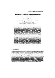
In order to solve these problems, the purpose of this paper is to develop advanced systems of user interface prototyping and usability assessment. As shown in Figure 1, the proposed systems enable 3D digital prototyping of information appliances with touch sensitive interfaces and also enable automated user test and usability assessment. The 3D digital prototype is defined by the combination of XAML and XAML-B which is our original extension of XAML. The technical features of the proposed systems are summarized as the followings; - XAML allows UI designers to declaratively describe static structures both of 2D UI components and 3D housing, and its vector-graphic rendering engine can generate highquality UI images on-the-fly. So, pre-generation of snapshot images of UI screen becomes unnecessary. - The proposed XAML-B enables UI designers to declaratively describe dynamic behaviors as a set of eventbased rules. It can eliminate their programming works and state explosion in the UI behavior modeling. - A standard PC environment is only needed for 3D UI simulation. Any special Web3D player is unnecessary. - The processes of the user test and the usability assessment are fully automated along with the 3D digital prototype. - Gesture recognition function enables the users to manipulate touch-sensitive UI on the 3D digital prototype.
PRIDE_P189
-2-
2- XAML-based 3D UI Prototyping 2.1 –XAML
XAML (eXtensible Application Markup Language) was developed by Microsoft [MV1] as a UI specification targeted for Windows applications. XAML is an XML based mark-up language which specifies the static structure of a UI running on the WPF (Windows Presentation Foundation). WPF is a UI framework to create applications with a rich user experience, and combines applications UIs, 2D graphics and 3D graphics and multimedia into one framework. Its vectorgraphic rendering engine makes the UI implementation fast, scalable and resolution independent. WPF separates the appearance of an UI from its behavior. The static structures of 2D UI screen appearances is declaratively specified in XAML, while the behavior has to be implemented in a managed programming language like C#. 2.2 – XAML-B for dynamic behavior modeling 2.2.1 – Modeling Concept of XAML-B
We extended XAML specification so that the UI designers can declaratively define dynamic behavior only by writing a XML document with simple syntax. This extension part of the XAML is named XAML-B (XAML-Behavior). We also proposed a two-stage modeling process of dynamic behaviors both of which is supported by XAML and XAMLB. In these stages, two sub-models of XAML-B were respectively used to define the dynamic behavior; the statebased model for early design stage and the event-based model for detailed design stage. The UML diagram describing class structures of XAML-B is shown in Figure 2. The specification of the XAML-B includes both state-based model, event-based model and the reference to the original
Copyright IDMME - Virtual Concept
IDMME - Virtual Concept 2010
XAML-based usability assessment for prototyping information appliances
Parent_state
Event
State
Power_On
Power button pushed / Turn on LCD & Turn on Lump 1
Power off
(1) Capturing Rough Interaction Flows
State
Rec mode
Early Design Stage
State‐based model (XAML‐B)
(Current_state)
Rec_Mode
(Next_state)
Power_Off
Action
(a) State-based model Event UI Element Housing Design properties Cv Screen Design properties
AF_Mode
Behavior Power button pushed
Reading
Lhs
Static Structure (XAML)
Rhs
Detailed Design Stage
Behavior
Behavior (property updating conditions)
Power off
Turn on LCD & Turn on Lump 1
Writing
( properties to be updated)
Event-based Model
Rec mode
Current_state
Next_state
State-based Model
(b) Event-based model in XAML-B
(c) Implementation
State: Power Off
LCD
(3) Extracting change rules in the attribute values of XAML at a screen transition
(2) Assigning XAML tags and attribute values to each state
Dynamic Behavior (XAML-B)
Power button
State-transition Editor (Visio +VB)
Action
UI Screen Data (XAML)
Lump1
Power_Off
State Assignment Data (XML)
Figure 4. Examples of state-based modelling and event-based modeling of UI behaviors Rec_Mode
(4) Reformatting the change rules to XAML-B Dynamic Behavior model expressed only by event‐based model (XAML‐B)
State: Power On, Rec mode
Figure 4. Dynamic behavior modeling process in the modeling system
Figure 3. Examples of state-based modeling and event-based modeling of UI behaviors
XAML specifications. The details of these two models are based dynamic behavior. A set of the classes of XAML-B included inside the event-based model in Figure 2 is used. explained as the following sub-sections. The event-based model consists of Behaviour, Lhs, Action and Event. Notions of Behaviour, Action and Event are the 2.2.2 – State-based model for early design stage same as those in the state-based model. An Lhs expresses the At the early design stage, the dynamic behavior of the UI is conditions under which each Action become executable. An modeled as a state-based model, because the number of states Action consists of the combination of MethodCall and Rhs. is relatively small and the state-based model enables UI An Rhs specifies how the attribute values of XAML should designers to capture a flow of user interactions at a glance. change corresponding to the change of UI appearance. A Rough interaction flows of the UI are initially captured as a MethodCall specifies an external procedure such as an state-based model. animation clip or a sound clip. A pair of an Lhs and an Rhs Figure 3-(a) shows an example of the state-based model in case describes a state-transition rule. And a RuleTerm expresses a of the power-on UI behavior in a digital camera. A set of the condition that attribute values in XAML must fulfill before classes of XAML-B included inside the state-based model in and after an Action occurs. Figure 2 is used. The state-based model consists of the classes of State, Event, Behavior and Action. 2.3 – Dynamic behavior modeling system and the A State expresses unique combination of attribute values which modeling process expresses an appearance of the UI. An Event is an incoming phenomenon to the UI such as “button-pushed” or “icon- We developed a prototype of dynamic behavior modeling tapped”. An Action is a process triggered by an event that system which was implemented by the combination of Visio causes a state change such as change in an icon on the screen and Visual Basic. Figure 4 shows the functions of the or mechanical motion of the appliance. A Behavior means a modeling system. It can support both of the state-based and notion of state-transition composed of Source_State, event-based modeling processes. The modeling flow of the system is also shown in Figure 4. Destination_State, Event and Action. In the early design stage, as in the upper part of Figure 4, 2.2.3 – Event-based model for detailed design stage rough interaction flows are initially captured as a state-based model. In order to support efficient modeling work in this Once the UI design enters the detailed design stage, the stage, a state-transition editor was implemented. In the editor, number of states tends to explode when using the state-based state, event and action can be graphically created and edited model. So, an event-based model is used at the detail design on the Visio by UI designer. This modeling result is stored in stage. The event-based model enables the designers to describe a XAML-B document. the detail control of UI components indicated on the screen In the detailed design stage, as shown in the lower part of whose notion is originally included in XAML specification. Figure 4, first a set of tags and their attribute values of one Figure 3-(b) shows an example of the event-based model UI screen which has been modeled as XAML document in which is described based on the state-based model example of the integration tool are assigned to one state. A new state tag Figure 3-(a). The event-based model was made up on the basis is created in the XAML-B document, and a set of the XAML of UsiXML [VJ1], which is the other XML-compliant UI tags and their attribute values representing the state of the UI description language and has declarative description of event- is packed inside the state tag. Two different sets of these tags and the attribute values each of which is assigned to a
PRIDE_P189
-3-
Copyright IDMME - Virtual Concept
IDMME - Virtual Concept 2010
XAML-based usability assessment for prototyping information appliances
source or a destination state are then compared to each other. Taking XOR between these tags and attribute values automatically makes the change in attribute values of an Action tag in the event-based model. Finally reformatting the rule of change to an XML document makes a final XAML-B description corresponding to this state-transition. 2.4 – Building process of 3D digital prototype
Test Task Turn on the Power Digital Questionnaire based on HCI model
Answer the following question on the task just taken by you.
UI Element Indicator
Strongly agree Agree Yes and No Disagree Strongly Disagree
Did you soon notice According to the process described in 2.3, a 3D digital this icon ? prototype is built in the following processes shown in Figure 2; 1) A 3D housing model is created in a commercial CAD 3D Digital Prototype 5 Grade Rating Button A Questionnaire system (Solidworks 2008) and is exported to a model integration system (Expression Blend) as a XAML Figure 5. User test situation and the digital document. questionnaire using the 3D digital prototype 2) Each graphical component (text, icon, etc.) of the UI is defined in a draw tool (Illustrator etc.) and is exported to of task routes. And a task route consists of a list of an integration tool as a XAML document. checkpoints. A checkpoint is a state where a correct 3) In the integration tool, a set of the graphical components sequence of UI operation must pass. are combined to make one XAML document which 2) As shown in Figure 5, at the beginning of the user test, a defines each UI screen. And the 3D location of the UI 3D digital prototype and a task statement are indicated to screen is also specified onto the 3D housing model by this the user, and a user is asked to complete the task by XAML document. operating the 3D UI of the prototype using a touch 4) The XAML document is imported to a dynamic behavior screen display or a mouse. The actual operation modeling system. The behavior of the UI is defined by a sequence including event sequence actually inputted by UI designer according to the process described in 2.3, and the user and state sequence through which the system is outputted as a XAML-B document from the system. actually passed are recorded in the operation log file. 5) Finally, the XAML-B execution system reads this 3) Every time a user completes or gives up completing a document and drives UI simulation on the 3D housing task, the recorded actual operation sequence is compared model responding to input events coming from the user of to the correct operation sequence. As shown in the the digital prototype. Figure 5, if the user took a missed operation, the system automatically indicate a set of questionnaires to the user 2.5 – Gesture recognition function in order to reveal the causes of the missed operation at every state where the user took a mistake. Gestural interfaces become available in current information The set of the questionnaires consist of six questions appliances with touch sensitive interfaces. So a gesture each of which corresponds to one of human cognition recognition function is installed in our prototyping system. steps proposed in HCI model (perception of objects, Several types of user finger gestures inputted from a UI screen perception of actions, etc.)[ND1]. An example of the of a 3D digital prototype can be recognized as events, and can questions is “Did you soon notice this button?” which is be processed in the XAML-B execution system. In the aimed for examining where the step of “perception of XAML-B specification, several gesture types that the function objects” was done well. The user is asked to rank every can recognize are described in the “Gesture_Type” attribute question in five grade evaluation. Their grade results can placed inside the “Event” tag. reveal which part of the human cognition process was Real-time gesture recognition is needed for smooth operation unsuccessful in the current UI design. The detail of this of UI simulation. InkGesture engine [IG1] is being used in the questionnaire-based test is described in our previous system. Four types of finger gestures of “Leftward”, paper [KH1]. “Rightward”, “Upward” and “Downward” can be recognized as Events in our system. The recognized gesture can then be 4) After finishing the user tests for all tasks, the operation log file and the results of the five grade evaluation in the processed as one of the events in XAML-B execution system. questionnaire are exported as XML files for further This recognition function enables the users to operate touch usability analysis. sensitive interfaces modeled on the 3D digital prototype using 5) In usability analysis system, task completion time and not only mouse gestures but direct finger gestures. task completion ratio among the subjects are automatically calculated from the operational log file and the test task model. The missed operational pattern 3- User test and usability assessment systems is also rendered as an operational log analysis chart In our system, user test and usability assessment can be done which schematically clarifies at which state the subject on the 3D digital prototype. The test and assessment processes frequently took the missed operation [KH1]. The are as same as the ones described in our previous paper [KH1] statistics of the five grade evaluation results by the users and are done in the following procedures; who took the mistake are also indicated at each state of 1) In a pre-process, a “task” which includes a set of correct the test task. operational sequences is defined in the test task definition system. A task consists of a start state, goal state and a list
PRIDE_P189
-4-
Copyright IDMME - Virtual Concept
IDMME - Virtual Concept 2010
XAML-based usability assessment for prototyping information appliances Task description
Task1
Set the self‐ timer duration for 10 sec from power‐off state
# of correct routes
Correct operation sequence and states at which digital questionnaires appear State
1
Task2
4- A case study of user test
Enter preview mode from a power‐off state, and display the pre‐specified picture on the touch screen using finger gesture
1
Timer Select Push 10s icon
Timer_10s
Power off Push power button
Shooting Push playback icon
Play_Mode Slide a finger horizontally
Play_First
Power off Push power button
Shooting Push home icon
Home Push playback icon
Play_Mode Slide a finger horizontally
Correct operati on
State
2
Shooting Push timer icon
Correct operati on
State
Figure 6. A digital camera and its digital prototype
Power off Push power button
Correct operati on
4.1 – An example of the 3D digital prototype
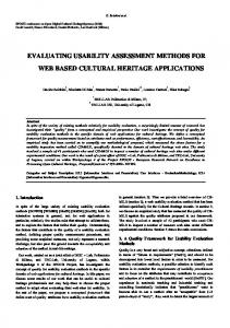
Figure 7. The test tasks and their correct operations A digital camera (Nikon-S60) with a touch-sensitive screen shown in Figure 6-(a) was adopted as an example of prototyping, user test and usability assessment. As shown in Figure 6-(b), the 3D housing model of the camera was modeled in Solidworks 2008. Over 60 states and 100 state transitions were modeled in the dynamic behavior model described by XAML-B. The sound of finger touch is also emulated in the digital prototype to avoid missed-operations. A 19-inch touch sensitive LCD monitor shown was used in the # of Subjects: 18 test, and the user can directly input by finger touch and finger Task Completion Rate 94.4% Average Grading for Questionnaires gesture on the touch screen displayed as a part of the 3D digital # of Subjects who answered Did you soon notice this icon ? 12 2.25 Questionnaires prototype which is displayed on the touch sensitive LCD Did you soon understand that 2.25 you should operate this icon ? monitor. This enabled the users to operate the UI on the 3D (a) Analysis Chart of Real Product digital prototype as realistically as the one on the real camera. 4.2 – User test settings
The user test was done using the 3D digital prototype and the operational log analysis chart and five grade evaluation results were compared to those obtained from the one using the real camera. 35 subjects who had no experience of using this camera attended the test. Among them, 17 subjects operated the 3D digital prototype and 18 subjects the real camera. Two tasks shown in Figure 7 which include the basic UI operations were given to the subjects. In task 1, they asked to set the self-timer duration for 10 sec from the power-off state. In task 2, they asked to enter the preview mode state from a power-off state and to indicate the first picture by turning over the pictures indicated on the touch screen. In the task 2, two correct sequences of operations exist as shown in Figure 7; the one of pushing an up-arrow or a down-arrow icon indicated at the corner of the touch screen, or the one of directly sliding the finger leftward or rightward on the touch screen. The five grade evaluation results for the questionnaires were also obtained from the subjects who took a missed operation.
# of Subjects: Task Completion Rate # of Subjects who answered Questionnaires
(b) Analysis Chart of 3D Digital Prototype
17 100% 9
Average Grading for Questionnaires Did you soon notice this icon ?
2.4
Did you soon understand that you should operate this icon ?
3.2
Figure 8. The operational log analysis charts and five grade evaluation results in Task 1
From Figure 8, it was found that many subjects (12/18 in case of real camera, and 9/17 persons in case of digital prototype) took missed operations at the “Shooting” state. In this state, they should push the small timer icon indicated lower left of the touch screen, but they found themselves lost deep in the menu hierarchy toward incorrect states. Two missed-operation patterns in Figure 8(a) and (b) were very similar to each other. Moreover, the results of the five grade evaluation for the questionnaire at the “Shooting” state 4.3 – Usability assessment results showed that most of the missed subjects did not notice the The operational log analysis charts and 5 grade evaluation icon to be pushed and did not understand that they should results for the questionnaires at a state of missed-operation in operate it. This figure also showed that same tendencies of case of the real product and the digital prototype in task 1 are the evaluation results were observed both in the digital shown in Figure 8. prototype and in the real camera.
PRIDE_P189
-5-
Copyright IDMME - Virtual Concept
IDMME - Virtual Concept 2010
XAML-based usability assessment for prototyping information appliances
(a) Operational Log Analysis Chart of the redesigned 3D Digital Prototype
(a) Operational Log Analysis Chart of Real Product and 3D Digital Prototype
Added animation
# of Subjects: # of Subjects: Task Completion Rate # of Subjects who answered Questionnaires
Task Completion Rate
100%
Did you soon understand that you should input finger gestures? Did you soon understand how you should make finger gestures? (ex. slide a finger horizontally etc.)
Task Completion Rate
100%
# of Subjects who answered Questionnaires
8
# of Subjects who answered Questionnaires
8
1.75 2 2.75
(b) Average Grading for Questionnaires in Real Product
5.0 100% 1
5.0
Did you soon understand that you should input finger gestures?
4.0
Did you soon understand how you should make finger gestures? (ex. slide a finger horizontally etc.)
4.0
(b) Average Grading for Questionnaires in the redesigned 3D Digital Prototype
Average Grading for Questionnaires
Average Grading for Questionnaires Did you soon notice the gesture input ?
10
# of Subjects:
10
Average Grading for Questionnaires Did you soon notice the gesture input ?
Did you soon notice the gesture input ?
2
Did you soon understand that you should input finger gestures?
2
Did you soon understand how you should make finger gestures? (ex. slide a finger horizontally etc.)
2
Figure 10. The operational log analysis charts and five grade evaluation results in Task 2 after UI redesign
(c) Average Grading for Questionnaires in 3D Digital Prototype
Figure 9. The operational log analysis charts and five grade evaluation results in Task 2
enabled UI designers to realize very rapid turnaround of design-test cycle compared to the one of physical prototypes. 5- Conclusions
While in case of the task 2, as shown in Figure 9, most of the subjects (8/10 in the real camera and in the digital prototype) did not complete the task using the finger gestures, but could it by taking alternative correct operation (pushing the icons). The five grade evaluation results for the questionnaire at the “Play_Mode” state also showed that the subject who took this alternative operation (“Play_Mode” “Play_Detail” “Play First”) did not notice that the camera could accept direct finger gestures and that they should make them to complete the task. These test results showed the following clear facts: - In the “Shooting” state and the “Play_Mode” state, the icon indicated on the UI screen could not adequately make most users think of the correct input operations intended by the designers. So, these icons should be strongly redesigned to improve usability. - There were strong correlations of user operation sequence and the ratings of the questionnaires between the 3D digital prototype and the real product. This suggests that the 3D digital prototype with touch sensitive interface could replace a physical prototype while keeping the ability to find usability problems from the prototype. 4.4 – The effect of UI redesign on the digital prototype
A XAML-based systems of prototyping, user testing and usability assessment were proposed which enabled 3D digital prototyping of the information appliances with touch sensitive interface. To describe the dynamic behavior of the user interface declaratively, XAML-B was originally designed, and its execution system was developed. Gesture recognition function enabled the subjects to manipulate the touch-sensitive UI of the 3D digital prototype in the user test. User test execution and analysis of missed operations could be fully automated. The results of the user test and usability assessments for the digital camera showed that major usability problems appearing in real product could be fully extracted even when using the digital prototype, and that the proposed systems enabled rapid turnaround time of designtest-redesign-retest cycle. The user test and usability assessment could be fully automated by the proposed system. But there are still openproblems to be solved in our research. The major one is whether the proposed two-stage modeling process of UI behaviors is actually understandable and accessible for most interaction designers compared to the current prototyping tools like Flash. At this moment, the dynamic behavior modeling system is still a prototype phase, and “usability” of the system itself is still not fully considered and improved. Therefore our future research should include the usability evaluation on the proposed dynamic behavior modeling method and system by interaction designers themselves. Statechart-based modeling process [HO1] which was adopted in our research can inherently offer interaction designers an ability of state-based step-by-step hierarchical modeling process of UI. The process also enables a good compatibility of UI code generation process. Confirming the effectiveness of this concept by experiments will be included in our future research.
The result of task 2 revealed that the icons indicated on the UI screen at “Play_Mode” state could not make the users think of direct finger gesture to turn over the indicated pictures. To solve the problem, a reciprocal motion animation of a finger icon was newly added on the screen when entering this state. After this redesign, an additional user test for the task 2 was done by 7 new subjects, and the results were analyzed. Figure 10 shows the operational log analysis charts and five grade evaluation results for this new test. 6 of the 7 subjects could take direct finger gestures to turn over the pictures this time. Also from the grade evaluation, one subject who took a missed operation could even notice the finger gesture input at this state References and actually inputted the gesture. Only 10 minutes were needed for creating and inserting this [HO1] Horrocks I., “Constructing the User interface with animation file name into the original XAML-B document in Statecharts”, Addison-Wesley, 1998. the redesign. This fact showed that our proposed systems
PRIDE_P189
-6-
Copyright IDMME - Virtual Concept
IDMME - Virtual Concept 2010
XAML-based usability assessment for prototyping information appliances
[IG1] Microsoft.Ink Gesture class, available at http://msdn.microsoft.com/enus/library/microsoft.ink.gesture(v=VS.85).aspx [KB1] Kuutti, K., Battarbee, K., et. al., “Virtual prototypes in usability testing”, Proceedings of the 34th Hawaii Int. Conf. on System Sciences, 5(5), 5029-5035, 2001. [KH1] Kanai, S., Higuchi, T. and Kikuta Y.: 3D digital prototyping and usability enhancement of information appliances based on UsiXML, International Journal on Interactive Design and Manufacturing, 3(3):201-222, 2009. [LM1] Landay, J.A., Myers, B.A., ”Sketching Interfaces: Toward more human interface design”, IEEE Computer, 34(3), 56-64, 2001. [LN1] Lin, J., Newman, M.W., Hong.J.I., Landy, J.A., ”DENIM: Finding a tighter fit between tools and practice for web site design”, Proceedings of Human Factors in Computing Systems: CHI 2000, (2)1, 510-517, 2000. [MA1]Cybelius Maestro, available at http://www.nickom.co.jp/product_English.html [MV1]MacVittie, L.A., “XAML in a Nutshell”, O'Reilly Media, 2006. [ND1] Norman, D. A.,“Cognitive engineering” In D. A. Norman and S. W. Draper (Eds.), User Centered Systems Design: New Perspectives in Human-Computer Interaction, , Hillsdale, NJ: Lawrence Erbaum Associates, 31-61, 1986. [PM1] Park,H., Moon,H.C. and Lee, J.Y., “Tangible augmented prototyping of digital handheld products”, Computers in Industry, 60(2), 114-125, 2009. [VJ1] Vanderdonckt, J.: A MDA-compliant environment for developing user interfaces of information systems, Lect. Notes Comput. Sci., 3520, 16-31 (2005)
PRIDE_P189
-7-
Copyright IDMME - Virtual Concept