AUTMOD3: A PLANNING TOOL FOR MODULAR BUILDING SYSTEM by V.M. Padron, O. Cardenas, R. Diez, M. Abderrahim, C. Balaguer 1 ABSTRACT: High quality modular construction is one of the solutions for the fast growing need for affordable high quality housing in Europe, which can not be solved by conventional building technology. The software environment for automatic modular construction AUTMOD3 has been developed, by University Carlos III de Madrid, in the frame of the European Union project FutureHome. The environment integrated in the Computer Integrated Construction (CIC) concept is composed by several tools: design, planning and simulation, which are linked and able to interchange their data. The tools have been integrated in a well known CAD system and the their work has been tested on an automatic crane for the assembly of pre-fabricated modules on the construction site. This paper describes the AUTMOD3 planning tool. KEYWORDS: Automatic modular construction, CAD/CAM Integration, CIC, Robotics University of Madrid has developed an automatic modular construction software environment, AUTMOD3, realised in the Computer Integrated Construction concept [1,13]. The system consists of a design tool [5], a planning tool and a simulation tool. This paper presents the planner tool, which links the design tool with the simulation and the execution of the real assembly employing a robotized crane, it takes as input a finished design and obtains the sequence in which modules should be produced, transported and assembled on the site, as well as the robotized crane commands needed for the automatic assembly of the building. The second section of this paper presents the main concepts, the state-of-the-art and the solutions applied for the assembly sequence and the motion planning, third section shows the work of the planner and the results of its application on the robotized crane, finally conclusions are presented.
1. INTRODUCTION FutureHome is an European Union funded research project, which is aimed to the development of high quality modular construction and its required Information Technology infrastructure for the european construction industry. High quality modular construction is one the solution for the fast growing need for affordable high quality housing in Europe, which can not be solved by conventional building technology. Modular construction states building process as the assembly of pre-fabricated modules i.e. initially a modular design of the construction project is obtained, then these modules are produced in a factory, and finally, they are assembled on the construction site. The use of pre-fabrication leads to the following advantages: a) structuring of the construction process allows to apply automation, robotics and computer integrated construction methods (computer-aided design, planning, control, supervision tools and automation systems), b) reduction of the health risks of workers and improving their working conditions, c) increasing building process predictability (building process is less affected by weather conditions, there is a greater control on materials use and the supply chain) and d) decreasing waste and increasing productivity. The participants of the project are steel and building companies, research centres and universities from Finland, Sweden, Germany, The Netherlands, United Kingdom and Spain. In the frame of the FutureHome project Carlos III
2. AUTMOD3 PLANNING TOOL The production sequence and the on-site modular assembly planning are the objectives of the AUTMOD3 planning tool. This planner will define the sequence, in which pre-fabricated modules should be produced, transported and finally assembled on the construction site. Also, it will generate programs for the automated devices involved in the1on-site assembly. 1
Robotics Lab, Carlos III University of Madrid C/ Butarque 15, 28911 Leganés, Madrid (Spain) e-mail:
[email protected]
1
platform carrying electromagnets and an artificial vision system that allow to locate, grasp and insert modules in an automatic way (Figure 2-b). This approach permits the simplification of the high level programming allowing to decompose assembly planning in two simpler processes: assembly sequence planning and motion planning. Assembly sequence planning searches the order and spatial direction in which the insertion of each module should be done. Motion planning defines the spatial trajectories of the modules during the assembly and the automated devices commands needed for their execution.
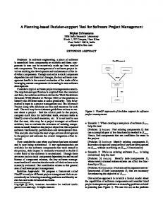
Assembly planning is a very complex problem when it is viewed in the context of robots and other automated devices programming (Figure 1). Assembly planning defines the assembly operations and their sequence, the fixture design, the tool selection and the workspace layout, satisfying a set of technical and economical requirements. This process produces the assembly sequence, which is executed by an automated device. In order to do this, it is necessary to plan the grasp points selection and the grasping of each module, the path planning from the module initial position to the destination position and the execution of the fine motion to insert the module, making a suitable use of the device sensors during all these operations [14].
Assembly Planning • • • •
Assembly Operations. Fixture Design. Tool Selection. Workspace Layout
a)
Assembly Sequence
High Level Programming • • • •
Grasp Planning. Path Planning. Fine-Motion Planning. Sensory Planning.
b) Figure 2. a) Cones connector, b) platform artificial vision system.
Automated devices commands
2.1 Assembly sequence planning Assembly sequence planning searches the order and spatial direction in which the insertion of each module should be done. This sequence should satisfy the following types of restrictions and criteria: a)geometrical restrictions, b)physical restrictions, and c)assembly process related restrictions and criteria. Geometrical restrictions are those related to the collision between parts in the assembly process. Physical restrictions are those related to the unwanted changes due to gravity, unwanted motion, etc. (these restrictions are also defined as the assembly stability). The assembly process
Figure 1. Assembly planning in the context of automated devices programming. A key concept to obtain a successful automated assembly system is the integration of the planning process with the design and execution processes [2]. This concept has been applied in FutureHome. On one hand, specially developed assembly connectors has been added to the prefabricated modules to allow a bigger tolerance of robotized crane movements and to help the insertion of modules (Figure 2-a). On the other hand, the crane has been provided with a
2
assembly sequence. In addition, a special attribute, grouping, is provided to take into account custom planning criteria. This attribute has the biggest priority allowing the division of a given work in smaller tasks. The sorting time for a building containing 70 modules using this method is instantaneous. The tool is also provided with a manual sorting feature to face unexpected events during the execution process.
(available fixtures, tools and workspace) can be specified to the assembly sequence planer by means of a set of restrictions and criteria. A criterion, unlike a restriction, is a measure for evaluation. This kind of restrictions and criteria allow the generation of different sequences and the selection of the most suitable one. Assembly sequences search is a NP-complete computational problem [8], that is the time needed to determine the optimal assembly sequence grows exponentially with the number of parts. Due to this complexity most of the existing planners are interactive systems, which generate two-handed monotone assembly sequences in reverse, starting from the more highly constrained, full assembly state [15]. Some of the most known assembly planners are: DFA 8.0 and DFA/Pro, this is a very useful advisory system, widely used in the industry, and Archimedes 4.0 an ACIS enabled automatic planner with an interactive user interface and a library of restrictions, that allows assembly planning in a very pragmatic way. The authors of the system have reported the assembly planning of a Hughes Aircraft air-to-air missile guidance section with 472 parts in 22 minutes [6].
2.2 Motion planning Motion planning defines the spatial trajectories of the modules during the assembly and the automated device or robot commands needed for their execution. Motion planning is defined as follows: given the initial and the final configuration of the module, find a joining path that avoids collision with the obstacles. There are many techniques and algorithms for motion planning, but they are generally classified in three groups: roadmaps, cells decomposition and potential fields [10]. Though motion planning has been solved exactly [3], the obtained algorithms are slow and complex. The complexity of the motion planning problem grows exponentially with the number of degree of freedom (DOF) of the robot and in a polynomial way with the number of obstacles. Nevertheless, there are many problems in practice that are not really complex and that can be solved exactly or in a approximated way. For robots with four or less DOF of freedom it is possible to solve motion planning problem, using roadmaps or approximated cells techniques in C-space, within a few seconds or a few minutes, depending upon problem complexity [7]. Motion planning for robots with more than four DOF is an active research area. Some of the outstanding motion planners in this area are: the Probabilistic Roadmap Planner (PRM) – this planner generates a roadmap based on random, but properly selected, collision-free configuration nodes, and uses this roadmap to find paths [9], SANDROS – a hierarchical, multi-resolution dynamic-graph search planner [4] and AMROSE – a multi-agents, artificial potential based system applied to off-line high level programming of welding applications [12].
In the FutureHome project, pre-fabricated modules are vertically assembled using a cones connector system (Figure 2-a). This system allows the auto-centring of the modules during the insertion, as well as a bigger tolerance in the precision of the crane movements. The assembly by means of cones connectors can be considered a stack assembly (i. e., one in which all the assembling motions occur in a single direction, usually up-and-down.). In a construction work, assembly is always performed on a structural basis. This leads to sort assembly sequence inserting first those modules of bigger “structurality” i.e. modules that support another modules. This sort according “structurality” is performed on levels, and inside the same level, it is performed on coordinates. Therefore, if these attributes: “structurality”, level and co-ordinates of the insertion point, are assigned to each module, then it is only needed to sort the modules according to these attributes to obtain the
3
Free plane Floor 2 Level
+ 0,5 m
Assembly Plane
+1 floor + 0,5 m
Floor 1 Level
Figure 3. Working planes of the AUTMOD3 motion planning tool. In order to reduce the motion planning complexity, AUTMOD3 motion planner basically works on two planes. These planes are called assembly plane and free plane (Figure 3). Assembly plane is defined at 0,5 m of height with respect to the current assembled level. Free plane is defined at 0,5 m of height with respect to the next (higher) level than the currently being assembled. Initially, the planner looks for a path free of collisions in the assembly plane using a variant of the tangent graph algorithm [4]. If this path does not exist, its distance is very large or the execution time of the algorithm is large, the planner rises the module to the free plane, carries it directly over the insertion point, lowers the module and proceeds to the insertion. In addition, the tool is provided with a manual planning function allowing the modification of the obtained trajectories or the generation of other types of paths. This method trades-off
optimality versus complexity producing a simple algorithm.
a)
b)
Grasping operations are automatically performed by means of the electromagnets and the artificial vision system installed in the crane platform, while insertion operations are also automatically realised using the cones connectors and the crane platform artificial vision system. 3. APPLICATION TO THE FUTUREHOME ROBOTIZED CRANE The AUTMOD3 assembly planning tool is integrated in the AutoCAD environment. It is accessible from the menu bar and communicates with the design tool through the AutoCAD database.
Figure 4. a) Calling the AUTMOD3 assembly planner, b) visualising modules assembly properties.
4
c)
d)
e)
f)
Figure 4 (cont.). c) Sorting modules according to their properties, d) visualising the assembly, e) automatic motion planning: a trajectory for the assembly of the Facade 1 module, f) visualising robotized crane commands. modular construction of the designed building in the demonstrator (Figure 6).
The planning tool is presented as a single dialogue box in which the planner can chose the needed functionality: a) general manipulation of sequences (creating, destroying and selecting sequences), b) visualisation and manipulation of modules assembly properties, d) automatic and manual sorting according to these properties to obtain an assembly sequence, d) visualising the assembly, e) motion planning for each module in the sequence and f) exporting the robotized cranes commands (see Figure 4). Once the assembly sequence and the robotized crane commands has been obtained, the assembly can be simulated in the AUTMOD3 simulation tool or the commands can be sent to the robotized crane for their execution. This crane is used to assembly modules in a demonstrator with 1:3 scale modules (see Figure 5). The AUTMOD3 software environment jointly with the robotized crane control system permits the automatic
4. CONCLUSIONS The AUTMOD3 planner, dedicated to obtain the assembly sequence and the motion planning for the automatic assembly of modules, has been presented. The key concepts that make application of this automatic planner feasible are exposed: a great integration of the assembly planning with the real assembly process has been achieved, and a suitable strategy of movement for modular assembly has been defined. This methodology allows to avoid algorithm complexity obtaining a fast and practical procedure. Finally, the automatic assembly of the modules employing AUTMOD3 tool and the robotized crane has been shown.
5
[6] Halperin, D., Latombe, J. C. and Wilson R.H., “A General Framework for Assembly Planning: The Motion Space Approach.” Algorithmica, 26(3-4), pp. 577-601, 2000. [7] Gupta, K., “Overview and State of the Art”, Practical Motion Planning in Robotics: Current Approaches and Future Directions, Eds. Gupta, K. and del Pobil, P., John Wiley, pp. 1-8, 1998. [8] Kavraki, L., Latombe, J-C. and Wilson R.H., “On the complexity of assembly partitioning”, Information Processing Letters, 48(5), pp. 229235, 1993.
Figure 5. Carlos III University of Madrid robotized crane.
[9] Kavraki, L., Latombe, J.-C., Motwani, R., and Raghavan, P., “Randomized Query Processing in Robot Path Planning”, Journal of Computer and System Sciences, 57(1), pp. 5060, 1998. [10] Latombe, J. C., Robot Motion Planning, Kluwer Academic Publishers, 1991. [11] Liu, Y-H. and Arimoto S., “Computation of the Tangent Graph of Polygonal Obstacles by Moving-Line Processing”, IEEE Trans. on Rob. and Automation, 10(6), pp. 823-830, 1994.
Figure 6. Robotized crane assembling a module. 5. REFERENCES
[12] Overgaard, L., Larsen, R. and Jacobsen, N., “Industrial Applications of the AMROSE Motion Planner”, Practical Motion Planning in Robotics: Current Approaches and Future Directions, Eds. Gupta, K. and del Pobil, P., John Wiley, pp. 155-183, 1998.
[1] Tracey, A., Child, T., Aouad, G., Brandon, P. and Rezgui Y., “Developing integrated applications for construction: the OSCON Approach”, I International Conference on Computing and Information technology for AEC, Singapore, July, pp. 361-368, 1996.
[13] Peñín, L.F., Balaguer, C., Pastor, J.M., Rodríguez, F.J. and Barrientos, A., “Robotized Spraying of Prefabricated Panels”, IEEE Robotics and Automation Magazine, September, 18-29, 1998.
[2] Boothroyd, G. and Alting, L., “Design for assembly and disassembly”, Annals CIRP, 41(2), pp. 625-636, 1992. [3] Canny, J., The complexity of Robot Motion planning, MIT press, 1998.
[14] Wolter, J.D., On the automatic generation of plans for mechanical assembly, PhD Thesis, The University of Michigan, 1988.
[4] Chen, P.C. and Hwang, Y. K., “SANDROS: A Dynamic Graph Search Algorithm for motion planning”, IEEE Transactions on Robotics and Automation, 14(3), pp. 390-403, 1998.
[15] Zha, X.F., Lin, S.Y.E. and Fok, S.C., "Integrated Intelligent Design and Assembly Planning: A survey", Int. J. Adv. Manuf. Technol. 14, pp. 664-685, 1998.
[5] Diez, R., Abderrahim, M., Padrón, V.M., Celorrio, L., Pastor, J.M. and Balaguer, C. “AUTMOD3: An automatic 3D moularization system”, 17th ISARC, Taipei, (Taiwan), pp. 1033-1038, 2000.
6. ACKNOWLEDGEMENT This work has been supported by the EU FutureHome project (BRITE nº ER4-29671)
6
7