CONTROL OF A BIOMIMETIC “SOFT-ACTUATED” LOWER BODY 10DOF EXOSKELETON Nelson R. S. Costa1, Darwin G. Caldwell Centre for Robotics and Automation School of Computing, Science and Engineering - University of Salford, M5 4WT, UK Phone: +441612954010 - FAX +441612955145 - E-mail:
[email protected]
Abstract: Currently many patients with brain/spinal cord/sport injuries or stroke, are confined to wheelchairs which results in many secondary conditions. Locomotor training attempts to encourage the patient to undertake walking exercises but the physical effort is such that there is poor compliance, as it requires a highly intensive and task-specific therapy approach. Powered Locomotor trainers aim to promote motor recovery, reducing this effort to a tolerable level encouraging higher levels of exercise, improved secondary health care and to obtain a better understanding of human motor walking gait. This paper will address the development and control of a lower limb exoskeleton for active assistive walking. Copyright © 2006 IFAC Keywords: Exoskeleton, walking, control, rehabilitation, pneumatic muscle actuators, muscle
1. INTRODUCTION Advanced Robotics includes many fields and areas, like rehabilitation or prosthetics that emerged during the 1990s for human performance augmentation and assistive walking training, representing nowadays one of the most interesting, challenging and complex areas of research. Currently many patients who suffer from stroke, brain or sports injuries and spinal damage are confined to wheelchairs. This can cause a variety of secondary problems including; contractures, pressure sores, bowl infections, osteoporosis, and kidney infections. In addition the sedentary lifestyle in many cases causes the patient to become dependant on a carer (NHS-UK, 2002). Locomotor training following neurological injury has been shown by many studies to have therapeutic benefits, but treatment relies on physiotherapy procedures which by their very nature are extremely labour intensive requiring high levels of one to one attention from highly skilled medical personnel. At the same time these training and rehabiliation activities place extreme physical strain on the patient and the effort required by the patient leads to low levels of compliance. All this must be achieved in an environment in which there is a global shortage of staff with appropriate training (NHS Audit Commission, 2002) One alternative to manual locomotor training is the use of powered limb orthoses to provide mechanical assistance during walking. Two approaches to the development of powered locomotor training have been evolved. i). Functional Electrical Stimulation Hybrid orthoses have been linked to functional electrical stimulation (F.E.S) in an approach where the muscles of 1
the patient’s leg are externally stimulated to generate the motions with support provided by an orthosis (Muccio et al., 1989). Steady progress is being made using this technique but unfortunately, there are unwanted side effects. In particular there are issues with skin irritation (which can be addressed) and fatigue since the technique can require more than 9 times the energy consumption of “normal” walking due to over stimulation of anatomical muscle groups and the subsequent unsuitably high torque production (Clinkingbeard et al., 1964). The high energy/effort required by the patients in all the current rehabilitation options means that compliance is low. ii). Externally Powered Orthosis. In this approach, the orthosis is externally powered using electrical drives. A number of recent devices have been developed with this approach which is designed primarily for hospital based rehabilitation. Lokomat is a 4 dof per leg treadmill based system while the Fraunhofer walker provides 3 dof per leg in a crank slider motion with rotation for the ankle (Van der Loos, 2004). These externally powered devices have achieved some success but the nature of the interaction between the patient and the user is critical and although there are a variety of safety features within the designs of each of the systems there are safety and dependability concerns. This should extend beyond monitoring systems and should form part of the design philosophy. In particular, where humans and mechanical systems operate in close proximity there is a need to provide drive systems that combine the positive attributes of conventional actuator design with a ‘softer’, safer “biological” and natural muscle comparable interaction capacity.
Finantial support granted by the Fundação para a Ciência e a Tecnologia (FCT) under the “Programa Operacional Ciência, Tecnologia, Inovação” and the “Programa Operational Sociedade de Informação” is gratefully acknowledged.
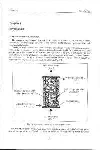
Spinal Column Support & Hip Abd/Add pMAs Pelvic Girdle Hip
Knee
Thigh side bars & Hip/ Knee Flex/Ext pMAs muscles Rear thigh
produced in a range of lengths and diameters and are simple to manufacture; have an extremely high power/weight ratio; contract by 30-35% of their dilated length, depending upon construction; ‘Soft’ construction and finite maximum contraction making it safe for human-machine interaction; Muscles can be controlled to a displacement accuracy of 1% and can have a bandwidth of 5Hz when operating antagonistically and if compared with natural muscle provide up to 10 times more force for a similar cross-sectional area. (Caldwell et al., 1995)
Ankle Plantar Flex Dorsiflexion pMAs Rear lower
Ankle Fig.1. Author Wearing the Lower Body Exoskeleton Knowing that the one, who wants to relearn walking, has to walk, this paper presents the implemented main control modes for task-specific therapy based approach. This exoskeleton intelligent assistive training device shows how the “soft interaction” but strong and lightweight pMAs can emulate much of the action of natural muscle and integrated into a mechanical/kinematic structure. The paper will finally draw conclusions based on this work and suggest a path for the future.
2. PMAS ACTUATORS/HUMAN MUSCLE Actuators and actuation systems are essential critical parts to all robotic structures providing the forces, torques and mechanical motions needed to move the joints, limbs or body. Their performance is usually characterized by parameters such as power (particularly power/weight and power/volume ratios), strength, response rate, physical size, cost, speed of motion, reliability, controllability and compliance. Within humans and by replication in this exoskeleton all joint motion is achieved by producing appropriate antagonistic torques since the pMAs is only capable of generating a pulling force when it contracts axially during the expansion constrained by the outer layer. In the human this is transmitted through tendons to the joint lever while in here the power is distributed through cables and pulleys driven by pMAs. The original concept was developed by McKibben for prosthetic applications in the 1950’s but it fell into disuse because of the complexity of control, the need for a compressed air supply and the relative ease of use of electrically powered prosthesis controlled by myoelectric signals has lead to their replacement (Schulte, 1961). These actuators have characteristics that are well suited to both robot motion systems and particularly human robot interaction. On the other hand, the pneumatic Muscle Actuator has a number of important desirable characteristics: muscles can be
Fig.2. Torque transmission using antagonistic pair This figure represents the typical joint control scheme using two pMAs in antagonistic scheme, each working in opposition to control the position of the joint and thus, effectively providing constraints in rotation. The detailed construction, operation, analysis and performance comparison to the Natural Muscle can be found in (Caldwell et. al., 1993, 1995 and Chou et al, 1996). Although the underlying mechanisms of operation are very different, the pMA can in most instances equal the natural behaviours of the muscle while possessing excellent ‘engineering’ power, endurance and robustness. Having noted that pMA has the inherent capacity to modulate compliance/impedance and potential to produce a biologically inspired actuator, combining many, if not all the best features of natural and technological science so far, the next stage was how to incorporate these actuators into a lower body exoskeleton prototype.
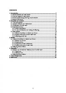
3. MECHANICAL STRUCTURE DESIGN The mechanical structure used to form an exoskeleton to assist those with paralysis or muscle wastage consists of a of 10 Degrees of Freedom mechanism, with only 8DoF currently controlled, corresponding to the fundamental natural motion and range of the human legs from the hip to the ankle but excluding the less significant movements. The hip structure has 3 DoF in total (flexion/extension, abduction-adduction and lateral-medial rotation, but the last one being no co-axial was not controlled), 1 DoF at the knee permitting flexion/extension of the lower leg and 1 DoF at ankle (dorsiflexion /plantar flexion).
8.1Kg
3.6Kg
1.3Kg
Fig.3. Average mass in Kg and centre of gravity of limbs and joint coordinates conventions The legs structure is constructed primarily from aluminium, with joint sections fabricated in steel, using precision mechanics. The leg is mounted onto a moulded lower body brace which is light, low cost and comfortable while providing a stable platform. The leg and the brace were constructed for use by a NASA 'typical average adult' USAF personnel (figure 3 left), without major changes to the set-up, although leg link length changes can easily be adjusted up-to ±80mm, if necessary. The total weight of the exoskeleton (not optimized) consisting of the both legs and rigid spine is currently less than 12kg fully assembled. As with electrical systems it must be recognised that currently this mass does not include the power source. Computational requirements are not severe and microcontroller operation is possible. The compact actuator structure allows for integration as close as possible to their respective powered joints. The ankle actuators (two actuators) and the lower leg flexion/extension actuator (two actuators) are mounted on the side. The knee actuators (two actuators) and the leg hip flexion/extension (two actuators) are mounted on the thigh side while the hip abduction/adduction actuators (four actuators if we include the internal/external rotation) are mounted on the body brace pack behind the operator’s back. Each antagonistic scheme includes a high linearity potentiometer for position sensing and an integral pulley strain gauge torque sensor. The muscles used in this project have a diameter of 3cm, with an ‘at rest’ length of 35cm and 60cm. Ankle joint insertion-end Leg adjustable side Ankle joint
Hip joint origin-end Knee joint insertion-end Pelvic Girdle Ankle joint origin-end Thigh adjustable side bars Knee joint
Fig.5. Knee joint with Thigh and Leg side bars and pMAs attachment points Hip joints
Hip Flex/Ext insertion-end Knee origin-end
Thigh side bars
Fig.6. Pelvic Girdle, Hip joints, Thigh side bars and pMAs attachment points The performance specification for the joints of the human leg are shown in table 2 (Luttgens and Hamilton, 1997), together with the maximum joint torque and range of motion, that is mechanically adjusted to the user’s comfortable limits. JOINT / SEGMENT Movement Hip Flexion/Extension Adduction/abduction Internal Rotation External Rotation Knee Flexion/Extension Ankle Plantar Flexion/Dorsiflect
Human Isometric Strength/Range
Achieved Joint Torque Range
110Nm 120°/20° 125Nm 45°/30° 35°-45° 45°-50°
60Nm 135°/45° 65Nm 135°/135° 110° 110°
72.5Nm 140°
60Nm 140°
19.8Nm 50°/30°
60Nm 105°/45°
Table 1 – Performance and ranges of motion of “normal” human versus pMA powered exoskeleton device Shoe attachment points
Fig.4. Ankle joint and Leg adjustable side bars
4. PMAS MODEL AND CONTROL In figure 2, the pMAs are modelled as pure springs with variable stiffness Kd1, Kd2. For an angle θ the forces developed by the actuators are given by (Caldwell et al., 1995; Tsagarakis et al., 2003 and Davis et al., 2003):
F1 = K d1 ⋅ (a + r ⋅ θ ) and F2 = K d 2 ⋅ (a − r ⋅ θ ) (1)
To achieve the maximum controllable range of motion, a has been set equal to the half of the maximum displacement. At any time the torque developed is given by: (2) T = ( F2 − F1 ) ⋅ r
The command pressure for the muscles at each cycle are given by: P1 =
Pmax − ΔP 2
P2 =
Pmax + ΔP (3) 2
Where ΔP is computed using a PID control law
ΔP = K p1 ⋅ e +
1 e + Td ⋅ e& and e = τ d − τ s (4) Ti ∫
is the joint torque error, Pmax is the maximum pressure within the pneumatic muscle actuators and
τ d is set to be
equal to the optimal state feedback. Therefore the torque developed by the muscle becomes:
⎡c1l 2 c 2 + l1c1 + c1c2 l3 c3 − s1l3 s3 + c1c2 c3l 4 c4 − s1 s3l 4 c4 − c1c 2 s3l 4 s 4 − s1c3l 4 s 4 ⎤ p knee (l p ) = ⎢⎢ s1l 2 c2 + l1 s1 + s1c 2 l 3 c3 + c1l3 s3 + s1c 2 c3l 4 c4 + c1 s3l 4 c 4 − s1c2 s3l 4 s 4 + c1c3l 4 s 4 ⎥⎥ l 2 s 2 + s 2 l 3 c3 + s 2 c3 l 4 c 4 − s 2 s 3 l 4 s 4 ⎣⎢ ⎦⎥
⎡c1l 2 c 2 + l1c1 + c1c 2 l3 c3 − s1l 3 s3 + c1c 2 c3 l 4 c 4 − s1 s3l 4 c 4 − c1c 2 s3 l 4 s 4 − s1c3l 4 s 4 ⎤ p foot (l p ) = ⎢⎢ s1l 2 c 2 + l1 s1 + s1c 2 l 3 c3 + c1l 3 s3 + s1c 2 c3l 4 c 4 + c1 s3l 4 c 4 − s1c 2 s3l 4 s 4 + c1c3 l 4 s 4 ⎥⎥ ⎢⎣ ⎥⎦ l 2 s 2 + s 2 l 3 c3 + s 2 c3 l 4 c 4 − s 2 s 3 l 4 s 4 ⎡(c1c 2 c3 c 4 − s1 s3 c 4 − c1c 2 s3 s 4 − s1c3 s 4 )l5 c5 + ( s1 s3 s 4 − c1c 2 c3 s 4 − c1c 2 s3 c 4 − s1c3 c 4 )l5 s5 ⎤ + ⎢⎢( s1c 2 c3 c 4 + c1 s3 c 4 − s1c 2 s3 s 4 + c1c3 s 4 )l 5 c5 + (c1c3 c 4 − s1c 2 c3 s 4 − s1c 2 s3 c 4 − c1 s3 s 4 )l5 s5 ⎥⎥ ( s 2 c3 c 4 − s 2 s3 s 4 )l5 c5 − ( s 2 c3 s 4 + s 2 s3 c 4 )l5 s5 ⎣⎢ ⎦⎥
In static consideration the same transformation is used to relate the external force and moments applying at the end-effector to the torques at the joints. These previous statements can be algebraically expressed using the following equations (Tsagarakis et al., 2003).
T = 2 ⋅ r ⋅ a ⋅ K p ⋅ ΔP − 2 ⋅ r 2 ⋅ ( K p ⋅ Pmax + K e ) ⋅ θ (5) The joint torque data is provided from the integrated strain gauge joint torque sensor present at each joint.
5. EXOSKELETON 3D MODEL Kinematics is the modeling of the spatial relation-ships between positions, velocities and accelerations of the structure links of a manipulator, described here in terms the standard Denavit-Hartenberg (DH) parameters. Figure 7 shows the assignment with link parameters of coordi-nate frames to mechanical links in zero position.
⎡v ⎤ J ⋅θ& = ⎢ ⎥ , ⎣ω ⎦
⎡F ⎤ JT ⎢ ⎥ =τ ⎣M ⎦
Considering a generic exoskeleton legs with n degrees of freedom, as previously described J is the exoskeleton Jacobian, ν , ω are the 3x1 vectors of translation and rotational velocity, with F , M being the 3x1 vectors that describe the forces and moments acting at one specified point on the exoskeleton structure, θ& is nx1 vector of joint rates and τ is the nx1 vector of joint torques/forces. Thus, using equation the Jacobian J knee , J ankle and
J foot can be formulated. ⎡− K y 0 ⎢ K ⎢ x0 ⎢ 0 J 0 knee= ⎢ ⎢ 0 ⎢ 0 ⎢ ⎣⎢ 1
0
Fig.7. Exoskeleton model with kinematic parameters With the DH formultation, it’s now possible to calculate the absolute position of any point of interest in any link of the exoskeleton legs. Final homogeneous transforms are: ⎡c1l 2 c 2 + l1c1 + c1c 2 l3 c3 − s1l3 s3 ⎤ p hip (l p ) = ⎢⎢ s1l 2 c 2 + l1 s1 + s1c 2 l3 c3 + c1l3 s3 ⎥⎥ ⎢⎣ ⎥⎦ l 2 s 2 + s 2 l3 c3
J ankle
⎡ − Ay 0 ⎢ A ⎢ x0 ⎢ 0 =⎢ ⎢ 0 ⎢ 0 ⎢ ⎣⎢ 1
− c1 K z1 − s1 K z1 s1 K y1 + c1 K x1 s1 − c1 0
s1 s2 K z 2 − c2 K y 2 ⎤ c2 K x 2 + c1 s2 K z 2 ⎥⎥ − c1 s2 K y 2 − s1 s2 K x 2 ⎥ ⎥ − c1 s2 ⎥ ⎥ s1 s2 ⎥ c2 ⎦⎥
− c1 Az1
s1 s2 Az 2 − c2 Ay 2
− s1 Az1 s1 Ay1 + c1 Ax1
c2 Ax 2 + c1 s 2 Az 2 − c1 s 2 Ay 2 − s1 s2 Ax 2
s1
− c1 s 2
− c1 0
s1 s2 c2
s1 s2 Az 3 − c2 Ay 3 ⎤ c2 Ax 3 + c1 s2 Az 3 ⎥⎥ − c1 s 2 Ay 3 − s1 s 2 Ax 3 ⎥ ⎥ − c1 s2 ⎥ ⎥ s1 s 2 ⎥ c2 ⎦⎥
The Jacobian formulated here can now be used to calculate the necessary hip, knee and ankle joint torques in order to “reflect “ a specified external momentum or load generated at any single point between hip and knee, ankle or foot using the following equation:
⎡τ 1 ⎤ ⎢τ ⎥ = J T ⎢ 2 ⎥ 0 knee,ankleorfoot ⎢⎣τ 3 ⎥⎦
⎡ F⎤ ⋅⎢ 0 ⎥ ⎣0M⎦
As previously noted, special care must be taken in order to ensure that the vector of the external load (both force and moment) has been expressed with respect to the same reference frame as the Jacobian for the validity of computed values. For the exoskeleton legs case, this reference frame is the base frame (frame 0). Many control schemes require the inverse of the Jacobian. At a kinematic singularity the Jacobian becomes singular, and such simple control techniques will fail. There is a constraint in knee joint, such that it
can move only forward, which solves the singularity problem.
Driver & solenoid
5.1. Manipulator rigid-body dynamics Robot dynamics is concerned with the equations of motion, the way in which the robot moves in response to torques applied by the actuators, or external forces. An impedance control scheme was employed for the overall rehabilitation/training exoskeletal system. The following equations of motion describe the dynamic behaviour of the exoskeleton for an n-axis are given below. (The impact of the swing leg is assumed to be perfectly inelastic while ensuring that no slippage occurs. Moreover, a physical realisability of motion implies that the foot can’t push on the ground. The dynamic equations for the five link biped during a single-support phase are && + C(q, q&) + G(q) = τ of the form: M (q) ⋅ q
M ( q ) ⋅ q&& + C ( q , q& ) + F ( q& ) + G ( q ) + J T ⋅ F R = τ
jo int
Where:
q
Is the n×1 vector of generalized joint coordinates describing the pose of the manipulator or the joint variable n-vector Is the vector of joint velocities
q& q&&
Is the vector of joint accelerations
M
Is the n×n symmetric joint-space inertia matrix, or robot inertia tensor matrix describes Coriolis and centripetal torques/effects –
C
Centripetal torques are proportional to Coriolis torques are proportional to F
G Q
τ jo int FR
JT
q& i2 ,
while the
q& i q& j
Interface Fig.8 Hub with interface keyboard & microcontroller board with valve drivers Each antagonistic pair is controlled by three PID controllers (two low-level for pressure and one higherlevel for position/torque) on all the joints, figure 9. As the muscles operate in pairs the value provided by the controllers is added to one of the muscles and subtracted from its antagonist counterpart. The MCUs are connected through a serial data bus to central controller or HUB. The hub consist one microcontroller Atmel ATMEGA128 with 2functions. Firstly the hub coordinates all valve control units and feed them with self-generated data which are based on the exoskeleton operating mode. Secondly the hub should be used only as the interface between PC and the valve controllers. In this case all inputs are generated by the PC. Communication between the hub and PC is completely wireless making use of new BlueTooth technology. PC based interface and data operation software was developed in Matlab simulink using real time functions.
Is the friction vector that describes viscous and Coulomb friction and is not generally considered part of rigid-body dynamics Is the gravitational loading n×1 vector torques Is the vector of generalized forces associated with the generalized coordinates q is the joint n×1 vector of the generalized actuated torques is the force that the leg generates at the end-tip is the transpose Jacobian of the manipulator
The above equation can be used to describe the interaction between human user and the exoskeleton. Fig.9. 3 Level PID Joint Torque Control scheme
6. SYSTEM CONTROLLE & INTERFACE Eight port 2/2 pneumatically Matrix valves (weighing less than 300g with 45mm x 55mm x 55mm) are used to control the air flow are used within this design and mounted at the base of the spine. These valves can be driven and controlled at up to 200Hz using a PWM signal (Costa et al., 2001). This provides rapid, smooth motion. Development and adjustment of a controller and details of the design can be found in. Closed loop controller is achieved pulsing the valves along with data collection from the position, pressure or torque sensors, to an I/O, ADC dedicated microcontrollers outputs (Atmel ATMEGA8 - Fig.8. The external PC is only required to store data collected under normal conditions. Every valve microcontroller board consists of two microcontrollers, which allows to board handle two muscle pairs/joints. Microcontroller HUB
7. EXPERIMENTAL TESTING RESULTS A chirp signal (Fig.10 A B) with different amplitudes and frequencies was used to evaluate the closed loop frequency response of each joint. The purpose of these tests was to draw conclusions on the feasibility of using the exoskeleton for physiotherapy, rehabilitation and training. For each joint the amplitude was set to ±12º and ±25º with frequency range swiping from 0..4Hz in 100ms steps over a specified period of t=180s. The frequency was reduced to 1.5Hz on the knee/hip (t=90s) and when links were loaded with the human limbs normal weight (as shown in Fig.3), it was reduced to 1Hz at the hip.
1
-30 -40 -50 -60
0
-5
A 100
B
200
300 400 Time (sec x 100)
500
600
0.6
-500
0.5
1350
1400
1450 Time (sec x 100)
1500
0.4
C
-2
-1
10
0
10 10 Frequency (Hz), Unloaded 12
-1500 -3 10
1
10
10
Figure 11, AD-unloaded & BE-loaded with human normal weight, shows the right ankle TFE to a 180sec cycle; ±12º & ±25º reference sinusoidal chirp signal with frequencies up to 4Hz and stiffness 100, 160 and 200, respectively. Fig.12 AD & BC shows same test sequence applied to the knee, and 13 & 14 the two controlled DoF at the hip. Phase (deg) is shown on picture right side. -2
-4
-4
-6
-6
0 -20
-2
10
-1
0
10 10 Frequency (Hz), Loaded/Unloaded 12
-400
1
10
2
10
-20
-30
-40
D, ±25ºunloaded
-50
-60 -3 10
-2
10
-1
0
10 10 Frequency (Hz), Unloaded 25
-600 -3 10
10
-2
2
10
0
1
10
-400
-30
-40
E, ±25ºloaded 10
-2
-1
0
10 10 Frequency (Hz), Loaded/Unloaded 25
-2
10
0
-20
-70 -3 10
C, Phase
-1500 -3 10
10
-200
-60
1
-1
10 10 Frequency (Hz), Loaded/Unloaded 25
-10
-50
10
-1000
B, ±12ºloaded
0
-10
Magnitude Gain (dB)
Figure 10A exhibits the antagonistic muscle efforts and B illustrates how well the implemented closed loop control scheme is able to track the reference and compensate for the actuator response shortcomings. The Transfer Function Estimate (TFE) was computed by averaging several cross powered spectral densities and using a suitable Kaiser window to reduce the impact of leakage, with the overlapping sample points from section to section half of the defined for the Kaiser averaging window. In parallel, to have an estimate on the precision how good the TFE was, a coherence function was used. This coherence is a function of frequency with values between 0 and 1, that indicate how well the input corresponds to the output at each frequency (Fig.10C) were we can see that inside the excitation frequencies the TFE is very accurate (over 0.6). These were implemented in Matlab (considering 30Hz sampling frequency), to all joints under different testing conditions: amplitudes, time, frequency range and stiffness.
A, ±12ºunloaded
0
Fig.10 Joint muscle efforts, Position control & Coherence
-2
0
-500
-1000
0.3
0.1 -3 10
1550
0
-200
0.2
-10
500
200
0.7
Phase (deg)
-20
1000
0
Phase (deg)
-10
600
400
0.8
Phase (deg)
Magnitude Squared Coherence Estimate
5
0
Joint Angle (deg)
Pressure (bar)
10
500
0.9
10
20
Magnitude Gain (dB)
30
10
1
10
2
10
-800
-1200
1
0
-600
-1000
10
-1
10 10 Frequency (Hz), Loaded/Unloaded 12
F, Phase
-1400 -3 10
-2
10
-1
0
10 10 Frequency (Hz), Loaded/Unloaded 25
10
1
2
10
Fig.13. Hip TFE unloaded at left and loaded at center. Experimental results revealed on previous figures shows a phase lag which follows a characteristic profile typical of a 1st order system. Nyquist frequency is half of the sampling frequency, as showed on all X-axis. To avoid affecting and disturbing the results all DC sensor levels were removed with a “dtrend” Matlab function, so they are around 0 in average. The smallest frequency we can measure depends on how good the excitation signals were and how the tests were carried out. The current performance is less than would be acceptable for an full power knee prosthetic limb, however, ongoing prototype updates and research suggests that this can be increased by several hundred percent and this will form part of future developments, some of them already being implemented at present for this system. Overall response, muscle efforts, ability to handle load disturbances, human gait system-tracking/guiding capabilities achieved with a healthy individual (to ensure stability and safety) revealed that it may be successfully used for some medical conditions involving degenerative muscle wasting diseases/weak lower limb muscles or reduced coordination of human motor control.
-40
-12 -14
-18 -20 -3 10
A, ±12ºunloaded -2
10
-2
-1
0
10 10 Frequency (Hz)
2
10
-12 -14 -16
D, ±25ºunloaded
B, ±12ºloaded -2
10
-1
0
10 10 Frequency (Hz)
-180 1
10
2
10
-4
-20
-6
-40
-2
10
-1
0
10 10 Frequency (Hz)
10
1
10
2
-14
-2
-1
0
10 10 Frequency (Hz), Loaded/Unloaded 12
1
10
2
10
-80 -100 -120 -140
-16
-22 -3 10
10
-60
-12
-20
C, Phase
-200 -3 10 0
-10
-18
8. CONCLUSIONS AND FUTURE WORK
-120
-160
-8 Magnitude Gain (dB)
-8 Magnitude Gain (dB)
-20 -3 10
-80 -100
-140
-2
-6
-22 -3 10
-14
-18
1
10
-4
-20
-12
-16
-10
-18
-10
Phase (deg)
-16
-8
Phase (deg)
Magnitude Gain (dB)
Magnitude Gain (dB)
-60 -8 -10
E, ±25loaded 10
-2
-1
10 10 Frequency (Hz)
0
-160 -180 1
10
10
F, Phase
-200 -3 10
-2
10
-1
0
10 10 Frequency (Hz), Loaded/Unloaded 25
1
10
10
Fig.11. Ankle TFE unloaded at left and loaded at center. 10
500
0 -5
0
-10
0
-20
-30
-15
Phase (deg)
Magnitude Gain (dB)
Magnitude Gain (dB)
-10
-20 -25 -30
-40
-50
-60 -3 10
A, ±12ºunloaded -2
10
0
-1
0
10 10 Frequency (Hz), Unloaded 12
-35 -40
1
10
2
10
-500
-45 -3 10
-1000
B, ±12ºloaded 10
-2
0
-1
0
10 10 Frequency (Hz), Loaded 12
1
10
C, Phase
-1500 -3 10
10
-2
10
600
-1
0
10 10 Frequency (Hz), Loaded/Unloaded 12
1
2
10
10
-5
-10
400
-30
-40
-50
-60 -3 10
D, ±25ºunloaded -2
10
-1
0
10 10 Frequency (Hz), Unloaded 25
-20 -25
-40
2
10
-45 -3 10
0
-200
-30 -35
1
10
200
-15
Phase (deg)
Magnitude Gain (dB)
Magnitude Gain (dB)
-10
-20
E, ±25ºloaded 10
-2
-1
0
10 10 Frequency (Hz), Loaded 25
An inherent safe lower body pneumatically powered exoskeleton was presented and the system effectiveness presented. This is currently being assessed when acting as a power assistive device for rehabilitation, prosthetics and training with different task-specific therapy based approach aimed to guide or assist the human gait. This is achieved either by augmenting, constraining or even stopping the users movement, and may be successfully used for some medical conditions as rehabilitation of stroke, traumatic brain/spinal cord/sport injured patients that suffering from degenerative muscle wasting diseases/weak lower limb muscles.
-400
1
10
10
F, Phase
-600 -3 10
-2
10
-1
0
10 10 Frequency (Hz), Loaded/Unloaded 25
1
10
10
Fig.12. Knee TFE unloaded at left and loaded at center.
In fact, the ‘soft’ pMAs actuator that macroscopically has many characteristics similar to natural muscle, while still retaining beneficial attributes may provide a valuable insight into this “biological implementation” and development of new range of powered assistive devices. Future work will investigate the use of this structure in active and passive power assistive modes. Key developments will include: Enhanced power outputs from the actuators to equal the power of human leg muscles; integration into a full body support kit based around a treadmill walker; continue testing and validation with
healthy subjects and later with patients suffering from muscle wastage, paralysis or other medical conditions.
9. REFERENCE Audit Commission (2002) Audit Commission Update, Fully Equipped 2002 assisting independence. Audit Commission for Local Authorities and The National Heath Service in England and Wales. London ISBN 1 86240 367 8. Caldwell D.G., Natural and Artificial Muscle Elements as Robot Actuators, Mechatronics, 3 (1993), 269-283. Caldwell, D.G., G.A. Medrano-Cerda, and M.J. Goodwin, "Control of Pneumatic Muscle Actuators", IEEE Control Systems Journal, Vol.15-1, pp40-48, Feb 1995. Clinkingbeard J., Gersten J. and Hoehn D. (1964) “ Energy cost of ambulation in Traumatic Paraplegia. Am J. Phys. Med. Vol.43 Costa, N., P. Artrit, and D. G. Caldwell, "Soft interfaces for a humanoid robot – karate robot", International Conference on Climbing and Walking Robots (CLAWAR 2002) Paris, September 2002. Luttgens, K. & Hamilton, N. (1997). Kinesiology: Scientific Basis of Human Motion, 9th Ed., Madison, WI: Brown & Benchmark. Muccio M., Andrews B and Marsolais E (1989) Electronic Orthoses: Technology, Protoypes and Practices Americam Academy of orthotists and Prosthetists Vol.1 No. 1 3-17 Schulte, H.F. “The Characteristics of the McKibben Artificial Muscle”, In the Application of External Power in Prosthetics and Orthotics, National Academy of Science, NRC, Appendix H, pp94-115, 1961. Tsagarakis N. and D.G. Caldwell, “Development and Control of a “Soft-Actuated” Exoskeleton for Use in Physiotherapy and Training”, Autonomous Robots, Kluwer Academic Publishers, Vol 15, pp21-33, 2003. Van der Loos H.F.M, “Rehabilitation Mechatronic Therapy Devices“, Workshop on Biomedical Robotics and Biomechatronics, ICRA 2004, New Orleans April 2004. C. Chou and B Hannaford, Measurement and Modelling of McKibben Pneumatic Artificial Muscles, IEEE Trans. On Robotics and Automation, 12, No 1,(1996). ClinkingbeardJ. Gersten J. and Hoehn D. (1964) “ Energy cost of ambulation in Traumatic Paraplegia. Am J. Phys. Med. Vol.43 157-165 D E Whitney, Force feedback Control of Manipulator Fine Motions, ASME Journal of Dynamic Systems Measurement and Control, June 1997, 91-97 D.E.Whitney, “ Historical Perspective and state of the Art in Robot Force Control”, Int. J. Robotics Research, Vol. 6, No.1, pp3-14, 1989. D.G. Caldwell, "Natural and Artificial Muscle Elements as Robot Actuators", Mechatronics, Vol. 3, No. 3, pp. 269-283, 1993. D.G. Caldwell, G.A. Medrano-Cerda, and M.J. Goodwin, "Control of Pneumatic Muscle Actuators", IEEE Control Systems Journal, Vol.15, no.1, pp.40-48,Feb. 1995. D.G. Caldwell, N. Tsagarakis, W.S.Yin and G.A.Medrano-Cerda, “Soft” Actuators - Bio-mimetic Systems for a Bipedal Robot, CLAWAR 98, pp 279-84, Brussels, 26-28 Nov. 1998. D.G. Caldwell, Natural and Artificial Muscle Elements as Robot Actuators, Mechatronics, 3 (1993), 269-283. F. Kanehiro, I. Mizuuchi, K.Kayasako, Y. Kakiuchi, M. Inaba, and H. Inoue, 'Development of a Remote Brained
Humanoid for Research on Whole Body Action”, IEEE Int. Conf. On Robotics and Automation, Leuven, Belgium, pp.1302-07, May 1998. G.C.Burdea,”Force and touch Feedback for Virtual Reality”, John Wiley & Sons,Inc, 1996. H. Inoue, “ Whither Robotics: Key Issues, Approaches and Applications”, IROS’96, pp. 9-14, Osaka, Japan, Nov. 1996. H.F.M Van der Loos “Rehabilitation Mechatronic Therapy Devices“, Workshop on Biomedical Robotics and Biomechatronics, ICRA 2004, New Orleans April 2004. H.F.Schulte, The Characteristics of the McKibben Artificial Muscle, In the Application of External Power in Prosthetics and Orthotics, National Academy of Science, NRC, Appendix H, (1961), 94-115. Human Engineering Guide to equipment design, American Institutes for Research Washington D.C. 1972 J. Burke, “Exoskeleton Master Arm, Wrist and Effector Controller with Force Reflecting Telepresence”,Technical Report AL/CF-TR-19940146,Odentics Inc.,Anaheim CA, 104pp., December, 1992. J. Butterfass, G. Hirzinger, S. Knoch, H. Liu, “DLR's Multisensory Articulated Hand Part I: Hard- and Software Architecture”, IEEE Conference on Robotics and Automation, Leuven, Belgium, May16-20, 1998, pp 2081 – 2086. J.K Salisbury, Active Control of a Manipulator in Cartesian Coordinates, IEEE CDC, 1980, 95-100 K Inoue, Rubbertuators and Applications for Robots, Proc. 4th Symp. Robotics Research, pp57-63, Tokyo, Japan, 1987. K. N. An, L. J. Askew, E. Y. Chao, Biomechanics and functional assessment of upper extremities, Trends in Ergonomics/Human Factors III, Elsevier Science Publishers B.V. (North-Holland), 1986 K.Hirai, M.Hirose, Y,Haikawa, and and T.Takenaka, “The Development of Honda Humanoid Robot”, IEEE Int. Conf. On Robotics and Automation, Leuven, Belgium, pp.1321-26, May 1998. Luttgens, K. & Hamilton, N. (1997). Kinesiology: Scientific Basis of Human Motion, 9th Ed., Madison, WI: Brown & Benchmark. M.T Mason and J.K Salisbury, "Robot Hands and the Mechanics of Manipulation", MIT Press, 1986. Muccio M., Andrews B and Marsolais E (1989) Electronic Orthoses: Technology, Protoypes and Practices Americam Academy of orthotists and Prosthetists Vol.1 No. 1 3-17 N Hogan, Impedance Control and Approach to Manipulation, Parts I-III, ASME Journal of Dynamic Systems, Measurement and Control, 107, (1995), 1-24. N Tsagarakis, D G Caldwell and G A Medrano-Cerda, A 7 dof pneumatic Muscle Actuators (pMA) powered exosksleton, Ro-Man 99, Pisa Italy, 327-333, Sept. 1999. N. Costa, P. Artrit, and D. G. Caldwell, "Soft interfaces for a humanoid robot – karate robot," presented at International Conference on Climbing and Walking Robots (CLAWAR 2002).
N. Tsagarakis and D. G. Caldwell “Improved Modelling and Assessment of pneumatic Muscle Actuators”, ICRA 2000, San Francisco, USA May 2000. N. Tsagarakis, Integrated Haptic Interface: Tactile and Force Feedback for Improved realism in VR and Telepresence Application, Ph.D Thesis, University of Salford, 2000. N.Tsagarakis and D.G. Caldwell, “Development and Control of a “Soft-Actuated” Exoskeleton for Use in Physiotherapy and Training”, Autonomous Robots, Kluwer Academic Publishers, Vol 15, pp21-33, 2003. P.Chou and B. Hannaford, "Measurement and Modeling of McKibben Pneumatic Artificial Muscles", IEEE TRANSACTIONS On Robotics and Automation Vol 12, No 1,February 1996. R. Brooks, “Behaviour Based Humanoid Robotics”, IROS’96, pp. 1-8, Osaka, Japan, Nov. 1996. R. Tomovic and G. Boni, "An adaptive Artificial Hand", Trans. IRE, AC-7, pp. 3-10, 1962. S.C. Jacobsen, E.K. Iversen, D.F. Knutti et al, "Design of the Utah/MIT Hand", IEEE Conf. on Rob. and Auto., San Francisco, 1986. S.T.Davis, N.Tsagarakis, J.Canderle and D.G.Caldwell, “Enhanced Modelling and Performance in Braided pneumatic Muscle Actuators”, International Journal of Robotics Research , Vol. 22, No.3-4, March-April 2003, pp.213-227, 2003. T. Marita, K. Shibuya, and S.Sugano, “Design and Control of a Mobile Manipulation System for Human Symbioic Humanoid: Hadaly 2”, IEEE Int. Conf. On Robotics and Automation, Leuven, Belgium, pp.1315-20, May 1998.