10.1515/tvsb-2015-0002
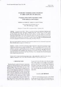
Transactions of the VŠB – Technical University of Ostrava No. 1, 2015, Vol. 15, Civil Engineering Series paper #02 Joanna BZÓWKA1, Anna JUZWA2, Konrad WANIK3, Lidia WANIK4, Tomasz ŻYREK5 DISCUSSION ON THE INFLUENCE OF VARIOUS TECHNOLOGICAL PARAMETERS ON JET GROUTING COLUMNS GEOMETRY Abstract One of the most popular elements created by using jet grouting technology are columns. During designing such columns, it is a problem of estimating their shape and dimensions. The main factors that influence on columns geometry are soil characteristic and technological parameters. At the frame of Authors scientific research, following technological factors were taken into account: system of jet grouting, injection pressure, dimension of nozzles and rotation speed during injection. In the paper some results of the field tests of jet grouting columns are presented. Keywords Jet grouting system, single fluid system, double fluid system, parameters of jet grouting.
1 INTRODUCTION One of the main problem of designing jet grouting foundations is determining the real dimension of jet grouting columns and a compressive strength of cement grout material [2, 3, 9]. Analytical models which are available in literature estimate the approximate diameter of columns. However, they require a large amount of additional information that is not always known. Currently, the best way of determining the diameter of jet grouting columns in known watersoil conditions is making test columns, then excavating and making an inventory. Some results of the tests carried out for jet grouting columns are described in [1]÷[6] and [8]÷[10]. This paper presents the study of the diameter of jet grouting columns and the compressive strength of cement grout material performed by research team of Department of Geotechnics and Roads of the Silesian University of Technology. In situ tests were carried out in Bojszowy Nowy in the trial field provided by the company Przedsiębiorstwo PPI Chrobok S.A. 16 jet grouting columns were performed, using single and double jet grouting systems. Each column was 4.0 m long. Before forming columns, geological surveys were
1
2
3
4
5
DSc., PhD., CEng., Assoc. Prof. Joanna Bzówka, Department of Geotechnics and Roads, Faculty of Civil Engineering, The Silesian University of Technology, Akademicka 5 St., 44-100 Gliwice, Poland, phone: (+48) 237 28 73, e-mail:
[email protected]. MSc., CEng Anna Juzwa, Department of Geotechnics and Roads, Faculty of Civil Engineering, The Silesian University of Technology, Akademicka 5 St., 44-100 Gliwice, Poland, phone: (+48) 237 28 73, e-mail:
[email protected]. MSc., CEng Konrad Wanik, Department of Geotechnics and Roads, Faculty of Civil Engineering, The Silesian University of Technology, Akademicka 5 St., 44-100 Gliwice, Poland, phone: (+48) 237 28 73, e-mail:
[email protected]. MSc., CEng Lidia Wanik, Department of Geotechnics and Roads, Faculty of Civil Engineering, The Silesian University of Technology, Akademicka 5 St., 44-100 Gliwice, Poland, phone: (+48) 237 28 73, e-mail:
[email protected]. MSc., CEng Tomasz Żyrek, Department of Geotechnics and Roads, Faculty of Civil Engineering, The Silesian University of Technology, Akademicka 5 St., 44-100 Gliwice, Poland, phone: (+48) 237 28 73, e-mail:
[email protected].
1 Unauthenticated Download Date | 1/21/16 2:26 AM
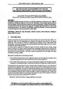
carried out. 2 drilling holes of 10 m length and 4 CPTU tests of 10 m length were performed [7]. The geological profile consists of (Fig. 1): layer I – uncontrolled embankment consists clay and sand, layer IIa – fine and medium sand, ID = 0.44; Φ=31.93°; c=0; M0=25.08 MPa, layer IIb – fine and medium sand, ID = 0.78; Φ=36.46°, c=0; M0=98.44 MPa, layer IIc – clay with organic part, IC = 0.62, Φ=18.96°, c=9.20 kPa; M0=7.76 MPa.
Fig.1: Geological profile [7] The weakest part of the ground is layer IIc which has organic parts (muds and clay) from 2.2 to 4.0 m below the surface. Thickness of these deposits is around 1.2 m. The water is in sandy soil. The level of ground water table is from 4.5 to 4.9 below the surface.
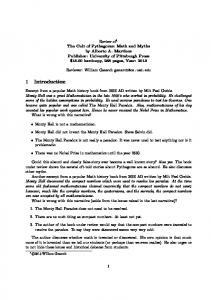
2 IN SITU TESTS At the trial field 8 single and 8 double jet grouting columns were performed. Following technological factors were taken into account: system of jet grouting, injection pressure, dimension of nozzles and rotation speed during injection. For the grout CEM II 32.5 was used (w/c = 1.0, density of cement grout 1.5 g/cm3). Forming time for all columns was equal 120 s/m. The columns were formed using two different injection pressures: 18 or 36 MPa. Also two different nozzles diameters were used: 2.8 and 4.0 mm. Rotation speed of the monitor was equal 12 or 25 rot./min. Compressed air flow rate for double fluid system was equal 5 m3/min. Spacing between single jet grouting columns was equal 2.0 m. Because of greater impact of cement grout with compressed air in soil, the spacing between double jet grouting columns was different: from 2.0 to 3.0 m. Some months later, the jet grouting columns were excavated up to 2.5 m below the surface and measured (Fig. 2÷3). Diameters of single jet grouting columns were at the range of 85÷115 cm and diameters of double jet grouting columns were at the range of 135÷190 cm. Making an inventory confirmed that using additional medium of compressed air causes creating bigger diameters of jet grouting columns.
2 Unauthenticated Download Date | 1/21/16 2:26 AM
a)
b)
Fig.2: Excavated jet grouting columns (own photos)
3 STRENGTH TESTS At the beginning, samples of cement grout material from columns were taken during injection process. The samples had cubic shape with sides equal 15 cm (Fig. 4). Unconfined compressive strength tests were performed after 28 days of maturation in the laboratory of Faculty of Civil Engineering at the Silesian University of Technology. The values of unconfined compressive strength for single jet grouting columns was at the range of 3.0÷7.0 MPa, and for double jet grouting columns at the range of 1.5÷3.0 MPa.
3 Unauthenticated Download Date | 1/21/16 2:26 AM
a)
b)
c)
d)
Fig.3: View of excavated jet grouting columns formed by: a) & b) single fluid system; c) & d) double fluid system (own photos)
Fig.4: Samples of cement grout material taken from columns during injection process (own photo) In order to determine the real unconfined compressive strength of cement grout materials core samples of jet grouting columns were drilled. Diamond coring system Hilti DD500 was used. Core drilling bit of 1500 mm length and 110 mm of diameter was used. As a result samples of 100 mm diameter from 4.0 m depth were taken (Fig. 5). Unconfined compressive strength tests were performed in the laboratory of Faculty of Civil Engineering at the Silesian University of Technology.
4 Unauthenticated Download Date | 1/21/16 2:26 AM
Cylindrical samples of cement grout material were prepared with following dimensions: 200 x 100 mm and 100 x 100 mm (Fig. 6).
Fig.5: Core samples taken from jet grouting columns (own photo) Average value of unconfined compressive strength for single jet grouting columns was equal 9.5 MPa (from 4.0 to 35.0 MPa), while average value of unconfined compressive strength for double jet grouting columns was equal 2.0 MPa (from 1.0 to 4.5 MPa). It should be noted that in many cases the samples had damages, loss and flaking that had an effect on the lower value of unconfined compressive strength. After studies, it was found that the greater impact on the value of the unconfined compressive strength of cement grout material have: - type of injection, - type of soil in which columns are formed, - the amount of cement grout pumped which depends on injection pressure and nozzles diameter. Research also shows that when the smaller value of rotation speed of the monitor and the larger columns diameters, the smaller value of unconfined compressive strength of cement grout material.
a)
b) c) Fig.6: The unconfined compressive strength tests of cement grout material: a) sample of single jet grouting column, b) & c) samples of double jet grouting columns (own photos)
5 Unauthenticated Download Date | 1/21/16 2:26 AM
4 CONCLUSIONS The scientific research confirms that greater diameter of jet grouting columns are provided by using double fluid jet grouting system. The higher value of unconfined compressive strength is obtained for single fluid jet grouting system. ACKNOWLEDGEMENT The coauthors: Anna Juzwa, Konrad Wanik, Lidia Wanik and Tomasz Żyrek – received a grant of the DoktoRIS project – scholarship program for innovative Silesia region co–financed by the European Union of the European Social Fund.
[1] [2]
[3]
[4]
[5]
[6]
[7]
[8] [9]
[10]
REFERENCES BZÓWKA J. Interaction of jet grouting columns with subsoil. Monograph ed. by The Silesian University of Technology, Gliwice 2009 (in Polish). BZÓWKA J.& JUZWA A. & WANIK L. Selected problems connected with the use of the jet grouting technique. Proceedings of the 18th International Conference on Soil Mechanics and Geotechnical Engineering, Paris 2013, pp. 2437-2440. BZÓWKA J. & JUZWA A. & WANIK L. & ŻYREK T. Innovative tests of jet grouting columns (Innowacyjne badania kolumn iniekcyjnych). Geoinżynieria drogi mosty tunele. 2014, No. 4, pp. 50-51 (in Polish). BZÓWKA J. & WANIK L. & WANIK K. Technological process of jet grouting technique. Seminar on Reinforcement, Sealing and Anchoring of Rock Massif and Biulding Structures 2013, Ostrava 2013, pp. 100-105. MODONI G. & BZÓWKA J. Analysis of foundations reinforced with jet grouting. ASCE Journal of Geotechnical and Geoenvironmental Engineering. Vol. 138, No. 12, December 2012, pp. 1442-1454. MODONI G. & WANIK L. & GIOVINCO G. & BZÓWKA J. & LEOPARDI A. Numerical analysis of submerged flows for jet grouting. Proceedings of the Institution of Civil Engineers – Ground Improvement, paper 1400012; DOI: 10.1680/grim.14.00012; ISSN:1755-0750; EISSN: pp. 1755-0769. P.P.B.&R.G. GEOSTANDARD Sp. z o.o. Geotechnical documentation of recognizing soilwater conditions at the field test in Bojszowy Nowe (Dokumentacja geotechniczna określająca warunki gruntowowodne na poletku doświadczalnym w Bojszowach Nowych), Wrocław 2012 (in Polish). WANIK K. Selected design and technological conditions of jet grouting application. Inżynieria i Budownictwo, No. 2, 2010, pp. 68-70 (in Polish). WANIK L. & BZÓWKA J. Influence of selected factors on jet grouting columns geometry. Zeszyty Naukowe Politechniki Rzeszowskiej, Budownictwo i Inżynieria Środowiska, z. 59 (3/12/IV), Rzeszów 2012, pp. 117-124 (in Polish). WANIK L. & MODONI G. Numerical analysis of the diffusion of submerged jets for jet grouting application. IARG 2012 Incontro Annuale Recircatori di Geotecnica, Padova (Italy), July 2012.
Reviewers: Ing. Věra Glisníková, CSc., Institute of Geotechnics, Faculty of Civil Engineering, Brno University of Technology. Czech Republic. Prof. Ing. Jozef Hulla, DrSc., Department of Geotechnics, Faculty of Civil Engineering, Slovak University of Technology in Bratislava. Slovak Republic.
6 Unauthenticated Download Date | 1/21/16 2:26 AM