Proceedings of 2010 IEEE Student Conference on Research and Development (SCOReD 2010), 13 - 14 Dec 2010, Putrajaya, Malaysia
3D RFID-Based Library Search System Application Development Terence Jerome Daim
Razak Mohd Ali Lee
School of Engineering and Information Technology University Malaysia Sabah Kota Kinabalu, Malaysia
[email protected]
School of Engineering and Information Technology University Malaysia Sabah Kota Kinabalu, Malaysia
[email protected]
Abstract—Measuring and determining RFID-tagged book location is an application development for the library search system namely 3D RFID-based library search system. This paper presents the development of this application which includes the application execution flow and as well as the laboratory scale system structure.
RFID reader, antenna and transponder
•
Search system software program
•
System server
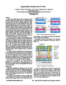
The first component of the system which consists of an RFID reader, an antenna and transponder are the RFID hardware elements that are required for the system operation. The “Search system software program” component consists of a software program that performs the localization process of the localization system. The software program also acts as middleware software that interfaces between the RFID reader and the system server. This allows user to control the RFID reader for various functions such as increase in the RFID reader output power level using only the software program graphical user interface which is host in the system server. The “System server” component which is basically can be any personal computer capable of running Microsoft Windows XP or Vista operating system and has either Universal Service Bus (USB) or Ethernet connection port. The purpose of the system server is to host the “Search system software program” where the software program is installed inside the system server.
Keywords-RFID; Localization system
I.
•
INTRODUCTION (HEADING 1)
Radio Frequency Identification (RFID) is a contactless identification technology working on the physical basis of alternating electromagnetic field [1] that can be used to electronically identify, track and store information about groups of products or individual items. RFID system consists of three main components mainly the antenna, reader and transponder. The antenna serves to facilitate communication between the transponder and the reader. The reader is responsible to read and processes transponder data. The reader is also responsible for interfacing with a host computer [2]. In a typical library, the task of locating a book is first to head to the library’s search system and search for the location details of the particular book. The usual location details are for example the level of which the shelve that contains the book resides and the label detail of the shelves. For any normal case it is usually sufficient to locate the book by using the location details provided but what if the book is not in the location according to the details given? This case is often occurring because library books are often removed and not returned to their original location. The task of locating and returning these books to their original locations would become even harder. Eventually, these books would be mixed up and not rearrange back to their proper places. In order to overcome this problem, RFID technology is being employed in the development of a library search system namely 3D RFID-Based Library Search System [3]. The purpose of this search system is to provide library users with the capability to track and locate a book in a library regardless it has been misplaced by other users or relocate to another location. Referring to Figure 1, the search system which makes use of RFID technology consists of three main components namely:
978-1-4244-8648-9/10/$26.00 ©2010 IEEE
Figure 1. System Components.
107
the host computer for control and software program execution purposes.
The development of this system is divided into several phases. Previous phase concentrates more on the study of the relationship between the reader’s output power and detected transponder distance which had been conducted and presented in [4]. This relationship study was conducted in order to collect and analyze data to proceed for the next development phase which is to develop an application to perform search function operation. This development is presented in this paper. The balance of this paper is organized as follows: The methodology used for the application development which includes explanation of a laboratory scale system structure and application execution flow is described in section two while section three provides the system accuracy test and result. The last section which is section four provides the conclusion. II.
METHODOLOGY
A. Test Sample This work solely concentrates on the development of the localization system without taking into account the different sizes of books and types of papers used. The reason for this is to ensure the development of the localization system will not be affected by this inconsistency. Hence, test samples with the same characteristics and dimensions are specifically made for this work. The test sample as depicted in Figure 2 consisted of “Double A” branded 80gsm A4 size printing papers bounded together to form a dimension of 0.3m x 0.2m x 0.05m. This is to simulate the average consistency and characteristic of a typical library book. A total of sixteen test samples are used throughout this work.
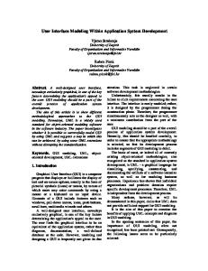
Figure 3. Lab scale system layout
Figure 4 depicts the two-tier book shelf of the lab scale system layout being divided and labelled into eight sectors. Each sector will holds two equally spaced test samples. The positions of these test samples were marked and labelled ranging from 1A to 8B according to Figure 4. Separators are installed between the test samples to prevent the test samples from having surface contact with each other. The transponder panels (left panels) of sector 2 – 4 and sector 6 – 8 are affixed with three transponders respectively which will act as reference transponders. These reference transponders serve as reference points to facilitate in the system searching process. One of the test samples is tagged with a transponder and labelled with a red sticker to differentiate it with other test samples. This specific test sample will act as the item of interest or target test sample that will be searched by the system
Figure 2. Test Sample
B. Laboratory Scale System Structure The laboratory scale system structure is depicted in Figure 3. The system structure consists of a specifically constructed two-tier bookshelf, a host computer, RFID reader, and two antennas. The two antennas which are connected to the RFID reader are placed on the left side near the two-tier book shelf, one for each bookshelf level. The RFID reader is connected to
Figure 4. Two-tier book shelf divided into eight sectors
108
C. Equipments Figure 5, 6 and 7 shows the reader, antenna and transponder used in this experiment measurement respectively. The reader is an Ultra High Frequency (UHF) reader from CAEN RFID which has a long range detection capability (approximately 5-6 meters depending on transponder type) with operating frequencies spanning from 865.6 MHz till 867.6MHz. This reader is also compliance with ISO 18000-6B, Philips UCODE EPC 1.19.
D. Localization Process To detect and determine the location of the transponder tagged test sample within the configured laboratory scale system structure, a localization process is developed. The following are the steps involve in the localization process of the system: 1) Retrieve all reference transponder recorded output power level. 2) Arrange the reference transponders recorded output power level according to the configuration as attached on the transponder panels.
P1 = ( R1 + R2 + R3 ) P2 = ( R4 + R5 + R6 ) P3 = ( R7 + R8 + R9 ) P4 = ( R10 + R11 + R12 ) P5 = ( R13 + R14 + R15 ) P6 = ( R16 + R17 + R18 )
(1)
3) Calculate the average output power level for each
Figure 5. CAEN RFID Long Range UHF reader.
P1
till P6 respectively.
P1 3 P A2 = 2 3 # P A6 = 6 3 A1 =
(2) 4) Retrieve test sample transponder output power level for both Antenna0 ( T 0 ) and Antenna1 ( T 1 ). 5) To determine on which level of the two-tier bookshelf the test sample resides, compare the value of the test sample transponder output power level and apply the conditions below:
Figure 6. CAEN RFID UHF circular polarized antenna.
Level0:
T0 < T1 L0 ,
T