Abstract â A new balanced power amplifier utilizing the reflected input is described. In general, the single-ended amplifier section in balanced amplifiers is not ...
2009 IEEE International Symposium on Radio-Frequency Integration Technology
A Balanced Power Amplifier Utilizing the Reflected Input Power Jongsik Lim1), Chunseon Park1), Jakyung Koo1), Hyeonwon Cha1), Yongchae Jeong2), Sang-Min Han1), and Dal Ahn1)
1) Dept. of Elec. and Comm. Engineering, Soonchunhyang University Eupnae-ri 646, Shinchang-myeon, Asan, Chungnam, 336-745, Rep. of KOREA 2) Dept. of Information and Comm. Engineering, Chonbuk National University Duckjin-dong, Duckjin-Gu, Jeonju, Chonbuk, 561-756, Rep. of KOREA Balanced Amplifiers are widely used in wireless communication system for improving wideband matching and doubling the output power from two identical single-ended amplifiers [3]-[6]. Most of power amplifiers are designed using the balanced topology in order to overcome the limitations of single-ended amplifier for a given power device. Generally, there exists a reflected power which is never ignorable when the input power is quite large unless the input matching is perfect. In many cases, 90o branch line hybrid couplers (BLHC) are adopted, and the reflected input power from two single-ended amplifiers are divided and appear at input and isolation ports of BLHC. The returned reflected signals at the input port are cancelled due to their out-of-phase property, while those at the isolation port are absorbed into the termination resistor. This is the summary why the input matching is improved inherently in balanced amplifiers with BLHC adopted. It is noted that the half of reflected input power are wasted due to the termination at the isolation port. If the wasted reflected input power is reused for amplification through another single-ended amplifier, i.e. the auxiliary amplifier, the final output performance would be improved. In this work, a new balanced amplifier with the auxiliary amplifier is proposed so that the reflected input power at the isolation port is injected again for improving output power. In addition, it is described that the efficiency and linearity performances are improved also using the proposed balanced amplifier.
Abstract — A new balanced power amplifier utilizing the reflected input is described. In general, the single-ended amplifier section in balanced amplifiers is not matched perfectly, so the reflected input power is terminated conventionally at the isolation port of branch line hybrid coupler. However in this work, the reflected power is injected into the auxiliary amplifier, and its output power is combined to the output power of balanced amplifier. Therefore final output power, power gain, and efficiency performances of the proposed balanced amplifier are highly improved compared to the conventional balanced amplifier. For the verification of the proposed balanced amplifier, a conventional balanced amplifier and the proposed balanced amplifier are fabricated and measured, and the measured results are compared. The proposed balanced amplifier shows an improvement in terms of output power(Pout), power gain, and power added efficiency (PAE) by 2.9 dB, 2.3 dB, and 7 %, respectively. Index Terms — Balanced amplifiers, auxiliary amplifiers, branch line hybrid coupler, power amplifiers.
I. INTRODUCTION Power amplifier is the one of key components to affect the performance of mobile communication system. The important issues on power amplifiers such as output power, efficiency and linearity have been studied deeply and widely for a long time. In order to give the smooth services to the rapidly increasing users with the limited frequency resource, the technical requirements for excellent output power, efficiency and linearity are essential [1]-[4]. The key issue for power amplifier development is basically focused on the improvement of output power, efficiency and intermodulation in order to minimize the negative effects and disturbances which might lead the performance degradation of communication systems. Linearity of power amplifiers is proportional to the device size, i.e. the output power. As the input power increases for a given power transistor, the nonlinearity increases faster than the fundamental output power. So a lot of linearization techniques have been studied extensively so far. The most popular linearization techniques in analog domain are feedforward and predistortion schemes [4].
978-1-4244-5032-9/09/$26.00 ©2009 IEEE
II. CONVENTIONAL BALANCED AMPLIFIER USING BLHC It is well known that the perfect matching of an amplifier is obtained only when the amplifier is matched for maximum gain with a narrow bandwidth [6]. However, in the design of power amplifiers, power matching is preferred rather than maximum high gain just as the noise matching should be achieved in the design of low noise amplifiers. Therefore the impedance matching will not be excellent and there must be the reflected input power somewhat inherently in the singleended topology. In order to overcome this problem and get the doubled power, balanced amplifier structures are widely adopted.
88
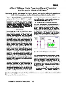
Fig. 2 illustrates the structure of the proposed balanced amplifier in this work. The conventional balanced amplifier is included as the basis of the proposed structure, and the third single-ended amplifier, i.e. auxiliary amplifier (“Amplifier C”) replaces the termination resistors of BLHCs at input and output sides. Two reflected signals at the input plane of both “Amplifier A” and “Amplifier B” are added to each other at the terminal (2) in Fig. 2 and reused as the input signal of “Amplifier C”. The reflected signal which appears at (2) is proportional to the original input power at (1), even its magnitude depends on the impedance matching of “Amplifier A” and “Amplifier B”. Fig. 3 shows the measured reflected power of the conventional balanced amplifier (BA) at (2), i.e. port 4 of the BLHC. As has been expected, the reflected power is never ignorable when the input power is quite large. For example, when the input power is +25dBm, the reflected power is around 19.5dBm in class A mode, and this is terminated in the conventional balanced amplifier. In addition, one can easily know that when “Amplifier A” and “Amplifier B” operate in class A mode, the magnitude of the reflected signal is the smallest. In other words, the smaller the conduction angle, the larger the reflected power exists in the conventional balanced amplifier.
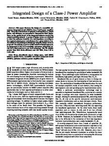
Fig. 1 shows a typical structure of balanced amplifiers with 90o BLHCs at the dividing and combining section. The input power is divided equally and injected into two single-ended sections. The amplified signal at the two paths is combined at the output port. If two single-ended sections are identical and no loss exists in the BLHCs ideally, the gain of the balanced amplifier is the same as the one of single-ended section. However the output power of the balanced amplifier is twice than that of the single-ended amplifier. In Fig. 1, S11a = S11b because two single-ended sections are identical, and in general S11a will not be perfect, so the reflected input signals at the input stage of single ended sections are divided into two paths again. One of them are added to each other at the isolation port and terminated finally, while the other one is cancelled at the input port because of an inherent out-of-phase characteristic cause from the properties of 90o BLHC. Strictly speaking, reflected signal at the isolation port might be considered as a waste of input power.
Fig. 1. Typical topology of balanced amplifiers with 90o branch line hybrid couplers.
III. THE PROPOSED BALANCED AMPLIFIER The worse the matching of “Amplifier A” and “Amplifier B” in Fig. 1, and the higher the input power, the more the wasted input power. However if the termination resistor at the isolation port is replaced by another gain stage, i.e. the third single-ended amplifier block, the third amplified signal here will be added to the output of the original balanced amplifier. So the improved performances are expected in terms of the main performance indexes such as output power, efficiency, and tow-tone IMD3, and so on.
Fig. 3. Measured reflected power of the conventional balanced amplifier (BA) at (2) in Fig. 2, i.e. port 4 of the BLHC.
One of the advantages of the proposed balanced amplifier in Fig. 2 is to reuse the reflected power as the input signal for the auxiliary amplifier, i.e. “Amplifier C”, while it is wasted in the conventional balanced structure. In general, when the conduction angle is smaller than 360o and further, the reflected power is larger than that of class A and more. So if this is injected into “Amplifier C”, the linearly amplifier signal is produced. Then the auxiliary amplifier contributes to the final output performance. Another advantage of the proposed balanced amplifier structure is that even when the balanced amplifier is saturated, the auxiliary amplifier still linearly operates, and this enables the proposed structure to produce the improved performances. So the output power from the “Amplifier C” plays a role in
Fig. 2. Structure of the proposed balanced amplifiers with an auxiliary amplifier.
89
improving the final performances. This principle is somewhat similar to the basic principle of Doherty amplifiers [3].
briefly. The measured P1dB is 32.1 dBm with PAE of 29% under the class AB operation.
IV. FABRICATION AND MEASUREMENT In order to verify the performances of the proposed balanced amplifier and compare them to those of the conventional balanced amplifier, we have built two balanced amplifiers and measured them at the frequency of 2110 ~ 2140MHz. Fig. 4 (a) and (b) show the photographs of the conventional balanced amplifier and the proposed balanced amplifier, respectively. It is seen that Fig. 4(b) contains the Fig. 4(a) exactly. The adopted BLHC for balanced amplifiers is RCP2150Q03 from RN2 Technologies, and has been fabricated using LTCC process. Fig. 5 shows the measured Sparameters of the BLHC itself on a test jig. In the measured graph of Fig. 5, the losses of test jig and connectors are not de-embedded, so it is noted that the S-parameters of the LTCC BLHC are excellent in terms of insertion losses, power division, port matching, and isolation.
Fig. 5. Measured S-parameters of the LTCC branch line hybrid coupler adopted in the balanced amplifiers (RN2 RCP2150Q03)
(a) Fig. 6. Measured performances of the conventional balanced amplifier (class AB case, BA : conventional balanced power amplifier)
TABLE I PERFORMANCE SUMMARY OF THE CONVENTIONAL BALANCED AMPLIFIER @ 2140MHZ Bias A AB B
(b)
P1dB [dBm] 32 32.1 32.9
Pgain @ P1dB [dB] 6.2 5.7 5
PAE [%] 28.9 29 33.5
Fig. 4. Fabricated balanced amplifiers (a) conventional structure (b) the proposed structure
Fig. 7 shows the measured performances of the proposed balanced power amplifier shown in Fig. 4(b). If we call the conventional BA section in Fig. 4(b) main amplifier for convenience, Fig. 7 shows the measured data when the main amplifier was biased with class AB, and the auxiliary amplifier with class A, AB, B, and C. In Fig. 7, the measured data out of Fig. 6 with class AB operation are plotted together for comparison.
Fig. 6 shows the measured performances of the conventional balanced power amplifier shown in Fig. 4(a), which had been measured first for the purpose of comparison. There were lots of measured data under various bias class, the measured ones with class AB mode are shown here as an example. Table I summarizes the measured performances
90
Table II summarizes the measured performances of the proposed balanced amplifier, which can be easily compared to Table I. The proposed balanced amplifier shows the P1dB of 34.78~35 dBm, which is larger than the data in Table 1 by around 3dB for class AB mode. In addition, the improved power gain and PAE are 1.1~2.3 dB and 3.3~7 %, respectively. These improved performances verify that the proposed balanced amplifier has great advantages than the conventional balanced amplifier before any popular linearization scheme is applied.
reflected signal at the isolation port is wasted because it is just terminated through the termination resistor. The amplified signal through the auxiliary amplifier is added at the output BLHC, and contributes to the performances improvement of balanced amplifier. The measurement showed that the proposed balanced amplifier has improved P1dB, Power gain, and PAE by 2.9 dB, 2.3 dB, and 7 %, respectively, for the class AB bias mode, even though they slightly depend on the bias class of the auxiliary amplifier. REFERENCES [1] M. Iwamoto, A. Williams, P.F. Chen, A. G. Metzger, L. E. Larson, P. M. Asbeck, "An Extended Doherty Amplifier With High Efficiency Over a Wide Power Range", IEEE Trans. Micro. Theory Tech., vol. 49, No. 12, pp. 2472-2478, Dec. 2001. [2] P. B. Kenington, R. J. Wilkinson, and J. D. Marvill, "Power Amplification Techniques for Linear TDMA Base Station", IEEE Global Telecommunication Conf., vol. 1, pp. 74-78, Dec. 1992. [3] S. C. Cripps, RF Power Amplifier Wireless Communication, Artech House, 1999. [4] J. L. B. Walker, High Power GaAs FET Amplifiers. Artech House, 1993. [5] D. M Pozar, Microwave Engineering, 2nd ed. New York: Wiley, pp. 570-573, 1998. [6] G. Gonzalez, "Microwave Transistor Amplifiers analysis and design", Second ed. Prentice Hall, pp. 348-432, 1996.
Fig. 7. Measured performances of the proposed balanced amplifier (BA : conventional balanced power amplifier, NBPA : (the proposed) new balanced power amplifier)
TABLE II PERFORMANCE SUMMARY OF THE PROPOSED BALANCED AMPLIFIER @ 2140MHZ Bias (BA + Aux) AB + A AB + AB AB + B AB + C
P1dB [dBm] 34.96 34.9 34.78 35
Pgain @ P1dB [dB] 8 7.7 7.1 6.8
PAE [%] 33.2 33.4 32.3 36
V. CONCLUSION A new balanced amplifier has been proposed in this work, and verified through the measurement. The proposed balanced amplifier adopts an auxiliary amplifier, connected to the isolation port of BLHC, in order to reuse the reflected signal. In the conventional balanced amplifiers adopting BLHC, the
91