IEEE - 31661
A Battery-based Constant Current Source (Bb-CCS) for Biomedical Applications Tushar Kanti Bera, Manobjyoti Saikia, J. Nagaraju Department of Instrumentation and Applied Physics, Indian Institute of Science, Bangalore Bangalore - 560012, Karnataka, INDIA Email:
[email protected] Abstract-A constant current source is essential for impedance measurement techniques in several biomedical applications. The impedance measurement studies in biomedical applications such as bioelectrical impedance analysis (BIA), electrical impedance plethysmography (IPG), electrical impedance myography (EIM), electrical impedance cardiography (ICG), electrical impedance spectroscopy (EIS), electrical impedance tomography (EIT) all need a high precision impedance measurement circuit with high signal to noise ratio (SNR). Moreover the impedance measurement circuit applied to the biomedical, clinical or medical applications such as human subject studies should have a better patient safety. In this direction a Battery-based Constant Current Source (Bb-CCS) is developed for biomedical applications. The Bb-CCS is developed with a modified Howland current source (MHCS) fed by a battery based power supply (BBPS). The current amplitude, frequency and waveforms are set as the circuit variables which are found as adjustable as per the requirements. The frequency responses, load response, Fast Fourier Transform (FFT) of the Bb-CCS are studied and results show that the Bb-CCS can be suitably used for multifrequency impedance measurement methods in biomedical applications. Keywords - Bioelectrical Impedance, constant current source, Battery-based Constant Current Source (Bb-CCS), biomedical applications, modified Howland current source (MHCS), battery based power supply (BBPS), frequency response, load response, Fast Fourier Transform (FFT).
I. INTRODUCTION Electrical impedance of biological tissues [1-3] and their other electrical properties [4-9] such as resistivity [4-5], conductivity [6], permittivity [7-8] and admittivity [9] all have their own complex frequency responses and all are found as the function of tissue composition and signal frequency [4-10]. The frequency response of the electrical impedance of the biological tissues varies with physiological and physiochemical health status. Frequency response of the bioelectrical impedance varies from subject to subject [10-17] and it may also vary from one tissue part to another tissue part within a particular subject. Moreover, the bioelectrical impedance of biological tissues varies with the measurement directions for the same tissue called anisotropic tissues [9]. As the bio-impedance changes with the variations in tissue health status [1, 18-19], the frequency response studies of bioelectrical impedance can provide a lot of information about the anatomy and physiology of the tissue under test. Bioelectrical impedance methods measure the electrical
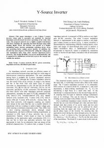
impedance of the object at a single frequency or at multiple frequencies from the set of voltage-current data. The voltagecurrent data are generally measured at the tissue surface by injecting a constant voltage signal or current signal using a constant voltage source [20-21] or constant current source [21-26] respectively, through the surface electrodes [27-28] with two electrode or four electrode methods (Fig. 1). In two electrode method the current injection and voltage measurements are conducted through the same electrodes pairs (Fig. 1a) and hence, it is known as two-electrode technique [16]. On the contrary, the four-probe method [16] injects the frequency dependent current signal (I(ω)) through two-electrodes (called current electrodes or driving electrodes) as shown by the red electrodes in Fig. 1b and the frequency dependent electric potential (V(ω)) developed, is measured [16] across other two electrodes (called voltage electrodes or sensing electrodes) blue electrodes (Fig. 1b). The frequency dependent electrical impedance Z(ω) is calculated by the Ohm’s law for alternating circuits which is given by: Zω
Vω Iω
(1)
The Z (ω) is the transfer function of the object in which the applied current signal (I(ω)) and the voltage data (V(ω)) are input signal and output signals respectively.
Figure-1: Electrical impedance measurement schematic using two-probe or four-probe technique (a) impedance measurement using two-probe technique, (b) impedance measurement using four-probe technique.
A constant current source [21-26] is essential for impedance measurement techniques in several biomedical applications such as bioelectrical impedance analysis (BIA) [29-32], electrical impedance plethysmography (IPG) [33-34], electrical impedance myography (EIM) [35], electrical impedance cardiography (ICG) [36-38], electrical impedance spectroscopy (EIS) [39-45], electrical impedance tomography (EIT) [46-56] and so on. The BIA, IPG, EIM, ICG, EIS and
1 4th ICCCNT 2013 July 4 - 6, 2013, Tiruchengode, India
IEEE - 31661
number of passive circuit elements [68]. The MAX038 is a high-frequency, precision function generator and generates high quality, high frequency triangle, saw-tooth, sine, square, and pulse waveforms with a minimum number of external components. The frequency of the VCO is made adjustable by changing the values of frequency controller capacitance (Cf) and resistance (Rin). The VCO is developed to generate a pure sinusoidal signal with an adjustable frequency from 10 Hz to 10 MHz. The VCCCS is basically a modified Howland based voltage controlled constant current source (Fig. 3) developed with two AD829 Op-Amps. The AD829 [69] is a low noise (1.7 nV/√Hz), high speed op amp with custom compensation that provides the user with gains of ± 1 to ± 20 while maintaining a bandwidth greater than 50 MHz [69]. The current amplitude of VCCCS is controlled by different values of resistors connected through a resistor bank (Fig. 3). An 8pin DIP switch based resistor bank (Fig. 3) is developed with eight resistors (RS1, RS2, RS3, …, RS7, RS8) and is used to control the current amplitude in VCCCS. The resistors RS1, RS2, RS3 , …, RS7, RS8 are individually connected with the eight switches S1, S2, S3, …, S7, S8 which connect these resistors to provide the eight different current amplitudes (I1, I2, I3, …, I7, I8) in the VCCCS. When any one of the switches (say, S3) is operated, it connects the corresponding resistor (RS3) in the VCCCS circuit which provides a particular amplitude of current signal (I3) (Fig. 3). The current amplitude of the VCCCS is simultaneously sensed and measured by putting a current sensing resistor (RSENCE) in series with the load (RL) as shown in Fig. 3.
EIT all are studied either with a constant current injector circuit or readymade impedance measuring instruments. Being the established and proven methods, the BIA and EIS instrument are available in market. But for available ICG, IPG the instruments are less in number. Being a bioimpedance tomographic technique EIT has several advantages over other impedance methods and other tomographic methods and hence it is being studied by a number of research groups. As the number of available EIT instruments is very few, the constant current injectors are usually developed, studied and evaluated in EIT phantom studies [57-67]. To obtain a higher measurement accuracy BIA, IPG, EIM, ICG, EIS, EIT all need a high precision impedance measurement circuit or impedance measurement instrument such as impedance analyzer (Fig. 2) with high signal to noise ratio (SNR). As the biological tissues have variable impedance response over a wide range of signal frequency, the current source with multifrequency application is always advantageous. Moreover the impedance measurement circuit applied to the clinical and medical applications such as measurement studies on human subject should have a better patient safety. In this direction a multifrequency Battery-based Constant Current Source (BbCCS) is developed and studied in biomedical applications. The Bb-CCS is developed with a modified Howland current source (MHCS) powered by a battery based power supply (BBPS). The amplitude, frequency and waveforms of the output current signal are set as the circuit variables which are made adjustable as per the practical applications. The frequency responses, load response, Fast Fourier Transform (FFT) of the output current signal of the Bb-CCS are studied to evaluate the Bb-CCS. Bb-CCS is also found suitable for the impedance measurement processes in biomedical applications.
Figure-3: Schematic of the VCCCS with the resistor bank for setting the different current amplitudes.
B. Battery Based Power Supply (BBPS) A battery based power supply (BBPS) is developed (Fig. 4) for increasing the signal to noise ratio (SNR). The BBPS is developed with two 12 V sealed lead acid rechargeable batteries and a battery charging circuit (BCC) developed to generate a pure ±12 V dc supply required for charging the batteries. The BCC (Fig. 4) is developed with a filterregulator-filter (FRF) block developed as per the battery power consumption. The BCC is fed by the power supply obtained from the bridge rectifier circuit (BRC). The BBPS is charged with a transformer based power supply (TBPS) as shown in Fig. 4 and can be used for feeding the MHCS directly if requires. In TBPS a 240: (24:0:24) volts, 1 A, 1 ϕ, step down, center tapped (secondary), iron core transformer is used to step down the ac main supply (240 V, ac, 50 Hz).
Figure-2: Schematic of the electrical impedance spectroscopy (EIS) studies on biological materials with four-probe technique using an impedance analyzer [current signal is injected through the outer (shown in red) electrodes and the voltage is measured across the inner (shown in blue) electrodes].
II. MATERIALS AND METHODS A. Modified Howland current source (MHCS) Modified Howland current source (MHCS) is developed with a voltage Controlled Oscillator (VCO) and a voltage controlled constant current source (VCCCS). The VCO is developed with MAX038 IC connected with a minimum
2 4th ICCCNT 2013 July 4 - 6, 2013, Tiruchengode, India
IEEE - 31661
The 240 volts (r.m.s.) mains is stepped down to 24 volt (r.m.s.) and is fed to the BRC connected to a the filterregulator-filter (FRF) block (Fig. 4). The filter-regulator-filter (FRF) block is developed with standard regulator ICs (78XX and 79XX series) as shown in Fig. 4. As per the requirement, the different dc voltage levels (in ±5 V dc or ±9 V or ±12 V dc) are obtained from the battery output (±12V dc supply) using voltage divider circuits. All the circuit blocks are developed in such a way that they can operate from 5 V to 18 V range except VCO as MAX038 IC only works at 5 V. But for low power consumption the whole instrumentation is operated at 5 V dc supply and the instrumentation is found suitable for biomedical applications. An isolation transformer (1:1) is also used to isolate the imaging object from the electric power lines for safety. Isolation transformer provides the isolation between the subject under test (SUT) and the measuring instruments and it is generally used to protect the SUT against electric shock, to suppress electrical noise, or to transfer power between current source and the SUT.
BIA, IPG, EIM, ICG, EIS, EIT etc. The output signal of the battery based constant current source (Bb-CCS) is also studied at different frequencies (Fig. 6) and the Bb-CCS is found suitable for multifrequency bioimpedance methods.
Figure-5: Output signal waveform studies and its frequency responses of BBPS based constant current source (Bb-CCS) obtained in digital storage oscilloscope (a) output signal, (b) FFT of the output signal.
Figure-4: Schematic of the Battery Based Power Supply (BBPS).
III. RESULTS AND DISCUSSION Frequency response of the VCO show that the VCO generates pure sinusoidal, triangular and square waveforms from 10 Hz to 10 MHz. Frequency response of the VCCCS show that the VCCCS generates pure current signal from 10 Hz to 1 MHz with sinusoidal, triangular and square waveforms. The output signal of the VCCCS is studied at 50 kHz in DSO and the signal is saved to obtain the FFT of the signal. FFT shows that the signal is generated at 50 kHz with negligible noise and hence it is found very suitable for biomedical application. Fig. 5a and Fig. 5b show the output current signal of the Bb-CCS and its FFT obtained for 1 kΩ resistive load at 50 kHz using DSO. FFT shows that the current signal is generated at 50 kHz almost without noise and hence it is found very suitable for biomedical applications like
Figure-6: Waveform studies and the frequency response studies of output signal of the Bb-CCS obtained in digital storage oscilloscope (a) signal at 25 kHz, (b) FFT of the signal a), (c) signal at 50 kHz, (d) FFT of the signal c), (e) signal at 100 kHz, (f) FFT of the signal e), (g) signal at 250 kHz, (h) FFT of the signal g), (i) signal at 500 kHz, (j) FFT of the signal i).
3 4th ICCCNT 2013 July 4 - 6, 2013, Tiruchengode, India
IEEE - 31661 [10] Bera TK, Seo JK, Kwon H and Nagaraju J, A LabVIEW Based Electrical Bio-Impedance Spectroscopic Data Interpreter (LEBISDI) for Studying The Equivalent Circuit Parameters of Biological Tissues, 15th International Conference on Electrical Bio-Impedance (ICEBI) and 14th Conference on Electrical Impedance Tomography (EIT), Germany, 2013, pp 77. [11] Ackmann JJ, Complex Bioelectric Impedance Measurement System for the Frequency Range from 5 Hz to 1 MHz, Annals of Biomedical Engineering. 1993; 21:135-146. [12] Bera TK and Nagaraju J, Electrical Impedance Spectroscopic Study of Broiler Chicken Tissues Suitable for The Development of Practical Phantoms in Multifrequency EIT, J Electr Bioimp, vol. 2, pp. 48–63, 2011. [13] B. Bodakian, The Dielectric Properties of Meat, IEEE Transactions on Dielectrics and Electrical Insulation Vol. 1 No. 2, April 1994, 181-187. [14] Ackmann JJ, Seitz MA., Methods of complex impedance measurements in biologic tissue, Crit Rev Biomed Eng. 1984; 11(4): 281-311. [15] Cha K, Chertow GM, Gonzalez J, Lazarus JM, and Wilmore DW, Multifrequency bioelectrical impedance estimates the distribution of body water, J Appl Physiol. 1995; 79:1316-1319. [16] Bera TK and Nagaraju J, Electrical Impedance Spectroscopic Study of Broiler Chicken Tissues Suitable for The Development of Practical Phantoms in Multifrequency EIT, J Electr Bioimp, vol. 2, pp. 48–63, 2011. DOI:10.5617/jeb.174 [17] Bauchot AD, Harker FR, Arnold WM, The use of electrical impedance spectroscopy to assess the physiological condition of kiwifruit, Volume 18, Issue 1, January 2000, Pages 9–18 [18] Bera TK and Nagaraju J, A Multifrequency Constant Current Source for Medical Electrical Impedance Tomography, Proceedings of the IEEE International Conference on Systems in Medicine and Biology 2010 (IEEE ICSMB 2010), India, Dec’2010, India, pp 278-283. [19] P. Bertemes-Filho, A. S. Paterno, R. M. Pereira, Multichannel Bipolar Current Source Used in Electrical Impedance Spectroscopy: Preliminary Results, World Congress on Medical Physics and Biomedical Engineering, September 7 - 12, 2009, Munich, Germany, IFMBE Proceedings Volume 25/7, 2009, pp 657-660. [20] T R Qureshi, C R Chatwin and W Wang, Design of Wideband Voltage Source Having Low Output Impedance, Flexible Gain and Controllable Feedback Current for EIT Systems, 2012 2nd International Conference on Biomedical Engineering and Technology, IPCBEE vol. 34 (2012), IACSIT Press, Singapore, 45-50. [21] Youssoufa Mohamadou, Tong In Oh, HunWi, Harsh Sohal, Adnan Farooq, Eung Je Woo and Alistair Lee McEwan, Performance evaluation of wideband bio-impedance spectroscopy using constant voltage source and constant current source, Meas. Sci. Technol. 23 (2012) 105703 (10pp). [22] Alexander S Ross, G J Saulnier, J C Newell and D Isaacson, Current source design for electrical impedance tomography, Physiol. Meas. 24 (2003) 509–516 PII: S0967-3334(03)54203-4. [23] Jeong Whan Lee, Tong In Oh, Sang Min Paek, Jae Sang Lee, and Eung Je Woo, Precision Constant Current Source for Electrical Impedance Tomography, Proceedings of the 25" Annual International Conference of the IEEE EMBS, Cancun, Mexico, 2003, 1066-1069. [24] José Antonio Gutiérrez Gnecchi, Voltage Controlled Current Source (VCCCS) for Electrical Impedance Tomography (EIT) Measurements in the α and β Dispersion Frequency Ranges, 2010 Electronics, Robotics and Automotive Mechanics Conference, 677-681. [25] Bera TK and Nagaraju J, A Multifrequency Constant Current Source Suitable for Electrical Impedance Tomography (EIT), Proceedings of 2010 International Conference on Systems in Medicine and Biology, 1618 December 2010, IIT Kharagpur, India, pp 278-283. [26] Engr. Angelito A. Silverio, M.S., Engr. Angelina A. Silverio, M.A., M.S., A High Output Impedance Current Source for Wideband Bioimpedance Spectroscopy Using 0.35μm Tsmc Cmos Technology, International Journal of Engineering and Applied Sciences, 2012, December 2012. Vol. 1, No.2. 68-75. [27] Webster JG, Electrical impedance tomography, first edition. Adam Hilger Series of Biomedical Engineering Adam Hilger, New York, USA. 1990. [28] J. G. Webster, Medical Instrumentation: Principle and design, John Wiley & Sons, Hoboken, NJ, USA, 1995
The output signal of the battery based constant current source (Bb-CCS) is studied at different frequencies in DSO and the signals are saved to obtain the FFT of the signal. FFTs of the current signals are studied at all the frequencies. Results show that the Bb-CCS generates the current signal from 10 Hz -1 MHz with negligible noise and hence it is found very suitable for multifrequency bioimpedance methods like EIS, EIT etc. Results show that the Bb-CCS generates high accuracy current signals with an amplitude of 200 µA – 7.5 mA within a frequency range of 10 Hz to 1 MHz. Load response of Bb-CCS showed that Bb-CCS can drive up to 7.8 kΩ load with a supply voltage of 9 V for 1 mA supply. Bioimpedance studies like EIT and EIS show that Bb-CCS can suitably drive biological loads and works well with high accuracy and high SNR. Thus Bb-CCS is found suitable for impedance studies in biomedical applications studies with variable current amplitude (200 µA – 7.5 mA), multifrequency (10 Hz – 1 MHz), different current waveforms. IV. CONCLUSIONS Individual and combined frequency responses of VCO and VCCCS are studied. Results show that the output of the VCO remains constant up to 10 MHz. Frequency response of VCCCS showed that the current output of the VCCCS remains constant up to 1 MHz. The frequency response of the Bb-CCS is also studied and it is found suitable for multifrequency bioimpedance application from 10 Hz to 1 MHz. Thus Bb-CCS is found suitable for impedance studies in biomedical applications with variable current amplitude (200 µA – 7.5 mA), multifrequency (10 Hz – 1 MHz), different current waveforms. V. REFERENCES [1] [2]
[3]
[4]
[5] [6] [7] [8] [9]
A Orjan G. Martinsen, Sverre Grimnes, Bioimpedance and Bioelectricity Basics, Second Edition, Academic Press; 2 edition (April 21, 2008). Bolfe Vj, Ribas Si,Montebelo Mil & Guirro Rrj, Electrical Impedance Behavior of Biological Tissues During Transcutaneous Electrical Stimulation, Rev. bras. fisioter., São Carlos, v. 11, n. 2, p. 135-140, Mar./Apr. 2007. Muobarak J Tuorkey, Bioelectrical Impedance as a Diagnostic Factor in the Clinical Practice and Prognostic Factor for Survival in Cancer Patients: Prediction, Accuracy and Reliability, J Biosens Bioelectron Volume 3, Issue 4, 1000121. D. Haemmerich, O. R. Ozkan, J.-Z. Tsai, S. T. Staelin, S. Tungjitkusolmun, D. M. Mahvi4, J. G. Webster, Changes in electrical resistivity of swine liver after occlusion and postmortem, Med. Biol. Eng. Comput., 2002, 40, 29–33. L. A. Geddes and L. E. Baker, The Specific Resistance of Biological Material - A Compendium of Data for The Biomedical Engineer and Physiologist, , Med. & Biol Engng. Vol. 5. PP. 271-293. Bradley J. Roth, The Electrical Conductivity of Tissues, The Biomedical Engineering Handbook, 2 Edition, 2000 by CRC Press LLC. C Gabriel, S Gabriely and E Corthout, The dielectric properties of biological tissues: I. Literature survey, Phys. Med. Biol. 41 (1996) 2231–2249. Ronald Pethig, Dielectric and Electrical Properties of Biological Materials, Read More: Electromagnetic Biology and Medicine, 1985, Vol. 4, No. 2 : Pages vii-ix. Jin Keun Seo, Tushar Kanti Bera, Hyeuknam Kwon, and Rosalind Sadleir, Effective Admittivity of Biological Tissues as a Coefficient of Elliptic PDE, Computational and Mathematical Methods in Medicine Volume 2013 (2013), Article ID 353849, 10 pages.
4 4th ICCCNT 2013 July 4 - 6, 2013, Tiruchengode, India
IEEE - 31661 [29] Kyle UG, Bosaeus I, De Lorenzo AD, Deurenberg P, Elia M, G!omez JM, Heitmann BL, Kent-Smith L, Melchior JC, Pirlich M, Scharfetter H, Schols AMWJ, Pichard C, Bioelectrical impedance analysis - part I: review of principles and methods, Clinical Nutrition. 2004; 23: 1226-43. [30] Kyle UG, Bosaeus I, De Lorenzo AD, Deurenberg P, Elia M, Go´mez JM, Heitmann BL, Kent-Smith L, Melchior JC, Pirlich M, Scharfetter H, Schols AMWJ, Pichard C, Bioelectrical impedance analysis-part II: utilization in clinical practice, Clinical Nutrition. 2004; 23: 1430–1453. [31] Gudivaka R, Schoeller DA, Kushner RF, and Bolt MJG, Single and multifrequency models for bioelectrical impedance analysis of body water compartments, J Appl Physiol. 1999; 87(3): 1087-96. [32] Kahraman A, Hilsenbeck J, Nyga M, Ertle J, Wree A, Plauth M, Gerken G, Canbay AE, Bioelectrical impedance analysis in clinical practice: implications for hepatitis C therapy BIA and hepatitis C, Virology Journal. 2010; 7: 191. [33] Hill RV, Jansen JC, Fling JL., Electrical impedance plethysmography: a critical analysis, J Appl Physiol January 1967 22:(1) 161-8 [34] Nyboer J, Kreider MM and Hannapel L, Electrical Impedance Plethysmography A Physical and Physiologic Approach to Peripheral Vascular Study, Circulation. 1950;2:811-821. [35] Rutkove SB., Electrical impedance myography: Background, current state, and future directions, Muscle Nerve. 2009 Dec;40(6):936-46. [36] Griffths RW, Philpot ME, Chapman BJ, Munday KA., Impedance cardiography: non-invasive cardiac output measurement after burn injury, Int J Tissue React. 1981 Mar;3(1):47-55. [37] Schuster CJ, Schuster HP, Application of impedance cardiography in critical care medicine, Resuscitation. 1984 Mar;11(3-4):255-74. [38] Woltjer HH, Bogaard HJ and de Vries PMJM, The technique of impedance cardiography, European Heart Journal (1997) 18, 1396-1403 [39] Orazem ME, Tribollet B, Electrochemical Impedance Spectroscopy, (The ECS Series of Texts and Monographs), Wiley-Inter Sc., 2008. [40] Macdonald RJ, Impedance Spectroscopy, Annals of Biomedical Engineering. 1992; 20: 289-305. [41] Repo T, Paine DH and Taylor AG, Electrical impedance spectroscopy in relation to seed viability and moisture content in snap bean (Phaseolus vulgaris L.), Seed Science Research. 2002; 12: 17-29,. [42] Repo T, Laukkanen J and Silvennoinen R, Measurement of the Tree Root Growth Using Electrical Impedance Spectroscopy, Silva Fennica. 2005; 39(2): 159–166. [43] Barsoukov E, Macdonald JR, Impedance Spectroscopy: Theory, Experiment, and Applications, Wiley-Inter Sc.; 2 Ed. 2005. [44] Bera TK and Nagaraju J, Electrical Impedance Spectroscopic Studies of The Electronic Connectors of DIP Switch Based Multiplexers Suitable for Multifrequency Electrical Impedance Tomography, Biomedical Engineering, Narosa Publishing House, Proceeding of the International Conference on Biomedical Engineering 2011 (ICBME-2011), Manipal, India, 2011, pp 58-65. [45] Bera TK and Nagaraju J, Studying the Variations of Complex Electrical Bio-Impedance of Vegetables and Fruits under The Different Health Status, 15th International Conference on Electrical Bio-Impedance (ICEBI) and 14th Conference on Electrical Impedance Tomography (EIT), Germany, April 22–25, 2013, pp193. [46] Holder DS. Electrical impedance tomography: methods, history and applications (Series in Medical Physics and Biomedical Engineering). first edition, Institute of Physics Publishing Ltd. 2004. [47] Bera TK, Biswas SK, Rajan K and Nagaraju J, Improving Image Quality in Electrical Impedance Tomography (EIT) Using Projection Error Propagation-Based Regularization (PEPR) Technique: A Simulation Study, J Electr Bioimp, vol. 2, pp. 2–12, 2011. [48] Bayford RH. Bioimpedance Tomography (Electrical Impedance Tomography). Annual Review of Biomedical Engineering 2006;8:63-91. [49] Bera TK and Nagaraju J, Resistivity Imaging of A Reconfigurable Phantom With Circular Inhomogeneities in 2D-Electrical Impedance Tomography, Measurement, Volume 44, Issue 3, 2011, Pages 518-526. [50] Bera TK and Nagaraju J, Surface Electrode Switching of A 16-Electrode Wireless EIT System Using RF-Based Digital Data Transmission Scheme With 8 Channel Encoder/Decoder ICs, Measurement 45 541– 555, 2012 [51] Cheney M, Isaacson D and Newell JC. Electrical Impedance Tomography. SIAM Review, Society for Industrial and Applied Mathematics 1999;41(1):85-101.
[52] Bera TK, Biswas SK, Rajan K and Nagaraju J, Improving Conductivity Image Quality Using Block Matrix-based Multiple Regularization (BMMR) Technique in EIT: A Simulation Study, J Electr Bioimp, vol. 2, pp. 33–47, 2011. [53] Bera TK and Nagaraju J, Studying the Resistivity Imaging of Chicken Tissue Phantoms with Different Current Patterns in Electrical Impedance Tomography (EIT), Measurement, 45, 663–682, 2012 [54] Borcea L. Electrical impedance tomography. Topical Review, Inverse Problems 2002;18:R99–R136 [55] Bera TK and Nagaraju J, Elemental Resistivity Profile Analysis of EIT Images to Assess the Reconstructed Image Quality, International Journal of Information Processing, 7(1), 1-14, 2013.. [56] Bera TK and Nagaraju J, A MATLAB Based Boundary Data Simulator for Studying The Resistivity Reconstruction Using Neighbouring Current Pattern, Journal of Medical Engineering, Volume 2013, Article ID 193578, 15 pages. [57] Bera TK and Nagaraju J, A Stainless Steel Electrode Phantom to Study the Forward Problem of Electrical Impedance Tomography (EIT), Sensors & Transducers Journal, Vol. 104, Issue 5, 2009, pp. 33-40. [58] Bera TK and Nagaraju J, A Chicken Tissue Phantom for Studying An Electrical Impedance Tomography (EIT) System Suitable for Clinical Imaging, Sensing and Imaging: An International Journal, Volume 12, Numbers 3-4, 95-116, 2011. [59] Bera TK and Nagaraju J, A FEM-Based Forward Solver for Studying the Forward Problem of Electrical Impedance Tomography (EIT) with A Practical Biological Phantom, Proceedings of IEEE International Advance Computing Conference' 2009 (IEEE IACC - 2009), India, 67th March 2009, Patiala, Punjab, India, pp 1375 - 1381. [60] Bera TK and Nagaraju J, A Study of Practical Biological Phantoms with Simple Instrumentation for Electrical Impedance Tomography (EIT), Proceedings of IEEE International Instrumentation and Measurement Technology Conference (I2MTC2009), Singapore, 2009, pp 511-516. [61] Bera TK and Nagaraju J, A Simple Instrumentation Calibration Technique for Electrical Impedance Tomography (EIT) Using A 16 Electrode Phantom, Proceedings of The Fifth Annual IEEE Conference on Automation Science and Engineering (IEEE CASE 2009), India, Bangalore, Aug’2009, pp. 347-352. [62] Bera TK and Nagaraju J, Studying the Boundary Data Profile of A Practical Phantom for Medical Electrical Impedance Tomography with Different Electrode Geometries, Proceedings of The World Congress on Medical Physics and Biomedical Engineering-2009, Germany, 2009, WC 2009, IFMBE Proceedings 25/II, pp 925–929. [63] Bera TK and Nagaraju J, Gold Electrode Sensors for Electrical Impedance Tomography (EIT) Studies, IEEE Sensors Application Symposium 2011 (IEEE SAS 2011), USA, Feb’2011, USA, pp 24-28. [64] Bera TK, Biswas SK, Rajan K and Nagaraju J, A Model Based Iterative Image Reconstruction (MoBIIR) Algorithm for Conductivity Imaging in EIT Using Simulated Boundary Data, AIP Conference Proceedings Volume 1391, Optics 2011: International Conference on Light, Kerala, (India), May 2011, pp. 489-491. [65] Bera TK, Biswas SK, Rajan K and Nagaraju J, Improving the Image Reconstruction in Electrical Impedance Tomography (EIT) with Block Matrix-based Multiple Regularization (BMMR): A Practical Phantom Study, IEEE World Congress on Information and Communication Technologies 2011(WICT-2011), India, University of Mumbai, Mumbai, India, 2011, pp 1346-1351. [66] Bera TK, Biswas SK, Rajan K and Nagaraju J, Image Reconstruction in Electrical Impedance Tomography (EIT) with Projection Error Propagation-based Regularization (PEPR): A Practical Phantom Study, Lecture Notes in Computer Science, Springer, 2012, Volume 7135/2012, 95-105, ADCONS 2011. [67] Bera TK and Nagaraju J, A Multifrequency Electrical Impedance Tomography (EIT) System for Biomedical Imaging, IEEE International Conference on Signal Processing and Communications (SPCOM 2012), India, IISc - Bangalore, India pp 1-5. [68] Data Sheet, MAX038-high-frequency waveform generator, Maxim Integrated Products, Inc. CA 94086 [69] Data Sheet, AD829 - 120 MHz, High Speed, Low Noise Video Op Amp, Analog Devices, Inc
5 4th ICCCNT 2013 July 4 - 6, 2013, Tiruchengode, India