Debugging environment for both language containment and ... containment approach) (as in the verification tool COSPAN [12]). An alternative ... In building tran-.
HSIS: A BDD-Based Environment for Formal Verification A. Aziz, F. Balarin, S. T. Cheng, R. Hojati, T. Kam, S. C. Krishnan, R. K. Ranjan, T. R. Shiple, V. Singhal, S. Tasiran, H.-Y. Wang, R. K. Brayton and A. L. Sangiovanni-Vincentelli Department of EECS, University of California at Berkeley, Berkeley, CA 94720
Abstract Functional and timing verification are currently the bottlenecks in many design efforts. Simulation and emulation are extensively used for verification. Formal verification is now gaining acceptance in advanced design groups. This has been facilitated by the use of binary decision diagrams (BDDs). This paper describes the essential features of HSIS, a BDD-based environment for formal verification: 1. Open language design, made possible by using a compact and expressive intermediate format known as BLIF-MV. Currently, a synthesis subset of Verilog is supported. 2. Support for both model checking and language containment in a single unified environment, using expressivefairness constraints. 3. Efficient BDD-based algorithms. 4. Debugging environment for both language containment and model checking. 5. Automatic algorithms for the early quantification problem. 6. Support for state minimization using bisimulation and similar techniques. HSIS allows us to experiment with formal verification techniques on a variety of design problems. It also provides an environment for further research in formal verification.
1 Introduction In the design of digital systems, there are two different levels of verification, corresponding to the two major phases of design. The first phase of design is transferring ideas into an initial description, using a high-level description language, like VHDL or Verilog. Design verification is used at this level to answer the question “Is what I specified what I wanted?”. The second phase of design is synthesizing the initial description into a circuit which can be implemented. Implementation verification is used at this level to answer the question “Is what I synthesized what I specified?”; this capability is present to some degree in many synthesis packages today. There are two major approaches to design verification. The traditional approach is simulation, which is well-understood and has been applied widely in the design community. Designers are comfortable with simulation because thinking in terms of input patterns and expected output patterns is intuitive. However, exhaustive simulation is not feasible for even moderately sized systems. The second approach is formal design verification, which is the process of mathematically proving that a system possesses a given property. The theory behind this approach has been investigated over the last couple of decades, but only in the last five years have practical tools emerged. Formal design verification is equivalent to exhaustive simulation, but can often be performed in only a fraction of the time.
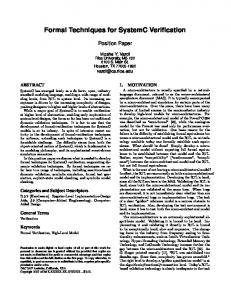
However, formal design verification is currently limited to relatively small designs, and the methods for specifying properties are complex to uninitiated users. We seek to improve the efficiency of verification so that larger designs can be verified, and to develop simpler methods for specifying properties. Of the various formal verification methods, the first to be used in design verification was theorem proving [11, 3]. These techniques are somewhat similar to the formal verification techniques used to verify the correctness of software written in programming languages. These verification techniques usually require extensive interactive use of human experts. There have been two recent approaches for verifying properties of systems described as state transition systems. One approach is to specify both the system and the properties as !-automata. The verification task is equivalent to verifying that the language of the system is contained in the language of the properties (the language containment approach) (as in the verification tool COSPAN [12]). An alternative approach of doing property verification is to specify the properties using temporal logic and perform model checking on the system specification to verify these properties [7]. Systems that manipulate these state-based systems explicitly are limited by the size of state spaces. In the context of implementation verification, Coudert and Madre [8] illustrated the use of BDDs to implicitly manipulate state transition systems with much larger state spaces. Since then, the use of BDDs has been extended to manipulate transition systems in the area of design verification (as in the tool SMV [21]). In this paper, we describe HSIS (for Hierarchical Sequential Interactive System), a BDD-based environment for design verification. HSIS is designed to be a unified environment for formal verification and logic synthesis; currently we only support the verification framework. HSIS uses an intermediate format for specification (BLIF-MV), suitable for verification and synthesis, and translation from various HDLs. HSIS supports both approaches to property checking (language containment and model checking) in one unified environment. HSIS encompasses the state-of-the-art techniques in verification, and serves as a vehicle for further research. Figure 1 gives an overview of HSIS. Currently the entry language is Verilog, although we hope to support other languages, such as VHDL, in the future. Verilog is compiled into BLIF-MV, an intermediate format for describing a system of interacting, non-deterministic finite state machines. The user describes the desired properties of a design in the Property Intermediate Format (PIF). Then the PIF file and BLIFMV file are used as inputs to verification. Properties that are specified using Computation Tree Logic (CTL) are processed by the CTL model checker. Properties that are specified using automata are processed by the language containment checker. If the design fails to satisfy one of the properties, then a bug report is created, which can be processed by the debugger to help locate and understand the source of the error. When the user is satisfied with the state of the design, an automatic synthesis tool may be used to synthesize hardware, and/or a compiler can be used to generate software. To the best of our knowledge, HSIS is the only verification tool that supports a widely used simulation HDL. This feature allows the same
Verilog
VHDL
Compiler
Compiler
Section 7 experimental results, and Section 8 conclusions and future work.
2 Design Methodology
BLIF−MV
PIF
Design Verification
SIS
Compiler
bug report
hardware
software
Debugger
Figure 1: HSIS verification and synthesis framework.
description to be used for simulation, synthesis, and verification. An important feature of formal verification is its ability to exhibit a counter-example for properties that do not hold. In HSIS, we have done several things to help the user locate errors more quickly. Both the model checker and language containment debuggers are based on a set of routines that heuristically search for short error traces. Moreover, the model checker debugger interacts with the user heavily. There are several other noteworthy features of HSIS: 1. Expressive and compact environment. For language containment, the edge-Streett/edge-Rabin environment is supported. One can prove that the next natural extension to this environment makes the language containment problem NP-complete. As for CTL, a logic known as fair CTL is supported. Combining the two environments is achieved using techniques described in [15]. 2. Automatic algorithm for early quantification. In building transition relations for individual processes, or for the product machine, it is necessary to multiply a set of BDDs and existentially quantify out some variables. This can be done more efficiently taking advantage of early quantification. HSIS provides an automatic procedure [14] that gives a schedule of how to multiply and quantify out variables. 3. Use of don’t cares. Don’t care information can be used to substantially improve the performance of algorithms by minimizing the BDDs in intermediate computations. We take advantage of don’t care information as much as possible. One source of don’t cares comes from state equivalences, such as bisimulation. Initial experiments indicate that significant reduction in BDD size can be achieved. We are also investigating the general problem of minimizing BDDs in the presence of don’t cares. 4. Simulation. In order find some easy bugs, HSIS provides a statebased simulator. This facility enumerates the reachable states of the design, under user control. The flow of the paper is as follows. Section 2 describes the recommended design methodology for formal verification, Section 3 frontend input languages for verification, Section 4 BLIF-MV, Section 5 our verification environment, Section 6 our debugging techniques,
The recommended design methodology for complete formal verification of a large design is a top-down design methodology. The design is specified in an HDL. Verification starts at the the earliest abstract level of design. Then at each step of the design process, the design is refined by removing some non-determinism in the specification (this process is described in detail in [19]). As long as new behavior is not added to the design during refinement, then most properties (all properties except for existential properties, which assert the existence of some behavior) proved at higher levels of abstraction will automatically hold at the lower levels. However, it might be too much to ask the designers to change the design methodology today to introduce verification at an early design stage. HSIS can also be used as a useful debugging tool at the lowest level of designs even if a top-down verification had not been part of the methodology. In other words, it is possible to directly take HDL descriptions from lowest level of designs and prove properties of these designs. However, verification of small modules from a large design might require some additional modeling for the abstraction of the environment (to make the verification tractable) for this kind of “bottom-up” verification methodology.
3 HDL Front End One of the guiding principles in the design of HSIS was to support various front-end languages. This is achieved by using an intermediate format based on multi-level logic, called BLIF-MV [4] and described in Section 4, which is capable of compactly representing finite-state behavior (all digital hardware systems fall in this category). In order to have the same specifications for synthesis, simulation, and verification, we use the synthesis subsets of HDLs. By providing an expressive and compact intermediate format, the use of HSIS is not limited by the designer’s choice of specification language; one only needs to construct a translator from the language to BLIF-MV. However, in translating from an HDL we need to restrict the constructs of the HDL so that the system is expressible in BLIF-MV. (for example, we do not allow non-synthesizable constructs of Verilog which cannot be translated into BLIF-MV). One can compile many languages such as VHDL, Esterel, SMV, and Murphi to BLIF-MV. Currently we provide support for translation from a synthesizable subset of Verilog [6]. In order to allow abstraction in the system or to model an environment, we need to express non-determinism. In most HDLs, including Verilog, non-determinism is not supported. Balarin and York proposed using the non-blocking assignment in Verilog to describe non-determinism of register variables [2]. We have further extended Verilog minimally by creating a new construct for describing nondeterminism of wire variables. It is also desirable to have the following additional features in Verilog for ease of expression. Enumerated types. At a high-level of design, it is convenient to assign symbolic values to variables. Thus, we have extended Verilog by introducing an enumerated type construct. However, such descriptions can easily be translated into standard Verilog. Inductive descriptions. Because of the state explosion problem, many times it is necessary to scale down the design size. For instance, one might scale down a 32-bit bus to a 4-bit bus. Thus, it is important that descriptions can be easily scaled. In Verilog, there is no facility for describing such inductive structures because one cannot enumerate over the modules, that is,
the connection structure is fixed. We are defining a construct which allows inductive specifications, which can be translated to standard Verilog. The Verilog input to HSIS must describe a closed system, that is, there cannot be any external inputs. Thus, to verify a component of a larger system, it is also necessary to describe the environment in which the component operates. The environment gives the constraints under which the desired properties of the component should hold. Sometimes, it suffices to specify the environment as being able to randomly produce any sequence of inputs to the component; this is a common use of non-determinism. Other times, more detail must be given to the environment to properly account for the actual operating conditions of the component.
4 BLIF-MV We have designed an intermediate format called BLIF-MV [4] to allow for easy translation from HDLs for the purposes of both verification and hierarchical synthesis. It is a natural extension of BLIF, the Berkeley Logic Interchange Format [23]. We extended BLIF to provide non-determinism and multiple valued variables. Multiplevalued variables are very useful in describing state transition graphs symbolically. The need for non-determinism is felt in describing the environment and for abstraction in the verification process. We have also added some other constructs to BLIF-MV to make the interchange format more compact. A description in BLIF-MV looks very much like synchronous hardware. Indeed, if there is no non-determinism, it is exactly synchronous hardware. More specifically, a description in BLIF-MV consists of a set of variables, a set of latches, and a set of relations defined over the variables. A latch has an input and an output that can take symbolic values. All latches are implicitly enabled by the same global clock. For every relation, a subset of variables are marked as inputs, and the rest are outputs. Relations (sometime called tables) correspond to combinational circuits. However, a relation may be non-deterministic, that is, for a given input pattern, a set of output patterns may be defined, any one of which may be produced. If the relation defines exactly one output pattern for every input pattern, then it is just a multi-valued logic function. Thus while BLIF-MV shares a closeness to hardware, the nondeterminism makes it sufficient for verification. BLIF-MV has a rich set of constructs. This allows the translation from an HDL (like Verilog) to be compact. This compactness is important to ensure that our verification routines do not become inefficient just because of any verbosity in the translation from an HDL specification to our intermediate format. For hierarchical synthesis, it ensures that symbolic descriptions can be retained efficiently and easily in passing from an HDL to our synthesis system. The formal concurrency model associated with BLIF-MV is called the combinational/sequential (c/s) model. The semantics of the synchronous c/s models follows: 1. Initially, all latches are initialized to one of their initial values (a latch may have more than one initial value). 2. At every clock tick, each latch transfers its input value to its output. These values then propagate through the relations until latch inputs are reached. The behavior of a c/s model can be described by a relation known as the product transition relation, which is obtained by taking the intersection of all the relations in a model. The product transition relation is denoted by T (x� i� y), where x denotes the vector of present state variables (output of latches), y the vector of next state variables (inputs to latches), and i the rest of the variables. Usually for verification,
all non-state variables are existentially quantified from the product transition relation. Quantifying the non-state variables gives rise to the early quantification problem when BDDs are used. Each relation is represented by a BDD.1 The problem is to multiply a set of BDDs, and quantify out a set of variables. However, if a subset of BDDs are multiplied, and the rest do not depend on a variable i that must be quantified, then i can be quantified from the partial product. The early quantification problem is to find a schedule for multiplying and quantifying variables, such that the maximum size of any BDD is minimized. Because descriptions are given hierarchically, the early quantification problem arises in two places. First, when all relations in a given module are multiplied and intermediate variables are quantified. Second, in verification, when all relations corresponding to all modules are multiplied and non-state variables are quantified (i.e. T (x� y) is computed). We have implemented two different packages for this problem that appear quite effective. For example, in compiling Verilog to BLIF-MV, many small tables and intermediate variables are created. In one example, around 1600 relations had to be multiplied and 1500 variables had to be quantified out. Determining the schedule and performing the multiplication and quantification takes only several seconds. We can show that descriptions in other models of concurrency such as the Selection/Resolution model [18] and the interleaving shared memory model [9] can be mapped efficiently (in basically linear or close to linear time) into descriptions in synchronous c/s. Although interleaved (or asynchronous) behavior can be modeled using synchronous c/s, it may be computationally advantageous to directly model it. Therefore, we have extended the c/s model to directly support interleaved semantics. The extended c/s concurrency model associates a synchrony tree with each description. A synchrony tree is a tree whose leaves are the latches, and whose intermediate nodes are labeled with A (for asynchronous) and S (for synchronous). The semantics is that at every point in time only a subset of latches change their values. The subset to be updated is any set of latches that can be reached using the following procedure: start at the root, and at each synchronous node, choose all branches, whereas at each asynchronous node, choose one branch randomly. We are working on techniques to take advantage of asynchronous descriptions. In summary BLIF-MV is a common intermediate format for both verification and synthesis. A BLIF-MV description with no nondeterminism is synthesizable. Our choice of Verilog for an HDL entry into HSIS was arbitrary; any other HDL front end can be supported by constructing a translator to BLIF-MV. In using an HDL for verification and synthesis via HSIS, i.e. BLIF-MV, one needs to restrict to the synthesizable subset of the HDL and augment it with non-determinism, as we have described in Section 3. As a final note on BLIF-MV, we believe that BLIF-MV may be suitable as an intermediate format for the emerging field of hardware/software codesign.
5 Verification In this section, we describe the verification engine of HSIS. Language containment and model checking, two popular automatic property verification techniques are supported in HSIS. To model eventuality properties, such as saying that a request is followed by an acknowledge in a finite but unbounded amount of time, one needs to reason on infinite behaviors. While it is arguable whether one would want to verify such properties, it is true that when one abstracts a system, in order that the abstraction not be trivial(and hence useless) it is necessary to impose some fairness constraints. Fairness constraints 1
[1] forms the basis for our BDD variable ordering algorithm.
are described in Section 5.1. In Section 5.2 we discuss property checking by language containment, and CTL model checking. In Sections 5.3 and 5.4 we briefly discuss some of the efficient techniques we have used in HSIS.
else
A
true out1 = 1 && out2 = 1
B
5.1 Fairness Constraints To describe designs at high-levels of abstraction, non-determinism is used. For example, assume we want to model an FSM that can remain at some state from 10 to 15 clock ticks. One may model this by a single state s, which has a self-loop, and can non-deterministically exit s at any time. However, now it is possible for the FSM to remain in s forever, which may cause the desired properties to fail. Fairness constraints remove such unwanted behavior. The fairness constraints that are allowed in HSIS [16] can be divided into two categories: Negative fairness constraints. Any behavior satisfying a negative fairness constraint is removed. For example, a negative state-subset constraint says that a behavior that stays in the subset forever should be excluded. The indefinite but finite delay of the above example can be modeled using negative fairness constraints, which exclude the behavior that the FSM stays at s forever. Positive fairness constraints. These constraints restrict the legal behavior by allowing only those behaviors that satisfy these constraints. For example, the indefinite but finite delay can be modeled by marking the edges which go out of the pause state as positive fair edges. Since only those behaviors are accepted where some positive edge is taken infinitely often, the behavior where the FSM stays at s forever is implicitly excluded. As verification becomes more acceptable, we expect that designers will start the verification job at higher levels of abstraction. In this case, fairness constraints will be an indispensable feature. 5.2 Property checking Properties can be stated and proved in HSIS using either automata (the language containment paradigm), or CTL formulas (the model checking paradigm). Automata can be used to express properties of designs [18]. HSIS offers support for a class of automata, known as edge-Rabin automata ¨ . Such automata can be used to describe two types of properties: [16]O safety properties and liveness properties. A safety property checks for behavior that should never happen (e.g. two units writing to the bus at the same time). A liveness property checks for behavior that the system should exhibit given enough time (e.g. if a request for memory is sent, then the memory value finally arrives). Safety properties can be checked using simulation, but liveness properties cannot. We demonstrate the language containment paradigm using an example. Assume we would like to state the property that out1 and out2 are never asserted at the same time. This property is a special case of safety properties known as invariance. The automaton in Figure 2 can be used for this property. The only acceptable behaviors of this automaton are those that remain in state A forever (indicated by the dotted box around state A). Hence, any behavior where out1 and out2 are simultaneously asserted in not accepted. Verification by language containment checks whether the language of the system is contained in the language of the property. This is true if and only if no behavior is produced by the system where out1 and out2 are simultaneously asserted. An alternative way to state properties is to use CTL formulas [7]. For example, to state the above safety property, we use the CTL formula AG(out1 + out2), which is read “for all reachable paths
Figure 2: Automaton to check that out1 and out2 are never asserted at the same time. from the start state, and for all states on these paths, out1 and out2 are never asserted at the same time.” There are several reasons to support both automata and CTL formulas. 1. There are properties expressible by one but not the other [15]. 2. Some properties may be more easily expressed in one than the other. For example, properties involving sequencing of events are expressed more easily using automata. On the other hand, CTL is easier to use for simple properties. A simple property can usually be expressed in one line using CTL, whereas using automata, both the transition relation and the acceptanceconditions need to be specified. Using libraries for commonly encountered properties may alleviate this problem. 3. One method may have a computational advantage over the other. In our experience, it appears that language containment is faster in general. However, CTL model checking is more efficient for invariance properties, since we have optimized the model checker with respect to these properties. 4. Debugging in one may be easier than the other. For example, the CTL debugger allows for interaction, which is not provided in the language containment debugger. 5.3 Efficient BDD-Based Algorithms When reasoning on infinite behaviors both language containment and CTL model checking are achieved by state exploration (note that for infinite behaviors we need more than just reachability, i.e. need some form of “efficient” cycle exploration). There are two main methods to perform this exploration–explicit methods and implicit methods (based on BDDs). Implicit methods manipulate sets of states at a time. There are very many examples of large state spaces that can be explored with implicit techniques, but not explicit [5]. As is discussed in [17] a straight forward translation of the explicit algorithms in not necessarily the best for BDDs. The language containment check is translated to a language emptiness check, and this fails if there is an accepting run in the automaton. A fair state is one that is involved in some cycle satisfying all fairness constraints, and thus a reachable fair state means a failing language containment check. In [15] it is explained how such an emptiness check as well as CTL model checking can be achieved through first computing an approximation to the set of fair states. In [17], several graph operators were introduced that can be used to obtain various approximations. These operators are based on techniques introduced by Emerson and Lei in [10], and are used in HSIS to provide for efficient BDD-based verification algorithms. 5.4 Early Failure Detection If verification is to be used as a debugging tool, much in the same way as a debugger is used for a programming language like C, then it is expected that it would be used more often with properties which fail,
Example philos ping pong gigamax scheduler dcnew 2mdlc
# lines Verilog 120 69 269 207 325 355
# lines BLIF-MV 549 163 1650 909 2618 18498
time (sec.) read blif mv 0.0 0.1 4.2 3.7 5.3 105.9
# reached states 18 3 630 2706604 213841 65958
# lc props 2 6 1 2 1 1
time lc (sec.) 0.1 0.0 3.1 8.4 0.3 21.5
# CTL formulas 2 6 9 1 7 1
time mc (sec.) 0.1 0.0 5.3 4.3 1.8 521.4
Table 1: Table of examples. than with those that pass. It is therefore important from a performance point of view to spend time verifying whether there is an early failure in the process. HSIS offers two techniques for early detection. The first technique can be used in both model checking and language containment (for model checking, the formula must involve universal quantifiers). The idea is to take a few reachability steps, and then check the property. If the property fails on a subset of reachable states, then the property fails on the whole reachable set. Hence, we are done and the error can be reported. In our experience, most errors can be detected with only a few reachability steps, and since the first few steps are usually fast, Early Failure Detection can quickly find errors. The second technique, which can only be used in the context of language containment, looks at the structure of the graph induced by fairness constraints. When fairness constraints are used, many errors are easier to detect without doing the complete fair path computations. We have methods which catch such errors quickly. This technique is used in conjunction with the first one, that is, it can be applied to a subset of reachable states.
6 Debugging Debugging is one of the most important aspects of a verification tool. HSIS provides a fairly complete debugging environment [13]. The debugging methods vary depending on the type of property checking being performed. 6.1 Debugging for Language Containment If the property is specified using automata, a debug trace that violates the property is printed. Intuitively, if the debug trace is short, then it is easier to understand the error. Hence, the language containment debugger tries to find a short debug trace. A debug trace is broken into two components: an initial path to a cycle, and a cycle satisfying all fairness constraints. The language containment debugger returns an error trace such that the path to the cycle is minimum among all error traces. The cycle itself is heuristically minimized, since the cycle minimization problem is known to be NP-hard. 6.2 Debugging for Model Checking A shortcoming of the language containment debugger is that it is not interactive, and a lot of information is given to the user at once. The model checker overcomes some of these problems by unfolding the formula one step at a time. CTL formulas are all state formulas, i.e. they are attributes of states. The algorithm for model checking, i.e. checking if a given finite state system is a model for a formula, is defined recursively. If a formula is boolean combination of sub-formulas, say h = f + g, and say h is false, then the user can be given the choice of choosing which formula he wants certified false, i.e f or g. There are some other formulas which assert the existence of paths of a certain kind from a state. In this case, if the formula is false, the user is allowed to prompt which next state to pursue, to produce a “witness” for the
falsity of the formula. On the other hand, if the formula asserts that all paths from a state satisfy a property, then the tool heuristically finds the shortest path to the state where the next sub-formula is false.
7 Experiments We have used HSIS on a number of examples—both academic and industrial. The performance of our tool has been encouraging, and we have released it for alpha-test. From a user’s perspective the most attractive feature of HSIS is that it is an interactive tool providing the user with error traces of the system for failing properties. We view this feature of a formal verification tool as making it more like an intelligent simulator, that is, the tool returns the sequence of inputs to assert an error. Table 1 gives experimental data on a cross section of examples. The experiments were run on a DECsystem 5900/260 with 440MB physical memory. The first two examples, dining philosophers and ping pong, are toy examples. 2mdlc is a message data-link controller obtained from industry. Gigamax is a multiprocessor cache consistency protocol [20]. Scheduler is a distributed scheduling protocol for multiple tasks from [22]. All examples were written in the augmented subset of Verilog discussed in Section 3. They were then translated into BLIF-MV using the vl2mv tool supplied with HSIS. The time to translate from Verilog to BLIF-MV was in all examples negligible—all under 0.5 seconds. The time to read in the BLIF-MV includes the time to parse the description and form the transition relation BDDs for all the FSMs specified. At this point, we verified some properties, some of which were expressed as CTL formulas and others as automata. On some examples we specified fairness constraints on the system. For properties specified as automata, the transition structures were written in Verilog and the fairness constraints and acceptance conditions in the property intermediate format (PIF). Error traces from failing properties pinpointed errors in both the system and property specifications.
8 Conclusions and Future Work HSIS is a formal verification tool that encompasses state-of-the-art methods and that provides a platform for future research in verification. By using an intermediate format for the specification of interacting, non-deterministic FSMs, HSIS is able to maintain independence from particular front-end languages. Currently, we support a synthesis subset of Verilog, extended to support non-determinism. Properties can be specified using either automata or CTL. Allowing both types of properties permits a wider class of properties to be stated, and gives the user flexibility in using the formalism that seems most natural for a given application. The support of expressive fairness constraints makes it possible to exclude unwanted infinite behaviors that often arise when abstracting a design or describing an environment. The debugging capabilities of HSIS play an important role in helping the user to locate the source of errors. In the language containment mode, HSIS returns a trace of the system that demonstrates how a property fails, and in the model checking mode, HSIS interacts with the user by giving the error trace a piece at a time. Note the difference between verification and conventional simulation: with simulation,
the user must conceive of a sequence of inputs that reveals a given error; with verification, the user is given a sequence of inputs that reveals the error. We see this use of formal verification as an “intelligent simulator” as the key to lead designers to embrace formal verification. HSIS has been implemented in C and is fully operational. We have exercised HSIS with a dozen or so small to medium-sized examples. The next step in the development of HSIS is to distribute HSIS to industrial teams that are familiar with formal verification, so that the strengths and weaknesses of HSIS can be assessed. Research on efficient verification algorithms continues, so that the domain of HSIS can be extended to larger and more complex designs. As we stated before, we view HSIS as a tool that will enable research on how to make verification more practical. The research in our group continues in various directions: 1. Timing verification. Timing verification associates timing bounds with components, and then proves properties of designs. To accommodate timing verification, we have extended BLIFMV to handle timing constraints. Research is in progress on several techniques for timing verification. 2. Abstraction and minimization. Very large designs have to abstracted manually for tractability of the verification algorithms. Research is in progress on how to achieve automatic abstractions. 3. Hierarchical verification. As verification becomes more widely accepted, it will be applied at higher levels of abstraction. We are working on techniques that compare lower level designs with higher level ones to guarantee that re-evaluation of properties proved at higher levels is not needed. 4. Partitioned transition relations. In some cases the product machine construction blows up. We are investigating the algorithms for early quantification that can compute the reached state-set without forming the product machine. 5. Use of asynchrony for efficient computation. Asynchronous behavior can be modeled using synchronous concurrency models. However, it may be computationally advantageous to work on asynchronous specifications directly. We are working on techniques for taking advantage of this extra information. 6. Non-deterministic property checking. In some cases, it may be easier to specify properties using non-deterministic automata (currently, only deterministic properties are allowed). This extension makes the language containment problem much harder. We are currently working on determinization techniques. 7. Graphical source-level debugging. Ultimately, it would be desirable to debug a design at the source code level (e.g. Verilog). By annotating the BLIF-MV file with line numbers indicating where assignments are made, we hope to reflect the information in a debug trace back up to the source code level. This would enable the user to see the sequence of instructions that led to the faulty behavior. 8. Library of properties. To make formal verification more accessible to novices, we plan to compile a library of commonly used properties. The elements of the library would be parameterized so that they could be adapted to specific situations, and they would be accessible through an interface that would not require knowledge of CTL or !-automata.
Acknowledgment This work has been supported by the SRC grant 94-DC-008, NSF/DARPA Grant MIP-8719546, Intel, Motorola, ATT, DEC and the California Micro Program.
References [1] A. Aziz, S. Tasiran, and R. K. Brayton. BDD Variable Ordering for Interacting Finite State Machines. In Design Automation Conference, 1994. [2] F. Balarin and G. York. Verilog HDL Modeling Styles for Formal Verification. In IFIP Conference on Hardware Description Languages and their Applications, pages 439–452. OCRI Publications, April 1993. [3] R. S. Boyer and J. S. Moore. A Computational Logic Handbook. Academic Press, New York, 1988. [4] R. K. Brayton, M. Chiodo, R. Hojati, T. Kam, K. Kodandapani, R. P. Kurshan, S. Malik, A. L. Sangiovanni-Vincentelli, E. M. Sentovich, T. Shiple, K. J. Singh, and H.-Y. Wang. BLIF-MV: An Interchange Format for Design Verification and Synthesis. Technical Report UCB/ERL M91/97, Electronics Research Lab, Univ. of California, Berkeley, CA 94720, November 1991. [5] J. R. Burch, E. M. Clarke, K. L. McMillan, and D. L. Dill. Symbolic Model Checking: 10 20 States and Beyond. Information and Computation, 98(2):142–170, 1992. [6] S. T. Cheng. Compiling Verilog into Automata. Technical report, UC Berkeley, 1994. [7] E. M. Clarke, E. A. Emerson, and A. P. Sistla. Automatic Verification of Finite-State Concurrent Systems Using Temporal Logic Specifications. ACM Transactions on Programming Languages and Systems, 8(2):244–263, 1986. [8] O. Coudert and J. C. Madre. A Unified Framework for the Formal Verification of Sequential Circuits. In Proc. Intl. Conf. on Computer-Aided Design, pages 126–129, November 1990. [9] D. L. Dill, A. J. Drexler, A. J. Hu, and C. H. Yang. Protocol Verification as a Hardware Design Aid. In Proc. Intl. Conf. on Computer Design, pages 522–525, October 1992. [10] E. A. Emerson and C. L. Lei. Modalities for Model Checking: Branching Time Strikes Back. In Proc. ACM Symposium on Principles of Programming Languages, pages 84–96, 1985. [11] M. Gordon. HOL: A Proof Generating System for Higher-orderLogic. In G. Birwistle and P. A. Subrahmanyam, editors, VLSI Specification, Verification and Synthesis, pages 73–127. Academic Press, Boston, 1988. [12] Z. Har’El and R. P. Kurshan. Software for Analytical Development of Communication Protocols. AT&T Technical Journal, pages 45–59, January 1990. [13] R. Hojati, R. K. Brayton, and R. P. Kurshan. BDD-Based Debugging of Design Using Language Containment and Fair CTL. In C. Courcoubetis, editor, Proc. of the Conf. on Computer-Aided Verification, volume 697, pages 41–58. Springer-Verlag, June 1993. [14] R. Hojati, S. Krishnan, and R. K. Brayton. Heuristic Algorithms for Early Quantification and Partial Product Minimization. Technical Report M94/11, UC Berkeley, 1994. [15] R. Hojati, T. R. Shiple, R. K. Brayton, and R. P. Kurshan. A Unified Environment for Language Containment and Fair CTL Model Checking. In Proc. of the Design Automation Conf., pages 475–481, Dallas, Texas, June 1993. [16] R. Hojati, V. Singhal, and R. K. Brayton. Edge-Streett/Edge-Rabin Automata Environment for Formal Verification Using Language Containment. Technical Report M94/12, UC Berkeley, 1994. [17] R. Hojati, H. Touati, R. P. Kurshan, and R. K. Brayton. Efficient ! -Regular Language Containment. In Proc. of the Fourth Workshop on Computer-Aided Verification, pages 371–382, Montr´eal, Qu´ebec, Canada, 1992. [18] R. P. Kurshan. Reducibility in Analysis of Coordination. In Discrete Event Systems: Models and Applications, volume 103 of LNCIS, pages 19–39. Springer-Verlag, 1987. [19] R. P. Kurshan. Automata-Theoretic Verification of Coordinating Processes. Princeton University Press, 1993. To appear. [20] K. L. McMillan and J. Schwalbe. Formal Verification of the Encore Gigamax Cache Consistency Protocols. In International Symposium on Shared Memory Multiprocessors, April 1991. [21] Kenneth L. McMillan. Symbolic Model Checking. Kluwer Academic Publishers, 1993. [22] R. Milner. Communication and Concurrency. Prentice Hall, New York, 1989. [23] E. M. Sentovich, K. J. Singh, L. Lavagno, C. Moon, R. Murgai, A. Saldanha, H. Savoj, P. R. Stephan, R. K. Brayton, and A. L. Sangiovanni-Vincentelli. SIS: A System for Sequential Circuit Synthesis. Technical Report UCB/ERL M92/41, Electronics Research Lab, Univ. of California, Berkeley, CA 94720, May 1992.