A Decoupling Method based on Reference Current Feedforward for DQ-Frame PI Current Control of Grid-Connected Voltage Source Converters Sizhan Zhou, Jinjun Liu,Yan Zhang School of Electrical Engineering and State Key Lab of Electric Insulation and Power Equipment Xi’an Jiaotong University Xi’an, China
[email protected] Abstract—Axes cross-coupling in dq-frame will deteriorate the current control performance, especially for applications with low pulse ratios. Decoupling methods based on inductor current state feedback (ICSF) and complex vector PI controllers (cVPI) have been proposed and performed to decouple the axes crosscoupling in dq-frame. In this paper, the axes cross-coupling is analyzed and described with complex-coefficient transfer function. It was pointed out that the dq-frame axes cross-coupling mostly attributes to the lagging phase angle of the plant at the operating frequency. And the closed-loop system with good decoupling performance should present a symmetrical bode diagram with respect to its operating frequency. A new decoupling method based on reference current feed-forward (RCFF) was proposed to deal with the axes cross-coupling. Its decoupling performance was compared with the other two methods (ICSF and cVPI). ICSF, cVPI and the proposed RCFF methods can be considered as three basic types of decoupling methods. The advantages and disadvantages of each decoupling technique were discussed and compared in this paper. Keywords—current control; axes cross-coupling; decoupling
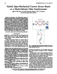
I. INTRODUCTION Current control plays an important role in power electronics converters. Among various current control techniques, current controllers implemented in dq-frame are the most well known method and widely applied in the industry and academic research [1-2]. When the current is regulated in dq-frame, it is commonly known that there exists cross-coupling between the two orthogonal dq axes. And this cross-coupling implies performance worsening, inducing slow dynamic response and interaction between dq axes. Moreover, the cross-coupling is proportional to the fundamental frequency. As a result, the current control performance will be much degraded as the fundamental frequency increases [3, 11]. Decoupling techniques are usually required to decouple the cross-coupling and improve the current transient performance. This paper mainly focuses on grid-connected voltage source converters, and their topology is shown in Fig.1(a). The ICSF method is the most common method to decouple the axes cross-coupling [2]. The inductor current is fed back and expected to counteract the plant cross-coupling terms plant. However, for digital control, there always exists nonnegligible control delay due to computation and modulation,
(a) Fig.1
The topology of grid-connected voltage source converter (a) and the PI-based current control scheme in dq-frame (b).
Affected by the control delay, the feedback current always lags the real inductor current, and therefore can’t completely counteract the cross-coupling. The cross-coupling is reduced but can not be eliminated with ICSF. Furthermore, it is proved in [4] that the ICSF will become ineffectiveness when extended to dual-sequence current controllers (DSCC) for unbalanced grid voltage conditions. Additionally, as the decoupling terms are within the control loop, the ICSF technique will affect the system loop gain and phase margin [5]. In [6], one-step prediction was implemented to deal with the control delay and improve regulation performance. The one-step predicted current instead of the sampled current was fed back as the decoupling terms. Another decoupling method, named as cVPI controller [3, 7-8], implements a complex zero in the controller to match with the plant complex pole. This method is known to have robust decoupling characteristic against parameter errors and control delay [3]. However, it is reported that cVPI controllers present a lower capability of rejecting dc disturbances (with respect to stationary frame), if the system doesn’t have enough damping and no active resistance is implemented. And in case of parameter deviations, the complex pole-zero cannot match with each other, low-amplitude oscillations of fundamental frequency may be excited [2, 8]. For cVPI controllers, it is better and necessary to implement enough damping with passive or active resistance [2].
In this paper, firstly the axes cross-coupling in dq-frame was analyzed with complex vector and complex-coefficient transfer function [7]. It simplifies the 2×2 MIMO model of three phase system into a SISO model. And the performance of the complex vector model can be analyzed with doublesided frequency response [9]. And it can be observed that the closed-loop system transfer function with good decoupling performance presents symmetry with respect to its operating frequency, e.g. 0Hz in dq-frame. The basic working principle of decoupling methods can be explained as implementing decoupling terms in the current control scheme to counteract with the plant cross-coupling terms. Both the ICSF method and cVPI controllers can be explained in this way. And a new decoupling method based on reference current feed-forward (RCFF) was first proposed. Its performance was analyzed and compared with ICSF and cVPI methods, regarding their performance under digital control delay, inductance value estimation error and so on. Experimental results were shown to verify the performance of the proposed decoupling method. II. AXES CROSS-COUPLING FOR CURRENT CONTROL IN DQFRAME
A. Modeling of grid-connected voltage source converters Fig.1(a) shows the topology of grid-connected voltage source converters. This paper mainly focuses on the current control loop. Therefore, the dc-link voltage is considered as an ideal dc source. The dynamic of the injected grid current can be modeled by (1) in dq-frame as[2, 9], G idq ( s ) =
1 G G [vdq ( s ) − vgdq ( s )] sL f + R f + jω0 L f
(1)
where Lf and Rf is the inductance and resistance of the grid and synchronous reference filter; ω0 is the grid frequency G G vdq = vd + jvq i = i + jiq frame rotating speed; dq d ; ;
G vgdq = vgd + jvgq
.
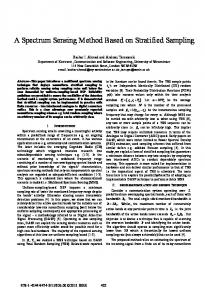
From (1), the transfer function of the grid current to the converter output voltage can be deduced as, G idq ( s ) 1 (2) P( s ) = G = vdq ( s ) sL f + R f + jω0 L f Fig.2 shows the bode diagram of P(s) with double-side frequency. The positive- and negative- frequencies correspond to positive- and negative-sequence, respectively. And the plant frequency response around 0Hz (corresponding to fundament frequency ω0 in stationary reference frame) is also clearly shown. The plant presents almost 90˚ lagging phase at 0Hz, which is significantly different from conventional dc-system. The axes cross-coupling is implied by the complex term jω0Lf in P(s). For digital control, computation and PWM modulation introduces one and a half samples control delay. The control delay has a significant effect on the system dynamic performance and stability. In αβ-frame , the control delay can be expressed by
Gd ( s ) = e − sTd
(3)
where Td =1.5Tc with Tc being the sampling period. In case of single update mode, Ts coincides with the period of the pulse modulation carrier. Due to the frequency shift property of the reference frame transformation, the delay is seen as e− ( s + jω0 )Td in dq-frame. A delay compensation term e jω 0 Td is employed to cancel the phase leg introduced by the time delay at dc. The resulting delay in dq-frame after this compensation coincides with the original one in the stationary frame. This delay compensation term provide some benefit to the current control performance, especially for current control scheme with ICSF. B. Axes cross-coupling Due to the term jω0Lf in (2), there exists cross-coupling in the current control. The bode diagram of P(s) shows a lagging phase angle (= -arctan(Lf/Rf)) at its operating frequency 0Hz in dq-frame. This lagging phase will cause negative influence on the current control if only PI controller is implemented. The ICSF is the most common employed method to decouple the axes cross-coupling. With the concept of the complex vector, the PI-based current control scheme with ICSF is shown in Fig.3(a) in a more compact way. And the closed-loop transfer function HICSF(s) can be got, expressed in either matrix form (3a) or complex transfer function form (3b). ⎡id ( s ) ⎤ ⎡ H d ( s ) − H q ( s ) ⎤ ⎡id* ( s ) ⎤ (3a) ⎢i ( s) ⎥ = ⎢ H ( s) H ( s) ⎥ ⋅ ⎢ * ⎥ d ⎣q ⎦ ⎣ q ⎦ ⎣⎢ iq ( s ) ⎦⎥ G G G idq ( s) = H ( s) ⋅ idq* ( s) = [ H d ( s) + jH q ( s)] ⋅ idq* ( s) (3b)
If the cross-coupling is completely decoupled, Hq(s) should be 0, or equivalently there should be no complex coefficient part in H(s). In this condition, the frequency response of H(s) will present symmetry with respect to 0Hz, as is shown in Fig.4 (blue line). The complex-coefficient transfer function and its bode plot provides an intuitive way to understand the cross-coupling and decoupling issue. Hq(s) can be considered as an indicator of how much cross-coupling is remained after the closed-loop control. Hq(s) shows a relationship with H(s) expressed by (4), and a function ΔH(s) can be defined as a criteria to evaluate the decoupling performance.
Fig.2
Bode diagram of plant model P(s)
ΔH ( s )
s= j 0
= H q (s) =
H ( s ) − H * ( s* ) 2j
(4)
It is not necessary to calculate out the expression of ΔH(s). The bode diagram of ΔH(s) can be directly derived from H(s) with ΔH ( jω )
0 Hz
=
H ( jω ) − H * ( − jω ) 2j
(5)
ΔH(jω)|0Hz evaluates how much symmetrical the bode diagram of H(s) is with respect to its operating frequency 0Hz.
III. DECOUPLING MEHOTDS
(6)
However, the control delay has a significant effect, especially for applications with low switching/sampling frequency. And equation (6) can not be roughly hold. The state feedback decoupling terms will significantly deviate from the cross-coupling terms. Therefore, the decoupling performance of the ICSF method will be degraded. The closed-system function with ICSF is denoted as HICSF(s) Moreover, with ICSF, the equivalent model can be considered as Peq ( s ) =
P( s) 1 ≈ e − jω0Td 1 − Gd ( s ) P ( s ) jω 0 L f sL f + R f
The control delay is modeled by Gd(z)=z-1 in discrete domain. The discrete model of the plant in dq-frame with ZOH method can be expressed as [11],
P( z ) =
A. PI controller with inductor current state feedback (ICSF) It is the most direct decoupling method that the inductor current can be fed back to counteract with the plant crosscoupling terms. Fig.3(a) shows the current control scheme with ICSF in dq-frame. The principle of ICSF decoupling technique is based on the approximation that I dq ⋅ jω 0 L f ⋅ G d ( s ) ≈ I dq ⋅ jω 0 L f
However, in [6] the one-sample predicted inductor current was fed back to decouple the system and improve stability. Idq·esTd can be roughly explained as the next-sample value, even though Td equals 1.5Ts. This prediction scheme is based on the plant discretized model with Forward Euler method. For applications with low sampling frequency, the zero-order hold (ZOH) method will show better performance [10]. Therefore, ZOH method was selected to discretize the plant model and controller here.
(7)
The plant after decoupled with ICSF can be represented as a RL load without cross-coupling and an additional phase rotation. The second term in (7) is only a rough approximation. However, it implies that the equivalent plant model contains one additional phase rotation term. This presents that the ICSF will increase the phase lag at the positive frequency side, reducing this side phase margin. It is reported that ICSF probably degrades the system stability [5]. Affected by the control delay, the resulting close-loop system transfer function HICSF(s) with Gd(s)= e− sTd shows unsymmetrical bode diagram and its gain from 0Hz to 100Hz is larger than unity, as is shown by red line in Fig.3. However, if the control delay is not considered with Gd(s)=1, HICSF(s) with shows well symmetrical as is the blue line in Fig.4.
e
jω0Ts
b − az −1
(9)
where a and b are denoted as − ( R / L )⋅T
−( R / L )⋅Ts
a = e f f , b = [1 − e f f s ] / Rf . (10) The predicted next sample current can be calculated with the following difference equation Idq [k+1] = {a ⋅ Idq [k] + b ⋅Vdq* [k −1]}⋅ e jω0Ts .
(11) The predicted next sample current is calculated with the sampled current and the last step output reference voltage. The current control block diagram with one-sample prediction is shown in Fig.3(b). The PI controller was converted to the discrete domain as PI(z) using the Tustin transform. According to Fig.3(b) and equation (11), the current closedloop transfer function can be derived as Hone-sample-pre(z)
Similar to s-domain transfer function, bode diagram of Hone-sample-pre(z) should also show symmetry with respect to 0Hz, in order to obtain expected decoupling performance. The bode plot of Hone-sample-pre(z) was drawn with a green line in Fig.7. Compared with ICSF, its bode plot shows better symmetry. However, the system response time might be slightly degraded, as the magnitude of Hone-sample-pre(z) is little lower than that of HICSF(s).
(a)
In order to conquer the negative effect of the control delay, pre-processing the sampled current with a filter F(s) before multiplied by j ω0Lf is a possible way. The ideal transfer function for F(s) would be esTd to satisfy (8), which is not physically realizable. I dq ⋅ jω 0 L f ⋅ F ( s ) ⋅ Gd ( s ) = I dq ⋅ jω 0 L f
(8)
(b) Fig.3 PI current control scheme with ICSF in dq-frame: (a) conventional ICSF; (b) ICSF with one-sample prediction
As the current prediction scheme is developed on the basis of the plant model, its performance is directly related with the accuracy of the model and parameters. Moreover, the decoupling terms are still within the control loop. Its effect to the system stability, especially with model and parameter mismatch, is not researched. It is reported in [6] that the onesample current prediction effectively solve the adverse effect of the ICSF decoupling terms to the system stability, especially under conditions with high operating frequency or low ratio of sampling frequency over operating frequency. B. cVPI controller The cVPI controller was proposed in [3,7,14], where a complex zero was implemented in the controller to cancel with the plant complex pole, as is shown in Fig.5(a). Awesome decouple performance can be provided by cVPI controllers and is not much affected by the control delay and parameter mismatch. The transfer function of the cVPI controller is given as cVPI ( s ) =
K p ( s + jω0 + R f / L f ) s
=K p +
K pω0 Ki + j . (12) s s
The control block diagram of the cVPI controller can also be redrawn as Fig.5(b), with F(s)=jKp/sLf. If Kp and Ki were set properly and the controller zero matches with the plant pole. Combining (12) and the following expressions, * ⎧⎪ I dq ( s) = H cVPI ( s) ⋅ I dq ( s) . (13) ⎨ * ⎪⎩ Edq ( s) = I dq ( s) − I dq ( s) where Edq(s) denotes the error signal between the reference current and the real current. It can be obtained that
Edq (s) ⋅ jω0 Lf ⋅ F(s) ⋅ Gd (s) = Idq (s) ⋅
jK P ω 0 s
I *dq
It was reported in [2,8] that cVPI controllers present a
Vgdq
K KP + I s
1 sLf + R f
Gd ( s) Ra
Idq
jω0 Lf
(a) jω0 Lf
F (s)
I dq*
Vgdq
Vgdq
K KP + I s
1 sLf + R f
Gd ( s )
Idq
jω0 Lf
(b) cVPI current control scheme in dq-frame
Fig.5
lower rejection capability to dc disturbances in comparison to PI controllers. In case of Lf and Rf deviations, the controller zero will mismatch with the plant pole. A low amplitude oscillations of frequency ω0 may be excited [8]. Active resistance are usually advised in order to attain a good disturbance rejection as is shown by the dashed line in Fig.5(a). But the control delay will cause instability if the active resistance becomes too large. C. PI controller with the proposed reference current feedforward (RCFF) It was mentioned in [12-13] that the reference current can be fed forward to provide some extent of decouple performance. The RCFF can provide some extent of decouple performance is based on a rough approximation that
(14)
Therefore, the decoupling principle of cVPI controllers can also be explained as they reconstruct a one-sample leading inductor current from the error signal with a filter F(s)=jKp/sLf. The two control scheme in Fig.5 is equivalent to each other. Therefore, the cVPI controller can be considered as a PI controller with error current feed-forward decoupling terms.
Plant Model
Vgdq
* I dq ⋅ jω0 L f ≈ I dq ⋅ jω0 L f
(15)
However, for applications with low current bandwidth, there will be a large error between the reference current and the real inductor current in the transient. The axes crosscoupling can not be well solved. ⎧ ⎪ * ⎪ I dq ( s ) ⋅ F ( s ) ⋅ jω0 L f ⋅ Gd ( s ) = I dq ( s ) ⋅ jω0 L f ⎪ * ⎨ I dq ( s ) = H RCFF ( s ) ⋅ I dq ( s ) ⎪ * I dq PI ( s )Gd ( s ) P ( s ) + jω0 L f F ( s )Gd ( s ) P( s ) ⎪H ( ) = = s RCFF ⎪ 1 + PI ( s )Gd ( s ) P ( s ) I dq ⎩ (16)
F (s)
jω0 Lf
*
I dq
K KP + I s
Plant Model
Vgdq
Vgdq
1 sLf + Rf
Gd ( s )
Idq
jω0 Lf
Fig.4 Bode diagram of HPI(s) and HICFF(s) with or without control delay
Fig.6
PI current control scheme in dq-frame with RCFF
H(s)
Inspired by the method in Fig4.(b) and Fig.5(b), it is possible to filter the reference current before multiplying with jω0Lf and then feeding forward to the output voltage. The filter F(s) should meet the following condition (16), where HRCFF(s) is the close-loop transfer function. If the PI controller parameter is properly set with Kp=ωcLf and Ki=ωcRf。 It can be derived finally that
Magnitude (dB)
-4 -6 -8 -10 -12 -14 -500
-400
-300
-200
-100
0
100
200
300
400
500
-400
-300
-200
-100
0 f (Hz)
100
200
300
400
500
150
(17)
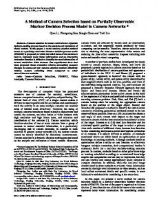
where ωc is the bandwidth of the current loop. This filter shows a typical low pass characteristics, and can be discretizd and implemented as a second order digital filter. The proposed RCFF method (Fig.6), can achieve the same decoupling performance with cVPI controllers. The bode diagram of HRCFF(s) is almost overlapped with that of HcVPI(s) in Fig.7(a). In RCFF method, the decoupling terms are pure feed-forward components, and are not within the control loop. Therefore the decoupling terms will not influence the system stability. The robustness of the PI controller can be reserved. And the parameter deviation and model inaccuracy will not cause stability issue. Moreover, the decoupling terms are coming from the reference current through a filter with low-pass characteristics. Therefore the negative influence of the current noise and sampled error can be avoided, which may be benefit to low current THD. The proposed RCFF method can be extended to dual sequence current controller for unbalanced grid voltage conditions [12]. IV. DECOUPLING PERFORMANCE COMPARISON Fig.7(a) shows the closed-loop transfer function bode plots of different current control schemes, and Fig.7(b) shows ΔH(s) of each system closed-loop transfer function. Note that the magnitude of ΔH(s) is shown in absolute value. The dashed black line in Fig.7(a) shows the bode plot of HPI(s). It presents singular variation around the operating frequency 0Hz, which results from the axes cross-coupling. This makes the bode plot of HPI(s) significantly asymmetrical, especially around the operating frequency 0Hz. And ΔHPI(s) shows the largest magnitude (>40%) around low frequency range. With ICSF, the symmetry of HICFF(s) is improved. Affected by the control delay, the axes cross-coupling is not eliminated, even though ΔHICFF(s) is almost reduced by half to 20% with the given parameters. With one-sample prediction scheme, the symmetry of Hone-sample-pre(z) is further improved. And ΔHone-sample-pre(z) is further reduced to 5%. The bode plots of cVPI controllers and the proposed RCFF method are almost overlapped with each other, and show the best symmetry. ΔHcVPI(s) is zero in the whole frequency range, while ΔHRCFF(s) still presents small value at some frequency range. It can be concluded that in terms of decouple effect, the cVPI controller and the proposed RCFF method shows same and the best performance. But strictly and theoretically, the performance of cVPI controller is slightly better than that of the proposed RCFF method. As the limited length of the paper, more comparison and analysis in terms of inductance estimation error and disturbance rejection capability will be include in a future paper.
100 Phase (deg.)
ωc s + ωc Gd (s)
0 -2
50 0 -50 -100 -150 -500
(a) 0.45 1 PI 2 PI with ICFF 3 PI with One-Sample Prediction ICFF 4 VPI 5 PI with RCFF
0.4
0.35
0.3
Magnitude (abs)
F (s) =
1 PI 2 PI with ICFF 3 PI with One-Sample Prediction ICFF 4 VPI 5 PI with RCFF
2
0.25
0.2
0.15
0.1
0.05
0 -500
-400
-300
-200
-100
0
100
200
300
400
500
f (Hz)
Fig.7 The closed-loop transfer function bode plots of different current control schemes (a) and ΔH(s) of each system closed-loop transfer functions
V. EXPERIMENT RESULTS A prototype system was experimented to verify the proposed method. As high current control bandwidth will significantly reduce the difference between these decoupling method. Therefore, the digital control cycle is the same with the switching cycle with single update mode. The simulation and experimental circuit parameters are listed as follows:1) Lf =6.18mH and Rf =0.21Ω; 2) The line-to-line grid voltage is 110V(rms); 3) DC-link voltage is 200V; 4) The switching/sampling frequencies are 2.0kHz. Current control performance with ICSF, cVPI and the proposed RCFF method were tested and compared. Fig.8 shows the q-axis current step response of pure PI current control without any decouple control. The q-axis current reference was step to 12A from 5A, while the d-axis reference was kept at 1.5A. As the q-axis current tracked the reference, the d-axis current was disturbed and deviated from its reference. The peak deviation in d-axis is 3.4A, close to 40% the q-axis step magnitude. And it takes quite a long time (almost 5 cycles) to eliminate d-axis deviation. When the decoupling methods ICSF were employed, their cross-couping between dq-axes was significantly reduced, but the d-axis still presented a deviation up to 0.9A. With onesample prediction, the cross-coupling was further reduced. Comparing Fig.8(b)~(e), the VPI controller and the proposed RCFF method provided much better decouple performance.
Note that 0.8Ω active resistance was implemental in cVPI current control scheme to depress low-frequency oscillation.
[6]
VI. CONLUSION In this paper, the current control scheme based on reference current feed-forward (RCFF) was proposed as an effective decoupling method to solve the axes cross-coupling of current control in dq-frame. Its performance were shown and compared with the other decoupling methods (ICSF and cVPI). The symmetry extent of the bode diagrams of system closed-loop transfer functions were proposed to evaluate the decoupling performance of difference method. Experimental results were shown to verify the method.
[7]
[8]
[9]
[10]
REFERENCES [1]
[2]
[3]
[4]
[5]
A. Timbus, M. Liserre, R. Teodorescu, P. Rodriguez, and F. Blaabjerg, “Evaluation of current controllers for distributed power generation systems,” IEEE Transactions on Power Electronics, vol. 24, no. 3, pp. 654–664, Mar.2009. A.G. Yepes, A. Vidal, J. Malvar, O. Lopes and J. Doval-Gandoy, “Tuning method aimed at optimized settling time and overshoot for synchronous proportional-integral current control in electric machines,” IEEE Transactions on Power Electronics,, vol. 29, no. 6, pp. 3041-3054, June. 2014. Briz, Fernando, Michael W. Degner, and Robert D. Lorenz. "Analysis and design of current regulators using complex vectors." IEEE Transactions on Industry Application, vol.36, no.3, pp 817-825, May/June 2000. A.G. Yepes, A. Vidal, O. Lopez, J. Doval-Gandoy, “Evaluation of techniques for cross-coupling decoupling between orthogonal axes in double synchronous reference frame current control”, IEEE Transactions on. Industry. Electronics, vol.61, no.7, pp.3527-3531, July 2014. J. Shen, S. Schroder, H. Stagge, R. W. De Doncker, “Precise modeling and analysis of dq-frame current controller for high power conveters with low pulse ratio,” In IEEE Energy Conversion Congress and Exposition, ECCE 2012, Raleigh, NC, USA, Sept. 15-20, 2012.
(a)
[11]
[12]
[13]
[14]
J.S Yim, S.K Sul, B.H Bae, N R. Patel and S. H, “Modified Current control schemes for high performance permanent magnet ac drives with low sampling to operation frequency ratio,” IEEE Transactions on Industry Application, vol. 45, no.2, pp.763-771, Mar/Apr 2009. J. Holtz, J. Quan, J. Pontt, J. Rodriguez, P. Newman and H. Miranda, “Design of fast and robust current regulators for high-power drives based on complex state variables,” IEEE Transactions on Industry Application, vol. 40, no. 5, pp. 1388-1397, Sep/Oct. 2004. L. Harnefors, and H.P Nee, “Model-based current control of AC machines using the internal model control method,” IEEE Transactions on Industry Application, vol.34, no.1, pp.133-141, January/February 1998. L. Harnefors, “Modeling of three-phase dynamic systems using complex transfer functions and transfer matrices”, IEEE Transactions on Industry. Electronics, vol.54, no.4,pp.2239-2248, Aug. 2007. A.G. Yepes, F.D. Freijedo, J. Doval-Gandoy, O. Lopez, J. Malvar and P. Fernandez-Comesana, “Effects of discretiztion methods on the performance of resonant controllers,” IEEE Transactions on Power Electronics, vol.25, no.7, pp. 1692-1712, July 2010. H.Kim, M.W. Degner, J.M. Guerrero, F. Briz and R.D. Lorenz, “Discrete-time current regulator design for ac machine drives,” IEEE Transactions on Industry Applications, vol.46, no.4, pp.1425-1434, July/August 2010. S. Zhou, J. Liu, L. Zhou, H. She, “Dual sequence current controller without current sequence decomposition implemented on DSRF for unbalanced grid voltage conditions,” In IEEE Energy Conversion Congress and Exposition, ECCE 2014, Pittsburgh, PA, USA, Sept. 1418, 2014: 60-67. S. Zhou, J. Liu, L. Zhou, H. She, “Cross-coupling and decoupling techniques in the current control of grid-connected voltage source converter,” In IEEE 2015 Applied Power Electronics Conference and Exposition, 2015, Charllote, NC, USA, Mar 15-19. J. Shi, J. Shen, B. Qu, H. She and Z. Tan, “High Performance complex controller for high-power converters with low-pulse ratios.” In International Conference on Power Electronics, ECCE Asia 2015, Seol, Korea, June 1-5, 2015.
(b)
(c) (d) (e) Fig.8 Experimental results with (a) PI without any decouple control; (b) PI with ICSF; (c) PI with one sample predicted ICSF; (d) cVPI with Ra=0.8; (e) PI with proposed RCFF