Video Localization Using Array of Microphones Yasir Salih1, Patrick Sebastian 2, Yap Vooi Voon3 1,2
Electrical and Electronics Engineering Programme Univrsiti Teknologi PETRONAS, Bandar Seri Iskandar, 31750 Tronoh, Perak, Malaysia Tel: +60-5-3687851, Fax: +60-5-365-7443, Email:
[email protected] 3
Department of Electronic Engineering Universiti Tunku Abdul Rahman,Perak, Malaysia Email:
[email protected]
Abstract: This paper discusses the development of a video localization system to be used as an automatic cameraman in interactive video discussions to eliminate the need for camera operators.The system consists of microphones, multiplexing circuit, computer and PT camera. The localization algorithm is based on comparing the amplitude level of the signals from all microphones and then selects the one with higher amplitude, strong noise presence is one of the limitations of this techniques, however the type of noise added can be clearly identified and removed in the frequency spectrum,and based on the results obtained the PT camera can be localized to cover the desired area. Initial results shows clearly demonstrate that this techniques is usable for video surveillance. The system is been developed for closed room localization but it can also be extended to outdoor applications by using suitable sensors and suitable cameras, in video discussions the system can be used in conferences and in parliament halls where such a system can be used as an automatic cameraman.
Keywords Camera localization, signal processing, USB protocol, PT camera.
Introduction In videoconferencing application human controlled cameras are located in different location to track active speaker when they participate in the discussion[1]; such a system uses a professional camera operators whom are highly paid and it is very tedious work as sometimes it is difficult for the operator to locate where the speaker is within the hall. Reducing this costly process can be achieved by using automated video localization system that depends on array of microphones allocated in front of the speaker and a steerable camera allocated in the middle of the conference room in order to cover the whole room; such a system is capable of locating the active speaker in 3D- space and therefore; it eliminate the needs of professional camera operators andneed for multiple
cameras, and this results in reducing the total cost involve and makes the system more accurate[10]. This paper discusses the steps taken in developing audio based camera localization. Section 2 discusses the system components and how each part is being handled as well as the integration of these components into a complete system. Section 3 discusses the experimental result been drown during the experiments conducted, section 4, discusses the result and the system performance and section 5 conclude the study and discuss the possible future enhancements on the project.
Approach and methods This section discusses the components of the system and he methods used in each part and it also describes how the system is been integrated. System description The proposed system consists of four directional microphones and a PT camera; the microphones works as sensors to detect the active speaker taken into account that speech is a measure of activeness. In addition to that there is computer to work as the system process and to display the results and a multiplexing circuit to collect the audio data from different microphones at fed it to the computer at different timing.
Figure 1: Localization system.
Camera localization using audio clue consists of two major parts; audio processingpart and video visualization part, the audio is about how audio signal is captured, process to reach a decision of which microphone has an active speaker. The video part is about how camera is steered to the speaker location and how images been displayed. Audio processing system
isconnected to the computer. The microcontroller is used to issue the multiplexer control signals at a specified periods, the microcontroller used is the Microchip PIC18f4550 and it is capable of communicate with a host device through a USB link[5], the USB link provides the required synchronization for the system to avoid data overlapping or data misplacement. Figure 3 shows the complete circuit diagram for the multiplexing system.
Audio sensors are microphones, four microphone are used this study, there is no amplification stage and the audio data is directly linked to the computer. Normal computer has one sound card and can accommodate one audio input; therefore to accommodate all these sources into one computer a multiplexing technique is used and all the microphone are connected to a multiplexer which connect to the computer. Multiplexer allows the microphones data to be fed sequentially to the computer based on predetermined sequence or via instructions given by the computer. At the computer side the received signal is de-multiplexed to reconstruct the original signals; hence it is very essential to synchronize the multiplexing and the de-multiplexing process so the computer can able to reconstruct the correct signals. Figure 2 demonstrates a block diagram of audio multiplexing de-multiplexing system; the left blocks are external circuitry while the right blocks are inside the computer.
Figure 2: algorithm of capturing audio from multiple sources. The synchronization ensures that the data coming from one microphone is allocated at the same microphone during the de-multiplexing stage; synchronization system is a communication link between the multiplexer and the demultiplexer. i.
External circuit:
External circuits are used to perform the multiplexing before the audio data is fed to the computer audio input jack. The circuits consists of analog multiplexer and PIC microcontroller, the analog multiplexer is the CD4097 [2]dual channel multiplexer, its capable of undertaking up to eight input at each channel, the multiplexer is control by three control signals (C0,C1 and C2). The microphones are connected to the multiplexer as inputs and its output signal
Figure 3: circuit diagram for the multiplexing circuit. ii.
Operation principle of the external circuits
At first the computer request form the microcontroller to connect a specific microphone by sending its ID through the USB link, the microcontroller has a lookup table contains the appropriate control signals for each microphone as shown in table 1, based on the given control signal the multiplexer will connect the desired microphone and disable all the others, finally after considering the propagation delay time the computer will receive the audio data and allocate it for the specific microphone. Table 1: decoding the received control signal from the computer at the microcontroller[2]. Microphone ID number Multiplexer control signals A B C 1 1 1 1 2 1 0 3 1 0 1 4 1 0 0 Due to the propagation delay time the multiplexing rate cannot exceed maximum threshold to avoid signal overlapping, the propagation delay caused by the time taken by the computer to issue the multiplexing signal, the USB propagation time, the time taken by the microcontroller to decode the microphone ID and put the control signals on the multiplexer control pins, the time taken by the multiplexer to connect the desired microphone and finally the time taken by the computer to receive the header of the new data.
The computer receives the input data of all microphones as if it is coming from a single audio source; then it demultiplexes or resample the original four audio sources, the computer reconstruct four waveforms form the given one based on a known time sequencing, the data is received in a form of audio frames each frame contains 8912 samples and the sampling rate is 192000 sample/second which means there is 23 frame/second, table 2 shows all the predefined setting for the received data, all these values can be modified by the user even during the run time of the program[3]. Table 2: Predefined settings for microphones data. Attribute Value Sampling rate 192000 samples/second Samples per frame 4096 samples of 16 bit samples Frame rate 23 frame per second Maximum allowed frequency 10KHz Minimum allowed frequency 50Hz Bits per sample 16 bits Number of audio channels 1 Multiplexing rate 250 milliseconds Propagation delay 50 milliseconds
level but the frequency lower than 300 Hz is very much affected by noise, therefore it is easier to consider it as noise and avoid the need for extra filtering process. For the higher limit which is at 6.0 KHz human speech, beside frequency filtering a threshold is imposed on the audio signal that should be fulfilled, the threshold will help removing the white noise that presents on all frequencies. The threshold level can be selected by the user based on the signal to noise ratio the lower the signal to noise ratio is the higher the threshold value is.
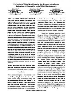
Figure 4: Selecting the desired frequency range.
Figure 5 shows the flow of multiplexing program.It starts by issuing a multiplexing signal to the PIC through the USB communication link, the signal contains the ID of the microphone that should be connected. Since there is going to be a propagation delay from the time the multiplexing signal is issued until the audio data arrives; any data comes during this time is considered for the preceding microphone. After the propagation delay period is completed the program receives the data and allocates it to the intended microphone. Next the data is fed through a filtering process as shown in the flow chart of figure 6. The time domain filter is intended to remove the impulse noise that propagate due to the switching effect. Impulse usually has very high amplitude and short duration[16]; this is the property used to detect it. The role of the frequency domain filter is to suppress all unwanted frequencies which are defined by the user as Table 2 illustrates; since the project is dealing with merely human speech the minimum frequency and the maximum frequency are set to be the boundaries of the human speech range of frequencies as in Table 2. Finally the system compare waveforms based on their amplitude level and select the one with highest amplitude as the desired one; the comparison is done in the frequency domain because it is easier to distinguish and remove the noise in frequency domain rather than in time domain. When comparing the frequency spectrum of signals with each other not the entire spectrum is used but rather a narrow range that represents human speech is compared in order to eliminate noise presence, Figure 4 shows the selected frequency of interest. The minimum frequency is selected at 300 Hz although there is some human speeches bellow this
Figure 5: flow diagram for audio processing at the computer. In this work the camera used is an IP camera that can be accessed both through LAN cable as well as wirelessly. In order to be able to use any IP device it has to be connected to a network[6].
The camera retrieve images in JPEG format [4],open source codes provided by codeproject website [4] had been used to access the camera and retrieve the JEPG images. Steering the PT camera requires the use of URL special commands[5], these commands are used to perform panning tilting and digital zooming operations. These commands are specified by the camera manufacturer
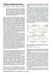
Results and discussions The results obtained show that the localization system the audio data can be detected by any microphone location and its amplitude. The camera issteer to the microphone location and tag that microphone as an active microphone. In Figure 6the upper side shows the frequency spectrum of onemicrophone.The lower part of the window shows the image the desired output of the system. In addition it shows the selected microphone and the amplitude counter as well as the camera pointing location in a text format.
Camera steering is achieved by sending URL commands, these commands contains the direction and the speed of the motion, the speed of the motion determine whether the camera reach the destination faster or slower, that make the destination for one URL command fixed despite the motion speed. However when steering the camera sometimes user requires the camera to steer to a far distance or sometime to a near one, thus it is necessary to use multiple URL call if one URL call is not enough to reach to the desired destination.
Conclusions The initial results showthat a camera can be localized using audio sensors in an indoor environment. Microphones are good sensors for videoconferencing application because it can sense the present of audio data. For outdoor applications microphones are not a reliable sensors because of the presence of very strong noise that leads to a week signal to noise ratio (SNR < 1). The audio processing system successfully suppress some of the noise and interference present due to the multiplexing, a band pass filter is used to removes frequency components outside the band the desired range. The camera used in this work is suitable for small area surveillance, however its pan and tilt operations are nonlinear and it does not support optical zooming which is necessary for large area surveillance.
Acknowledgement This project is developed in the electrical and electronics engineering department, Universiti Teknologi PETRONAS.
References Figure 6: Localization results shown for MIC 1.
Discussions The multiplexing circuit adds noise to the system, the type of noise added is not a regular impulse noise, but it rather has a longer discharge time which makes it difficult to be removed in a normal ways, however in the frequency spectrum this noise appear as a low frequency component; therefore low pass filter can help removing it. The chosen multiplexing frequency is set to be 0.5 Hz this is the optimum multiplexing rate to avoid signal overlap between the microphones, although this rate conflict with Nyquist criterion for sampling which says that the lowest sampling rate must be larger than twice the maximum frequency [6]which mean is shown be > 20KHz (assume max frequency is 10KHz). However this rate is still acceptable because the audio average amplitude level is the point of interest not the exact meaning of audio data. Increasing the multiplexing rate bend 0.5 Hz will result in increase in impulses and distortion of the signal.
[1]. B. R. Abidi, N. R. Aragam, and others, December 2008, Survey and Analysis of Multimodal Sensor Planning and Integration for Wide Area Surveillance, university of Tennessee, ACM computing survey. [2]. CD 4097 dual channel analog multiplexer/ demultiplexer datasheets. [3]. Jeff Morton, Sound Activated Recorder with Spectrogram in C#, code project website http://www.codeproject.com/KB/audiovideo/SoundCatcher.aspx, last visit 24/10/09. [4]. Andrew Kirillov, Camera Vision - video surveillance on C#, code project website http://www.codeproject.com/KB/audiovideo/cameraviewer.aspx, last visit 24/10/2009. [5]. USB serial Board on 18F4550, Microchipc website http://www.microchipc.com/sourcecode/index.php#pic1 8f4550usb, last visit 24/10/2009. [6]. Sanjit K. Mitra, Digital signal processing a computerbased approach, 3rd Edition Mac Graw-Hill.