Abstract: _It is known that speed control on the universal motor by means of microprocessors is very complex and expensive. However, the speed control ...
Proceedings of the 6th WSEAS/IASME Int. Conf. on Electric Power Systems, High Voltages, Electric Machines, Tenerife, Spain, December 16-18, 2006
A Digital Speed Control Application on the Universal Motor with PIC Microcontroller YASAR BIRBIR Technical Education Faculty, Electrical Department Marmara University, Goztepe-Istanbul Zip code.34722 Phone 90- 0216-3365770; Fax:90-0216 337 89 87 TURKEY MUSA YILMAZ Vocational Higher School, Electrical Program Dicle University, Siirt Zip code.21280 Phone 90-0484-2232643; Fax: 90-0484 224 36 92 TURKEY Abstract: _It is known that speed control on the universal motor by means of microprocessors is very complex and expensive. However, the speed control application on universal motor by peripheral interface controller (PIC) may be done with more simple hardware and software program. Generally, the microcontrollers are preferred because of their capability to find solutions for all kinds of control problems that couldn’t be solved by the microprocessors. Hence, they have been developed rapidly and used in various fields recently. Also due to superior capabilities of the PIC, they are preferred on the universal motor speed control. Usually, two different methods have been used on the universal motor speed controls; one is period measuring and the other is frequency measuring. In this study, both methods were applied on the universal motor speed control. The triggering angles of the triac were changed with feedback received from the tachogenerator that was coupled to the universal motor shaft and the speed of the universal motor was ensured to remain stable under the variable load. The working principle of the program and the written text of the program were presented in this study. In addition to the application results, the suggestions on the advantages and development of with microcontroller system have been made. In conclusion, it was found that this application may be more secure speed control method than the others. Key-Words: _ Didital Speed Control, PIC Microcontroller, Feedback, Universal Motor, Open Loop.
1 Introduction Modulation techniques are very hard to be carried out with analog circuits. However these techniques can be done more effectively with optimal control methods based on microprocessors or microcontrollers [1]. Digital speed control is commonly used in industrial driver systems. Also, stable speed control gives the working region with a stable moment under the nominal frequency. Open loop method without feedback is preferred for better dinamic performance in standart applications. Speed adjustment on the control of motor speed with the open-loop system could be done by changing the voltage on the armature or exciting winding. The changes on the motor voltage and the value of motor speed in the open-loop system aren’t taken into the consideration. In this method, the speed
might be increased or decreased in accordance with the change of load. Hence, open-loop system must not used in stable-speed. In this study, the magnitude of the output voltage was made independent from system variables in motor speed control with closed loop system. Therefore, value of feedback controlled motor speed has to be fixed with closed loop [2]. The number of motor turn in the closed-loop circuit is adjusted by reference value. With the help of tachogenerator used in the system, changes in the motor speed are sensed. According to the load change of the motor, the motor speed number is kept at the reference value by changing the voltage on the armature or exciting winding [3]. As the motor voltage is adjusted by semi-conductors, the system is efficient and reliable. An error signal occurred in the system is evaluated on the controller and then it is transferred to the output. The error
126
Proceedings of the 6th WSEAS/IASME Int. Conf. on Electric Power Systems, High Voltages, Electric Machines, Tenerife, Spain, December 16-18, 2006
signal is multiplied by system gain and the integral of the error signal is taken. Proportional integral (PI) output is either increased or decreased according to the value of the error signal [4].
2 Digital Speed Control Module The software is a program that was written in the assembler language for the PIC. In this study the speed control module (SCM) was designed by using 16F73 -Micro CHIP for induction motors of the automatic washing machines [5]. Software was used to do PI speed control, unstable load test and blocked rotor test. The speed of the washing-machine was adjusted by input voltage variation made on motor windings. The voltage was adjusted by regulating the triggering of triacs connected to the microcontroller output. Tolerations for speed are 20 revolutions per minute (rpm) in squeezing cycle and 1.5 rpm in washing cycle. The main function of speed control module was to run the tambour of the washing machine in the desirable speed [6]. However, speed of the machine can not fix in the event of feeded by stable voltage because sudden conditions of laundry and water changes coupled load quantity. In order to keep stable the speed of the machine in desirable level, the speed of the machine was feed-backed to the SCM. When the speed of the machine decreased below the desirable level, applied voltage should be increased by using feed-back, in other words triggering angle should be decreased. Similarly, if the speed of machine was increased the desirable level, voltage applied on motor should be decreased in other words the triggering angle should be increased [7]. Algoritma which provides controlling of speed by changing triggering alpha (α) angle on appropriate level controls PI in the software. In this control method, the data of speed feed-back taken in every sampling time was compared with reference level. The difference between them was regarded as error and processing of this error in a suitable way, new triggering (α) angle was found. Carried processes will be explained in detail in control routine section. The data of the speed feedback were sinusoidal voltages taken from tachogenerator which has been coupled to the motor. Output voltage of tachogenerator which was cut off positive cycle and inverted negative cycle is a square wave shape appearance, this voltage was applied to the inputs of microcontroller by hardware. The program measured the period of the voltage in the slow running washing cycle by using the real
time clock counter (RTCC) in internal mode and calculated error in the speed by using error = reference - period formula. However, in the high speed running squeezing cycle, it measured the frequency of the same voltage by using RTCC in external and the error in the speed was calculated with “error = frequency - reference” formula. The program used period measurement method for unstable load test. It will be described later in detail in the unstable load section. It was useful to give a short summary to explain measurement and assessment’s integration to the software. Occurrence of unstable isaccumulation of laundries to the only one part of machine and this causes forcing of motor. The tachogenerator sends 128 periods to the microcontroller for complete turning of machine vessel. In unstable turning, laundries which were piled in only one part of vessel cause slow turning during ascend of vessel and it is opposite during descend of vessel. Consequently, some periods measured in a complete turn are lower than reference value but some periods are higher than this value and these are called as ‘period errors’ [8]. Unstable load quantity was determined as a result of the total absolute worth of period errors measured at 1000 period with the comparison of known unstable load period error reference. For instance 1500 g balance which was the load period error reference value of d3488, was saved in ‘hb1500, Ib500’ memories, the worth of 900 g unstable load period reference the number of d’2278’ which was was saved in ‘hb900, Ib900’ memories [9]. Unstable load measurement has been done at 100 rpm, because that speed was such a slowly speed not to damage the washing machine and as high as unbalanced load can guarantee that laundry is sticked to the vessel with centrifugal force.
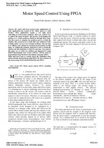
3 Running of the Program Program followed flow cart as seen in Fig.1. At the beginning of the program, the machine type was read by determining with jumpers connected to PIC’s RC6 and RC7 inputs. While the washing machine was in its squeezing cycle, it reached its maximum speed in five steps. Reference levels for these speed steps, different for each machine type, were lined sequentially on a table labeled with “sktb”l in the program. The offset value defined from table was determined by determination of machine type. Determination of offset was formularized with“offset= 5x(machine type)” correlation[10].
127
Proceedings of the 6th WSEAS/IASME Int. Conf. on Electric Power Systems, High Voltages, Electric Machines, Tenerife, Spain, December 16-18, 2006
START
Prepare for smooth rising
Synchronization
NO
The part of periot measurement
YES
Is it squeezing?
Set into action as a shape of quartet consecutive blows at ignition angle
Set into action 960 µs at ignition angle 50 ms
NO
The parth of Frequency measurement
110 ms
Illustration time?
NO Illustration time?
YES YES
Is it 52 rpm ?
YES
NO (100 RPM)
The set up of squeezing steps, velocity control and motor block test Velocity control and motor block test
Velocity control and motor block test
The measuring of unstable burden
To observe
NO
Unstable 1500 gr? YES Work 52sn make 100 revolution set up
Obstruct setting into action and make pre-set up for washing
STOP
Make set up of squeezing1 or squeezing2
SQUEEZING At which situation?
NO Is it 100 rpm?
WASHING Make washing set up
YES Make 100 rpm set up
Fig.1 Flow chart of speed control module
128
Proceedings of the 6th WSEAS/IASME Int. Conf. on Electric Power Systems, High Voltages, Electric Machines, Tenerife, Spain, December 16-18, 2006
Determined offset appointed to “machtype” saver. For squeezing, real squeezing speed reference that must be applied was determined with the adding of speed reference sign named ‘refptr’ saver to this offset (Refptr can be five as maximum). When machine type was read as three (3) from RC6 and RC7 inputs, offset was appointed to “machtype” saver as 5x3=15. This means that the speed reference value at 1005 rpm was become offset. When “refptr” was assumed to be 2, the reference level which was to be carried out for squeezing was at 450 rpm. The increase of ‘Refptr’ and adding to offset processes occur in checking routine [11]. After the machine type and the offset speed were determined, input-output ports were introduced to microcontroller and their first values were appointed to some savers. In the following process, the triac triggering angle was appointed to a big value (114 degree) to provide the motor to be speeding up slowly before reaching the demanded turn in motor washing program. The machine running with this triggering angle reached the demanded speed with the PI control in the control routine when it reached adjusted angle level. Synchronization operation of block diagram was given at the previous page. As it is understood from the flow chart in Fig.1, when there was a change in the RBO input of synchronization (when the network voltage crosses from zero), synchronization operation ends. On the opposite situation, rotation continues. When flow chart in Fig.2 is followed, the current stage is the operation of synchronization reached from program’s different positions (It is explained with ‘lp’ label in the program). This operation means that the program follows the network voltage and occurs with the determining of the zero network voltage crossing. Determining of the zero crossing was done by output value belong to the synchronization with its previous value done EXOR.
Variables were used in the flow cart. old
: Old values of syncronization inputs
new
: New values of syncronization inputs
w
: Result of the : ‘new x or old’ proceses
temp : Temporary variables
Fig.2 Synchronization flow chart With regarding the probability of entering to the endless rotation in any process of the program, PIC’s watch dog timer (WDT) feature was used. If, WDT wasn’t reached until 18ms, PIC clears itself. When the synchronization operation was finished, WDT cleared and according to this voltage, the washing machine it continued to frequency or period measuring section.
129
Proceedings of the 6th WSEAS/IASME Int. Conf. on Electric Power Systems, High Voltages, Electric Machines, Tenerife, Spain, December 16-18, 2006
Fig.3 The period measurement flow chart
130
Proceedings of the 6th WSEAS/IASME Int. Conf. on Electric Power Systems, High Voltages, Electric Machines, Tenerife, Spain, December 16-18, 2006
4 Measurement Although normal washing occurs in 52 rpm, unstable load test squeezing occurs in 100 rpm. It was indicated in the program with the “pertype” label. The period of 10 ms section at the end of the synchronization prior to zero crossing is waited until trigger angle after it is appointed to “per 50” savers. If the trigger angle of triac, come first time, it is the soft raising degree determined at the beginning. If it is not come the first time trigger angle is an angle that determined at the control routine Fig3. When trigger time was reached, RA2 and RA5 inputs drive triac gate turn into active high position. The first output transformed into high position at the same time is to share input current. Trigger pulse continued “firetmr” routine in 960 microseconds. In the waiting time of trigger angle and until the trigger pulse come to off period evaluation, routine run continuously. These processes are repeated after each zero crossing when sampling time is reached [12].
4.1 The Period Measurement Routine The period measurement in the software of the digital speed control; 1. Speed control for 52 rpm and 100 rpm as a feedback, 2. It is needed determination of unstable load after squeezing test in the 100 rpm. During the synchronization, period measurement routine labeled as “permeas” is called both while waiting trigger angle in the period measurement section and in the time when trigger continous. The feedback signal comes from tachogenerator is sended test to PIC’s RC2 input slot for a period measurement. The signal which comes from the tachogenerator was a sinusoidal signal. Hardware transforms that voltage into a pulse voltage form. If the time can be measured between two pulses which comes back to back, this means that period is measured. When period measurement routine was called, firstly it was checked for wheather or not program was on squeezing period. At the squeezing, routine ends before measurement. If it is on the
washing section, the period measurement starts. Firstly the presence of pulse is examined. Therefore, the possibility of a change in RC2 slot was inspected. “newp” (the value of RC2 input) and “oldp” (accepted as zero at the beginning) are processed by EXOR and the results are evaluated. If there was a difference in both input values, it was inspected that whether or not this difference are from logic 0 to 1. If the difference is not on the rising edge, the last logic level determined is transferred to the “oldp” and it is run out of routine to detect the further change. On the other hand, if the change is determined on the rising edge, it is analysed for electro magnetic interference (EMI). For this examination, 90 microseconds are waited and at the end of this time if input value is logic 1, there is no EMI. If there is no EMI, the presence of first raising edge is controlled in the 50 ms time section of sampling. If it is first raising edge, the time wich was occurred after network voltage zero crossing is appointed to “oldt” and it is run out of routine by determining of 10 ms section. Time of the pulse after the second raising edge (zero crossing distance) was hidden in “newt” and it is detected that the “newt” is in which 10 ms division of time section. Input pulses in which 10 ms division is placed is detected with counter memory. Counter is a device that it is cleared in sampling time and increasing per 10 ms. When a new pulse comes, counter index was taken to “newsay” memory. If “oldsay” content showing the time section of the previous pulse is the same with the “newsay”, pulses are in the same time division. If the difference between them is logic 1, pulses are in the sequential time division. The measured period may be as high as 10 ms because of the limited memory in the microcontroller. If it is measured higher than this value, there should be wrong measurement, and period is limited with10 ms. All speeds below 45 rpm are detected as 45 rpm and this does not prevent the process of speed fixing in the 52 rpm and 100 rpm. If maximum period comes continuosly, blockage condition occurs and it stops.
131
Proceedings of the 6th WSEAS/IASME Int. Conf. on Electric Power Systems, High Voltages, Electric Machines, Tenerife, Spain, December 16-18, 2006
Fig.4 The frequency measurement flow chart
132
Proceedings of the 6th WSEAS/IASME Int. Conf. on Electric Power Systems, High Voltages, Electric Machines, Tenerife, Spain, December 16-18, 2006
4.2 The Frequency Measurement Routine In this part, when the washing machine was in squeezing position which was needed for the PI speed control frequency of the signal which comes from the tachogenerator is measured and different from the period measurement part, the triac trigger process was done with four times in sequential pulses. The signal which was sent from tachogenerator to the SCM, amplitude and the frequency vary with caldron speed that is sinusoidal voltage. The Hardware in the SCM converts this signal to squarewave wich it’s negative phase inverted and positive phase is cleared. SCM software, in a certain time (100ms) by counting the pulses which were coming to real time clock counter (RTCC) inputs of microcontroller as shown in Fig.4. Hence, measured frequency was not counted number of pulses in a second. But, as the reference value used with the frequency that measured in control routine was also (pulse / 100ms), no unit mistake was made in calculations [13]. Before reaching to the frequency measurement section, the adjustments have been made in “follow” routine for the inputs of RTCC. According this by using “option register” RTCC “external” is connected and in rising pulse ‘prescaler’ 2 is adjusted by rising one value of “RTCC” memory. It could be understood by looking in to the “RTCC” memory detail how many pulses came in 100ms time
5 Conclusion The digital speed control of universal motors of washing machines may be done by various methods. Although the speed control is done by phase shifting in practice, in new technologies the speed control is done by computers, microcontrollers or microprocessors. The PICs stand out first row in this field. Also, it is preferred due to its easy usage and low cost. Complete and reliable control of speed can not be done in a result of phase shifting with a certain angle by the phase shifting circuits. Therefore, digital speed control is both secure and economic systems. In this present study we concluded that digital speed control is more sensitive and secure. In addition to speed control circuit of universal motor continuity and
reliability of control is enhanced by a feed-back done from a tachogenerator. In conclusion, this method provides more secure control than the other control systems.
References: [1] Kuo, B.C., “Automatic Control Systems” Sixth Edition, 1990 Prentice Hall. Englewood Cliffs, New Jersey 07632 ISBN 0-13-0510546-7. [2] Fitzgerald, A.E., Kinglesley. C., Kusko.A. “Electric Machinery” McGraw-Hill Book Company 1991. [3] Paul, H., Winfield H. “The Art of Electronics” Cambridge University Pres., Sixth Editon, 1992.ISBN 0-521-37095-7. [4] Ogata, K., “Modern Control Engineering” Second Edition, 1991, Prentice Hall. Englewood Cliffs, New Jersey 07632 ISBN 0-13-589128-0. [5] Tocci, R. J., “Digital Systems Principles and Applications.” Fifth Edition, 1993, Prentice Hall. Englewood Cliffs, New Jersey 07632 [6] Charles, L., Phillips. H., Nagle, T., “Digital Control System Analysis and Design” Thirth Edition, 2000, Prentice Hall. Englewood Cliffs, New Jersey 07632 ISBN 0-13-213596-5. [7] Bose, B.K., “Modern Power Electronis and AC Drives,”2002, Prentice Hall, Inc. Upper Saddle River, New Jersey 07458 ISBN 013-016743-6. [8] Kleitz, W., “Microprocessor and Microcontroller Fundamentelas”, The 8085 and 8051 hardware and” Software, Prentice Hall, 2003. [9] Treibel, W.A., “Microprocessor Hardware, Software, and Interfacing” Prentice Hall 2004. [10] www.microchip.com.Technical Library Fifth Edition, (Febr. 2005). [11] Smith, D.W., “PIC In Practice” Amazon.com. (May.2005). [12] Clark, D., “Programming and Costimizing the PIC Microcontroller” Amazon.com. (June.20.2006) [13]Hellebuyck,”C“Programming PIC Microcontrollers with Pic Basic”, Elproducts, Chuck Inc., Nuts and Volts Magazine, U.S.A. ISBN: 1-58995-001-1, 317 pages, publication date: 2006 Imprint: NEWNE
133