Abstract - In this paper, universal motor speed control system with a PWM AC chopper is introduced. Operation principles of the control system, which is realized ...
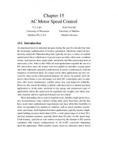
Universal Motor Speed Control with Current Controlled PWM AC Chopperby using a Microcontroller Hac1 Bodur, A. Faruk Bakan,M. Hadi Sarul Yildiz Technical University, Dept. of Electrical Engineering Istanbul 80750, TURKEY
-
Abstract In this paper, universal motor speed control system with a PWM AC chopper is introduced. Operation principles of the control system, which is realized with a microcontroller, are presented. Mathematical model of the universal motor and PWM AC chopper is derived and the behavior of the system is studied by simulation. Mains power factor, motor speed, and current are analyzed for different load conditions. Harmonic analysis of the motor current and voltage are given and compared with phase control technique. Experiments are made to verify the effectiveness of the system. According to the experimental results, both simple hardware design and good speed response can be attained.
II. OPERATION PRINCIPLE AND ANALYSIS The universal motor speed control system with current controlled PWM AC chopper is shown in Fig.1. In the system voltage equation of universal motor can be written
as,
where the field and armature currents are related by the following equation,
I. INTRODUCTION
Universal motors are widely used in household appliances like food processors, vacuum cleaners, sewing machines and most domestic appliances because it is cost effective in respect of volume/power and it has a good torque response. In the control of these motors, generally, providing stable speed control, preventing large cuirents and drawing minimum harmonic current from ac mains supply are required. To meet these requirements using AC chopper with current and speed feedback is preferred. In addition, a control system with low cost is desired [1,3,4].
AC choppers
rms value of AC voltage feeding a load fiom a constant voltage AC source are in that change the
widespread use for purposes of power control in industrial applications such as-heating, lightning and ac motor speed control. For many years, AC power control has been done economically and simply up to very high powers using the phase control technique with naturally commutated ac chopper circuits made up of thyristors and triacs. In this form of power control it is known that depending on phase control angle, the load voltage harmonics increase, interruptions occur in load current and the ac mains power factor reduces [2,5,6]. In this work, universal motor speed control system with PWM AC chopper is simulated and the system has been realized by using a microcontroller. In the system, AC mains power factor, motor speed, and current is analyzed, simulation are compared with phase control technique.
The voltages across the windings are related by,
(3)
By using (2) and (3) voltage equation can be rewritten as
-
V(t) = [R + Lp Mo]i(t) where R=R, +Rf L=L, + L f . The mechanical equation can be written as dw dt
T, =TL+ J-+Do
= i,.M.if = K,.ii.
(7)
AC mains power factor is given as
where I is the rms value of supply current, 11 is fundamental component of I and cp1 is phase angle of I. Displacement factor of the input current is given as Dis.F. = cos cpl .
0-7803-5812-0/00/$10.00~2000IEEE
(4)
394
(9)
I .
I
I
Synch. nrd
.b
MI
1.
c
I
I
control and Drive Circuit *
n
I
1
No
Fig. 1. Universal motor speed control system with cunent controlled P W M AC chopper.
Fig.2. Control block diagram of the system. Control system block diagram is given in Fig.2. In the diagram, according to speed error e between the desired speed n,ef and the real speed n, PID controller produces sinusoidal reference current, which is in the same phase with AC mains voltage. Hysteresis current controller provides the motor current to follow the reference current in a selected hysteresis IH band according to difference between reference current iref and motor current i,. Reference current is given as,
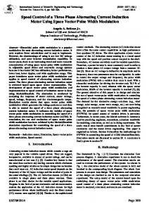
Simulation of the system is realized by using MATLAB. The psuameters of the universal motor used in the simulations are given in Table 1. Variations of the motor voltage, current, and their harmonics obtained from the simulaticin program for P W M AC chopper and phase control technique is given in Fig.1 for comparison. It is clear that the proposed system is superior to phase control technique in respect of power factor.
F F ] Table 1. Parameters of the universal motor.
i,, = I,,,,sinot
, 0 e I,,,, e I,,
.
(10)
Reference current is automatically changed between zero and nominal motor current in order to obtain the desired speed. If the motor current falls below absolutely IW2 than reference current then MOSFET M2 is"tumed off and M1 is turned on, so AC mains voltage is given to motor. Similarly, if the motor current exceeds reference current absolutely M/2, MOSFET M1 is turned off and motor voltage is made zero with the conduction of M2. By using optical interlocks with isolation in the drive circuits, MOSFETs are prevented fkom conducting at the same time together. 395
220 v
For the simulations shown in Fig. 1, 1/4 of nominal voltage is obtained at motor terminals by selecting proper reference current Irehin the current controlled P W M AC chopper and a in the phase control. From the analysis of Fig.]. with simulation program, Disp.F. and PF values are calculated as 0.95 and 0.49 for P W M AC chopper, 0.34 and 0.28 for phase control respectively.
, Motor voltage (v)
0
0.01
0.02 Motor current (A)
0
0.01 0.02 AC mains current(A)
Motor voltage harmonics(V)
. . . . . . . . . . . . .
0.03
0.04
1
3
5 7 9 11 13 15 17 19 21 Motor current harmonics(A)
0.03
0.04
1
3 5 7 9 I 1 13 15 17 19 21 AC mains current harmonics(A) .
.
.
.
.
.
.
5
7
9
11 13 15 n
.
-
I
0.5
0 0.5 0
0.01
0.02
0.03
0.04
1
3
t (6)
Motor voltage (V)
17 19 21
Motor voltage harmonics (V)
"
0
0.01
0.02
0.03
0.04
"
Motor current, AC mains current (A)
0
0.01
0.02 t (s)
0.03
1
3
5
7
9
I 1 13 15
17-19
21
Motor current, AC mains current harmonics (A)
0.04
1
.
.
.
.
3
5
7
9
.
.
11 13 n
.
.
.
15 17 I 9 21
(b)
Fig.3. Universal motor voltage, current and AC mains current variations and their harmonics for the fundamental value of motor voltage V = 1/4.Vn, a) in the PWM AC chopper circuit, b) in the AC chopper with phase control technique.
396
Motor voltage 01)
Motor voltage harmonics(V) I
0
0.01
0.02
.
. .
.
0.02 AC mains current(A)
0.01
.
-
. .
-
. I
0.03
0.04
1
3
0.03
0.04
1
3 5 7 9 11 13 15 17 19 21 AC mains current harmonics(A)
1
3
5 7 9 11 13 15 17 19 21 Motor current hamnics(A)
Motor current (A)
0
'
2 1
;
0
:
!
.
o0
-1 -2
0
0.01
0.02 t (8)
0.03
0.04
5
7
9
I 1 13
15
17 19 21
15
17 I 9 21
n
Motor voltage 01) 200 0
-200 0
0.01
0.02
0.03
0.04
')
1
I C .
0
0.01
0.02
3
5
7
9
11 13
Motor current harmonics(A)
Motor current (A)
0.03
. . . .
.
. .
. .
- 4
0.04 AC mains current harmonics(A)
AC mains cwrent(A)
1
1
0 -1
0
0.01
0.02 t
0.03
1
0.04
(a
3
5
7
9
I 1 13
15
17 19 21
n
(b) Fig.4. Universal motor voltage, current and AC mains current and their harmonics for the PWM AC chopper circuit for fundamental value of the motor voltage, a) V ==3/4.V,, and, b) V = 1/2.V, .
3 97
’t O‘O
t
O‘Ot 0.4
O2
t
-
4
/’
/
I
‘0
1
I 0.5
1
1.5
2 lnhn
2.5
3
3.5
4
Fig.5. Dis.F. and PF variations in current controlled PWM AC chopper.
Fig.6. Dis.F. and PF variations in phase controlled AC chopper.
In FigA(a) and @) variations of the motor voltage, motor current, AC mains current and their harmonics are shown the fundamental motor voltage V=1/2.V, and 3/4.V,. In
been realized with software. P, I, and D coeeficients that makes the system stable are selected experimentally. So, the motor current has been provided to follow the reference current selected by the PID controller and motor speed has been regulated.
Fig.3 and Fig.4 hysteresis band IH is selected 15 % of the Ilc6ll. PF and Dis.F. variations are given for current controlled PWM AC chopper according to reference current IWh in Fig.5 and for phase controlled AC chopper according to phase angle a In Fig.6. From these variations it,is clear that displacement factor of the input current of the proposed circuit is close to unity and AC mains power factor of the circuit is quite well. In Fig.7 speed response of the system for &f = 7500 rpm and the motor current is shown. The motor doesn’t draw high currents at start up.
0
0.1
0.2
0.3
0.4
0.5
0
0.1
02
0.3
0.4
0.5
J t (Sl
Fig.7. Simulation program results. a) speed, b) current of the universal motor.
In the application circuit, PIC16C76 microcontroller has been used. Motor current has been measured with an hall effect sensor and given to the ADC input of the microcontroller. Speed has been converted to logic pulse with an encoder and given to RI30 interrupt input of the controller. Synchronization with line has been provided and polarity of the line voltage has been obtained by using an input pin. The controller receives reference speed from the keypad. PID controller and hysteresis current controller has
III. CONCLUSION In the universal motor speed control system stable control in a wide speed range has been obtained and motor has given good response to sudden load changes. The system is superior to phase control in regard to the AC mains power factor, current harmonics and, load voltage harmonics. An industrial control system that is flexible and economic has been realized by use of a microcontroller in the current controlled PWM AC chopper. REFERENCES [l] J. Nicolai, A. Bailly, T. Castagnet, “Improved Sensorless Control with the ST62 MCU for Universal Motor”, SGS THOMSON AN863, 1996. [2] G. Choe, A.K. Wallace, M.H. Park, “An Improved PWM Technique for AC Choppers“, IEEE Transactions on Power Electronics, Vo1.4, October 1989. [3] T. Nishimura, M. Nakaoka, T. Maruhashi, “Reduction of Vibration and Acoustic Noise in Induction Motor Driven by Three Phase PWM AC Chopper Using Static Induction Transistors”, IEEE Trans. On Power Electronics, Vo1.4, July 1989. [4] D.H. Jang and G.H. Choe, “Improvement of Input Power Factor in AC Choppers Using Assymetrical PWM Technique”, IEEE Transactions on Industrial Electronics. Vol. 42, April 1995. [5] H. Bodur, A.F. Bakan, M.H. Sarul, S.Pravadalioglu “Analyse of Current Controlled PWM Technique in AC Choppers and Realization of an Application Circuit” , Elektrik Muh. 6. Ulusal Kong., Bursa, TURKEY, 1995. [6] H. Bodur, A.F. Bakan, M.H. Sarul, “Analyse and Implementation of Single Phase Current Controlled PWM AC Chopper that also uses Negative Mains Voltage” , Elektrik Muh. 7. Ulusal Kong., Ankara, TURKEY, 1997. J
?, 98