car sharing), n-vehicles-1-user (rentals), or 1-user-n-contracts. (private or ... the consumed or supplied energy and transmitted to the server at the backend.
Interconnections and Communications of Electric Vehicles and Smart Grids (IEEE SmartGridComm)
A Distributed Multi-Operator W2V2G Management Approach Jan Keiser, Juri Glass, Nils Masuch, Marco L¨utzenberger, and Sahin Albayrak DAI-Labor, Technische Universit¨at Berlin Faculty of Electrical Engineering and Computer Science Ernst-Reuter-Platz 7, 10587 Berlin, Germany Telephone: +49 (0)30 - 314 74000, Fax: +49 (0)30 - 314 74003 Email: {firstname.lastname}@dai-labor.de Abstract—The most critical factors for the success of electric mobility are costs, the environmental friendliness and mobility. Within the sub-project “Vehicle 2 Grid” of the joint project “MINI E powered by Vattenfall”, we developed a decentralised Wind-to-Vehicle-to-Grid systems (W2V2G) to improve the CO2 balance of the car and the mobility of the driver, as well as an AAA infrastructure for the non-discriminatory access to the charging infrastructure by incorporating standardised technologies from the Internet and mobile telecommunication networks.
as the non-discriminatory access to the charging infrastructure, both to increase the range of the car. The last point requires interoperability between the technical systems of different operators for user administration and the collection of billing data, both at domestic and international level. The Internet and mobile telecommunication networks are built on standardized technologies, infrastructures and protocols to provide such a world-wide interoperability. Some of these technologies which also offer scalability, security and reliability are reused here.
I. I NTRODUCTION
II. S TATE OF THE ART AND SCIENTIFIC BACKGROUND
Current challenges of the global society are the reduction of CO2 emissions to stop the climate change, the dependency from fossil fuels (e.g. oil), and the least important the reduction of noise and pollution. At the same time the need for reliable power supplies increases steadily. Electric vehicles can be used to address all these issues. They have a reduced noise and pollution output, which is of particular importance in high density areas. Additionally, electric vehicles can be used to reduce global CO2 emissions, since about 20 percent of all CO2 emissions are caused by traffic [1]. However, the ultimate question is; which resources are used to generate the electricity for the electric vehicles? To achieve positive effects on CO2 emissions, it is essential to maximize the utilization of renewable, low carbon energies (e.g. wind, solar) in electric vehicles. Unfortunately those energy sources are not available at all times (e.g. calm, night). Thus, the generated energy must be stored at the time of generation, i.e. the batteries of electric vehicles should be charged when renewable generated energy is available (Wind-to-Vehicle). Additionally the batteries can be used to anticipatory store more “green” energy than actually needed by the vehicle and feed this energy back to the grid as a virtual power plant (Vehicle-to-Grid), especially if the grid load is high and the utilization of vehicle stored energy can prevent that additional CO2 intensive power plants have to be started. Such managed cars enable the additional reduction of CO2 emissions, the reduction of grid and storage extensions, and an improved power supply guarantee and grid stability. The successful deployment and operation of large numbers of electric cars also relies upon the support for planning the charging processes into the daily routine of the driver, as well
A justification for an energy grid sided coordination of electric vehicles regarding their charging and feeding intervals is discussed in [2]. In the referred work, the authors claim that a coordinated approach enables the integration of relatively more vehicles and proves to be a better solution in terms of performance. The importance of the mentioned research direction is reflected by the ongoing work on several research projects e.g., MeRegioMobil1 . The project is funded by the government of Germany and aims at developing the integration concepts of vehicles as electrical storage into the energy system. In this connection, an approach has been developed [3] that tries to coordinate charging and feeding intervals via an intermediate broker. The broker aggregates the demands and available buffer intervals of a electric vehicle fleet, coordinates charging and feeding intervals, and attempts to converge to a balanced state. The information about the driver’s behaviour is derived from historical data, the location for charging and feeding energy is confined to one charging station. In [4] the authors present a demand management scheme that coordinates charging and feeding of plug-in hybrid electric-vehicles based upon a multi-agent approach. The system is assuming that the vehicles are available at one charging point throughout the day allowing the algorithm to decide when to charge.
978-1-4577-1703-1/11/$26.00 ©2011 IEEE
III. A PPROACH Three stakeholders are involved in the utilisation of batteries of electric vehicles as a temporary buffer for low-carbon
291
1 http://meregiomobil.forschung.kit.edu/index.php
energy to achieve a reduction of CO2 emissions. The driver is the first stakeholder, he wants to have a guaranteed mobility, i.e. the batteries should never be completely drained. The vehicle or battery manufacturer, as the second stakeholder, wants to maximize the lifetime of the battery and therefore insists on specific rules how batteries can be charged and discharged. Finally the third stakeholder is the provider of the charging station and the V2G-enabled grid, he wants to have a reliable additional energy ressource. Thus, there is a conflict of interests between those three stakeholders. These aspects show that, from a logical point of view, we are dealing with a distributed system, whose software instances might be integrated into different hardware components, such as user device, the charging station and a Car-PC, representing the driver, the grid provider and the vehicle manufacturer respectively. One additionally challenge we address in this paper, is that the driver usually has only a contract with one grid provider or operator and is therefore limited in his choices to select a nearby charging station. This can be repealed by implementing a multi-operator AAA, in which the driver has still one contract with one operator, but is also able to charge its vehicle at all cooperating charging stations. A multi-operator AAA calls for standardized AAA techniques, as seen for instance in mobile telecommunication networks for roaming scenarios, to enable this kind of cooperation.
of the vehicle, the availability of the charging stations, the energy consumption, the state-of-charge of the battery and the grid load. Additionally to those informations weather forecasts are used to predict the availability of renewable energy in the grid. The energy management system consists of three components, a planning system, which plans a charge/discharge schedule, a control system, and a AAA system. The control system controls the interaction between the hardware components (and its sensors) and the planning algorithm. For this purpose the control system observes the vehicle’s and charging station’s states and applies security related mechanisms. The AAA system takes care that the consumption or supply of energy is accounted to the correct consumer, even if the consumer has no immediate contract with the charging station operator. Further a realistic testing and demonstration environment has been developed which allows for a detailed evaluation of the planning mechanisms. It additionally consists of an emulation component for the vehicle-sided control unit in order to map states and actions of the power electronics and the battery and an activity simulation that processes and visualises journeys, holding times as well as charging and discharging events of vehicles in fast motion. In the following the different components of the W2V2G management system are described in more detail. A. V2G planning system The V2G planning system calculates based on sensor data (e.g. state-of-charge) and predictions (e.g. expected amount of renewable energies, expected usage of the vehicle) a charge/discharge schedule. If the predicted data deviates over time from actually measured data, the schedule is recalculated to reflect those deviations. The top goal of the planning algorithm is the minimisation of CO2 emissions, there are multiple constraints though. Table I specifies those constraints, grouped by the related stakeholder. Additionally responsibilities of each stakeholder’s agents are defined. TABLE I S TAKEHOLDER - RELATED CONSTRAINTS
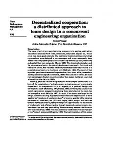
Fig. 1.
Stakeholder User
Constraints minimal cruising range
Vehicle Charging Station and Network Operator
mobility guarantee immediate consumption of available regenerative energy, feedback of regenerative energy during peak load
W2V2G System Architecture
Due to the logical distribution, our energy management system is designed as a decentralised multi-agent project which builds upon JIAC V [5], a multi-agent-framework developed at DAI-Labor. Specialised software-agents are designed for the management of different aspects, such as drivers, vehicles and its batteries, charging stations and the energy grid. They cooperate to optimise the overall benefit of the involved roles based on their aims (CO2 reduction, mobility guarantee, system load balancing). Their engagement is based on the planned usage
Responsibilities definition of the ecological attitude and risk attitude of the user energy management capacity management, support of load and wind forecasts, AAA
As shown in Figure 1 the different stakeholders are modelled as distributed software instances. Each software instance cooperates with the other instances to generate a shared and optimised solution, following their respective constraints.
292
The planning process is initiated by the user agent, since the user decides about the vehicle’s utilisation. The user agent accesses the user’s mobility pattern, which consists of two sources: Derived mobility patterns based on data about former journeys and upcoming appointments (time/place) in a calender. These informations are passed to the car agent who starts its consumption planning process, in order to develop the expected energy consumption of the vehicle. Thus the user’s mobility patterns are transformed into a expected journey schedule. For the computation of each journey the car agent accesses a route planner in the backend. The route planner was developed based on the freely accessible OpenStreetMap2 framework, providing different calculation modes, such as shortest and fastest path. In combination with a simplified consumption model provided by each vehicle type the car agent is now able to estimate the energy curve throughout for a given time frame, for instance for a day. The estimated energy curve is the basis for the W2V2G energy management, which is used to plan charging and discharging events. The algorithms to calculate the charging and discharging events are discussed in the following. The W2V (charging of electric vehicle’s battery) algorithm defines its trigger to (re-)schedule a charging event whenever the computed, prospective energy progression curve falls below the user-defined minimal cruising range. In this case all time intervals (more precisely the holding times of the vehicle) until the estimated undercut are verfified regarding its suitability for charging. Relevant attributes are the effect of the charging time interval to the vehicle’s energy progression curve as well as the prospective state of the grid. After filtering all time intervals that are not able to increase the curve above the minimal range, the remaining options are solely regarded under the aspect of expected regenerative energy and the system load. Therefore a charging interval should feature a high regenerative fraction and a low system load. More formally a charging interval is preferred to another if the quotient of regenerative energy to system load is higher. Doing so, the vehicle is mainly charging regenerative energy which leads to an ecological benefit. Further the consumption of the energy serves for the load peak grading, especially when embedding the V2G functionality. The Vehicle-to-Grid (V2G) planning is triggered by the car agent whenever the mobility pattern of the user has been changed. In that case all possible feeding intervals are being recalculated. Since, in contrast to the W2V algorithm, the initial trigger for feeding energy is not a constraint violation by the user. Possible feeding intervals are primarily filtered regarding the grid’s prospectives. Doing so, a possible feeding interval is superior to another if the grid load is higher and the fraction of regenerative energy lower. The grid load of an interval is set into relation to the daily maximum prospective load. If it undercuts the fraction of 0.9 (which has been deduced by simulated experiments on system load curves) 2 http://www.openstreetmap.org/
the interval is discarded immediately. Otherwise the fraction between grid load and regenerative energy defines the quality, whereby a higher value is preferable. Having evaluated the best interval the car agent checks whether the feeding event violates the user’s constraints. If so, the algorithm goes back to the second best interval and evaluates its validity to constraints. If none of the feeding intervals is valid to the user’s constraints the car agent tries to neutralise the violation by searching for another charging event. If this option does not lead to a result as well, the V2G algorithm aborts. In order to realise the scheduled charging and feeding events the vehicle has to park and be connected at a (V2G-capable3 ) charging station. If the vehicle is located at a predefined home or working position the algorithm assumes that an accessible charging system is available. However, if the vehicle is driven to an external place the car agent accesses a charging station booking service which provides information about charging stations in the vicinity. The details of the charging stations (type, reservations) are determined via an interaction with the respective charging station agent. In our approach we assume that the car can book charging / discharging events in advance. This approach leads to a high degree of planning reliability for all entities. The above described planning process is based upon expected driving behaviour of the electric vehicle. In reality the course of events can deviate from the scheduling due to unpredictable occurrences. Therefore the planning system must also consider dynamic rescheduling at runtime. In our approach the car agent continuously interacts with the control system to recognise such violations. In a first instance the planning system can handle cases like unregarded charging events. In that case the energy management system reschedules the charging plan for the remaining day. Further violations, such as higher consumption and unexpected journeys are already recognised but the resolution to these cases are not implemented yet and are considered as future work. B. V2G control and monitoring system The V2G control system takes over the task of monitoring and managing the high-voltage components of the vehicle. By accessing the CAN-Bus of a MINI E vehicle the control system reads out its specific data, such as state, charging capacity, battery voltage, state-of-charge, energy consumption and the temperature of the battery. If the V2G Mode is being activated the control system sends the requested charging / feeding capacity. Further the control system monitors the authentication and authorisation of the user during the buildup of the Power Line Communication (PLC) after the charging cable has been connected. The possible outcoming events and its related actions are: • Started: Change to V2G mode without charging current, in order to avoid unplanned charging of the vehicle after a successful connection 3 A V2G-capable charging station should contain a bidirectional energy meter and must fullfil the requirements of the distribution system operator (e.g. in Germany the standard DIN V VDE V 0126-1-1)
293
•
•
•
Connected: Connected to the electricity network and voltage is applied. The vehicle is trying to charge / feed with the designated amperage Error: V2G mode is being stopped, since the connection to the elctricity network was not possible due to a failed authentication or authorisation Interrupted: V2G is being stopped due to a log off or interruption from/to the electricity network
The V2G control system is being used by the planning system to activate the V2G Mode and to request the actual vehicle’s state in order to recognise rescheduling necessities. Since the evaluation of the energy management system should also be possible within a simulated approach, a car emulator component has been developed that is responsible for the emulation of the vehicle-sided state parameters. It can be configured regarding the maximal amperage for charging and feeding as well as the nominal capacity and voltage of the battery. It provides access via the CAN-Bus interface and is used by the V2G control system. When receiving a message by the control system the V2G mode is being (de-)activated. If the activation message contains a time interval for the V2G mode the emulator is able to emulate to adapt the state-of-charge of the battery. So, in our simulation approach, the adpation of battery states during charging and feeding is processed by the car emulator while the decrease of the battery state-of-charge during journeys is computed by a simulation environment and finally sent to the car eumlator. C. Authentication, Authorisation and Accounting The infrastructure for location-independent nondiscriminatory access to the charging infrastructure with multiple energy providers, network operators and customers is realized based on established standards and components from the ISP (Internet Service Provider) and mobile telecommunication domain. EAPoL/IEEE 802.1X [6] is used as authentication method between vehicle and charging station, whereas RADIUS [7][8] is used as the core AAA protocol between charging station and operator, assuming the operator implements remote and near real-time metering. Similar solutions are used in the telecommunications sector, where they form the technical basis for unbundling of networks and services. In the area of e-mobility, the protocols and software components used are adapted to the processes and regulations specific for this domain (e.g. cryptographically signed meter data and online/offline operation modes). EAPoL, as authentication method between vehicle and charging station, allows the utilisation of multiple technologies for authentication, for instance with a username/password, SIM card, or cryptographic certificates. Two of these methods were implemented, the password based EAP-MD5 [9] and the certificate based EAP-TLS [10]. To separate the user identity from the vehicle, a USB token was used. With this approach, many scenarios are possible, e.g. 1-vehicle-n-driver (families, car sharing), n-vehicles-1-user (rentals), or 1-user-n-contracts (private or business usage).
RADIUS is a standardised and well established protocol for user authentication and accounting and serves together with a AAA backend server for this purpose. The standard explicitly allows to incorporate Vendor Specific Attributes (VSA) to extend the basic functionality of the protocol, the VSA’s are used to represent the consumed and the supplied energy meter data. At the charging station data about the access (timestamps, user information) are associated with the metered data about the consumed or supplied energy and transmitted to the server at the backend. These access records are the basis for a downstream billing process. With RADIUS, or a comparable standardised protocol, an operator and manufacturer independent charging infrastructure is possible. IV. E VALUATION For the evaluation, we decided to use a simulation based approach. However, since we were dealing with electric vehicles, we had to consider the particular restrictions and characteristics which are associated with an electric powertrain. Compared to conventional, fuel driven vehicles we had to account for several aspects, such as range limitations or extended idle times while recharging the simulated vehicles. We performed a comprehensive analysis on the requirements of simulating electric vehicles and tried to identify an existing traffic simulation platform which is able to meet the demands of e-mobility [11]. We were not able to find an appropriate framework and as a consequence, we custom developed an event driven, microscopic traffic simulation platform [11]. Foundation of our simulation framework is a generic vehicle model, which allows for an easy replacement of the applied consumption characteristics of the simulated vehicles. Exploiting this feature, we were able to compare entirely different types of vehicles, namely electrically- and fuel driven ones. Instead of focusing the simulated vehicle for itself, we consider the driver and his “events” as central instance. This allows us to easily switch between different driver profiles, such as commuter- or weekend scenarios. To measure the efficiency of the introduced planning system, we had to consider one further aspect. In this paper we describe an assistance system, which is able to increase the efficiency in using electric vehicles. Yet, in order to determine in how far efficiency is increased, one has to compare the effects of applying the assistance system to “regular behaviour” without any assistance. For this purpose, we formulated a cognitive actuation model [12] with the objective to mimic the daily driving- and charging profile of human beings in a lifelike fashion. We extended our so far simulation framework with the actuation model [13] and most recently refined our implementation for the second time [14]. For our evaluation, we used the above mentioned actuation model to generate the behaviour of drivers which do not apply any assistance system. We compared the simulation outcome of these “unplanned” drivers to those whose behaviour is generated by the presented planning system. After this short introduction into the applied simulation techniques, we proceed by describing our simulation scenario in more detail.
294
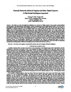
A. Scenario Setup Our planning system is highly depending on plausible wind as well as grid-load profiles. In order to emphasise the practicability of our approach, we had to use as realistic data as possible. For this reason, we made use of historic data sets for both, wind occurrences4 and the overall grid load5 , which we had to scale in a linear fashion, in order to obtain suitable input parameters for our simulation. Figure 2 shows the two curves for our scenario. These are the fundament for the charging priority, which is represented by the different types of shade in the background. Darker intervals indicate slots with priority for charging while bright ones are slots with priority for feeding energy.
simulation in which the behaviour was generated from the actuation model [14] we have outlined above. For the fuel driven vehicle, we used original consumption data7 of a Mini Cooper S and performed one simulation in which the behaviour was generated by our actuation model only. To compare the results of three simulations, we had to find a key performance indicator for the efficiency of our planning system. We decided to attend our focus on the CO2 efficiency. We present the results of the three performed simulations in the following. B. Results For the fuel driven vehicle, we calculated an overall CO2 emission of 18.126 gram. Basically, the data is independent from any grid load or wind availability prediction but expressively emphasises the difference between both applied powertrains. For the unplanned electric vehicle, we calculated an overall CO2 emission8 of 4.283,53 gram, while for the planned vehicles, the planning system was able to reduce the emission value to 2.364,57 gram – almost half the emission of the unplanned vehicle. The results are illustrated in Figure 3.
Fig. 2. Absolute amount of regenerative energy (line with dots; in MW) within the grid and its load. The background colors indicate the deduced charge priority signal (Bright intervals represent priority for charging, dark intervals priority for feeding)
For the mobility pattern of the simulated vehicles we exploited the user-centric principle of our simulation framework and configured a common commuter scenario. In order to ensure reliability, we made use of a common mobility study [15] to define the particular characteristics of the commuter profile. Our commuter profile is based on a regular working day, which we extended by further appointments before and after the user’s labour time. In total, the entire required route for the set of appointments is 133,28 kilometers, or 82,82 miles. Although the first use of the vehicle is scheduled not before 7 a.m., the simulation starts at 10 p.m. of the previous day, when the user connects his electric vehicle to his home charging station. We made this design decision in order to account for the major time of residence: The night time. Throughout the day, the user accomplishes his daily appointments, while he is able to make use of public charging infrastructure. We made use of the OpenStreet Map (OSM) framework [16] and applied an OSM map from the capital region of Berlin, from which we derived original positions of charging stations and which we also applied as simulation topology. h For the electric vehicle, we applied 0,2083 kW km , the average 6 consumption of a MiniE, and respectively ran one simulation in which we made use of the planning system and one 4 http://www.enbw-transportnetze.de/kennzahlen/erneuerbare-energien/
windeinspeisung 5 http://www.enbw-transportnetze.de/kennzahlen/vertikale-netzlast 6 http://www.mini.de/minimalism/product/mini e/index.html
Fig. 3. CO2 Emissions in gram of the simulated Mini E (planned, unplanned) and Minicooper S vehicles.
The large difference can be explained by the different selection of charging intervals. While unplanned vehicles selfishly decide on performing a charging process, the planning system preserves a bigger picture and takes additional criteria into account. For our example, the planning system performed an optimisation with respect to grid stability and CO2 efficiency. The outcome of this optimisation is impressively, since we have been able to significantly reduce CO2 emissions for the same mobility pattern by almost 50 percent. 7 http://www.mini.de/mini/cooper
s/information/index.html determine the emissions of vehicles with an electric powertrain, we had to assume an energy mix for the initial battery level of our vehicle. We assumed an energy mix which features a 20 percent share of nuclear and g fossil energy with an emission fingerprint of 683,80 kW and an 80 percent h g share of wind energy with an emission fingerprint of 24,00 kW . h 8 To
295
V. C ONCLUSION
VII. ACKNOWLEDGMENTS
In this paper we described a management system, which considers electric vehicles as distributed, temporary energy buffer. The benefits of our approach are twofold. In the first place the system facilitates an increased utilisation of alternative energy sources. Further, a certain amount of electric vehicles can be considered as distributed auxiliary batteries and support energy grids either on household- or on local network dimension. We started our work with a short description of the main showstoppers of electric mobility and emphasised our objective to consider those for our work. We performed a comprehensive survey on smart charging infrastructures and came to the conclusion, that the subject is currently an active topic of research. While many approaches have been described, results of fieldtest are rather short. The reason for that is the required hardware, which only just became available. As a result, many approaches have been evaluated on a simulative level. For this paper we introduced the most similar related work and proceeded with our approach. We emphasised the distributed nature of the system at hand and thus motivated an application of the agent oriented programming paradigm. We further introduced the main system roles and described their purposes and their implementation in detail. For the evaluation, we configured a typical commuter scenario and performed three simulations in which we respectively exchanged the consumption characteristics of the applied vehicle. We presented the CO2 emissions of each simulation run and came to the conclusion, that the introduced management system is able to reduce emissions by almost 50 percent. Based on these convincing results, we feel confident to continue our efforts in the domain of management systems for electric mobility. VI. F UTURE W ORK Within the running project “Gesteuertes Laden V2.0” we are actually working on the enhancement of the effectiveness and efficiency of the W2V2G system. This will be realized by better planning algorithms that take into account elements like user profiles, charging curves, dynamic wind and load prediction, but also topology and properties of the local grid. Even reservations of charging stations are taking into account in order to maximize the usability of electric vehicles. A developed smartphone application will also increase the acceptance by the drivers. The system will be tested in an outdoor laboratory with a number of vehicles. Last but not least, simulations examine the functionality of the system and the impact on the environment in the event of many vehicles and charging stations under certain conditions. For future projects the provisioning of ancilliary services and the development of business models (e.g. dynamic tariffs) are planned to make this approach more attractive for all actors especially for the vehicle owner.
This work is partially funded by the Federal Ministry for the Environment, Nature Conservation and Nuclear Safety under the funding reference number 16EM0004. R EFERENCES [1] Nationaler Allokationsplan 2008-2012 fuer die Bundesrepublik Deutschland. Bundesministerium fuer Umwelt, Naturschutz und Reaktorsicherheit, June 2006. [2] J. A. Peas Lopes, F. J. Soares, and P. M. Rocha Almeida, “Identifying management procedures to deal with connection of electric vehicles in the grid,” in Proceedings of the 2009 IEEE Bucharest Power Tech Conference, 2009. [3] A. Schuller, “Marktintegration der Elektromobilit¨at: Ein agentenbasierter Ansatz f¨ur das Smart Grid,” in Energieinformatik 2010, vol. 1, no. 1. Offis - Institut f¨ur Informatik, 2010, ISBN:978-3-00-032747-6. [4] M. D. Galus and G. Andersson, “Demand management of grid connected plug-in hybrid electric vehicles (phev),” 2008 IEEE Energy 2030 Conference, pp. 1–8, 2008. [Online]. Available: http: //ieeexplore.ieee.org/lpdocs/epic03/wrapper.htm?arnumber=4781014 [5] B. Hirsch, T. Konnerth, and A. Heßler, “Merging Agents and Services — the JIAC Agent Platform,” in Multi-Agent Programming: Languages, Tools and Applications, R. H. Bordini, M. Dastani, J. Dix, and A. El Fallah Seghrouchni, Eds. Springer, 2009, pp. 159–185. [6] T. Jeffree, Port-Based Network Access Control. IEEE Standard for Local and metropolitan area networks, IEEE 802.1X, 2004. [7] C. Rigney, S. Willens, A. Rubens, and W. Simpson, RFC 2865: Remote Authentication Dial In User Service (RADIUS), 2000. [8] C. Rigney, RFC 2866: RADIUS Accounting, 2000. [9] B. Aboba, L. Blunk, J. Vollbrecht, J. Carlson, and H. Levkowetz, RFC 3748: Extensible Authentication Protocol (EAP), 2004. [10] D. Simon, B. Aboba, and R. Hurst, RFC 5216: The EAP-TLS Authentication Protocol, 2008. [11] M. L¨utzenberger, N. Masuch, B. Hirsch, A. Heßler, and S. Albayrak, “Predicting future(e-)traffic,” in Proceedings of the 9th Industrial Simulation Conference, Venice, Italy, S. Balsamo and A. Marin, Eds., Eurosis. EUROSIS-ITI, June 2011, pp. 169–176. [12] M. L¨utzenberger, N. Masuch, B. Hirsch, S. Ahrndt, A. Heßler, and S. Albayrak, “The BDI driver in a service city (extended abstract),” in Proceedings of the 10th International Joint Conference on Autonomous Agents and Multiagent Systems, Taipei, Taiwan, K. Tumer, P. Yolum, L. Sonenberg, and P. Stone, Eds., Mai 2011, pp. 1257–1258. [13] M. L¨utzenberger, N. Masuch, B. Hirsch, S. Ahrndt, and S. Albayrak, “Strategic behaviour in dynamic cities,” in Proceedings of the 43rd Summer Computer Simulation Conference, The Hague, The Netherlands, June 2011, pp. 148–155. [14] M. L¨utzenberger, S. Ahrndt, B. Hirsch, N. Masuch, A. Heßler, and S. Albayrak, “Strategic behaviour in a living environment,” in Proceedings of the Winter Simulation Conference, Phoenix, AZ, USA, December 2011, to appear. [15] Mobilit¨at in Deutschland 2008. Bonn and Berlin, Germany: Federal Ministry of Transport, Building and Urban Development, 2010. [Online]. Available: http://www.mobilitaet-in-deutschland.de/pdf/ MiD2008 Abschlussbericht I.pdf [16] F. Ramm and J. Topf, OpenStreetMap: Using and Enhancing the Free Map of the World, 1st ed. UIT Cambridge Ltd., September 2010.
296