u.wr~riq. II' this nc\r vccior spiicc rcprcscntcd by a unit coiisisrs 01' aril), ;I single signature, thcn thc fault case associarcd wirli hiit signature can hc isolated.
Analog Fault Diagnosis: A Fault Clustering Approach Shyam S. Somayajula, Edgar Srinchez-Sinencio & JosC Pineda de Gyvez Electrical Engineering Department Texas A&M University College Station. TX 77833-3 128, USA npproacli capahlc to ovcrcomc thc abovc limitations. Thc basic idea of this incthodology consisLs of training a ncural nctwork paradigm. Thc training input vcclor has a set of A novel analog circuii firult dicignosis ineihod is data points consisting of familics of simulatcd faulty as proposed. This method uses a neural network paradigm to well a s friult frcc bchaviors of thc circuit. Thcse inpct cluster different faulis. It is capable of dealing with ihe vcctors arc callcd signuiures. Thc neural nctwork common fault models in ~ n a l o g circuiis, nomely ihe palati igm cl assi fics these signaturcs into differcnt clusters. catastrophic and paranieiric fauiis. The proposed The actual expcrimcntlil vector callcd the lest vector, technique is independent of ihe lineariiy or nonlineariiy of oblaincd from thc circuit undcr tcst, is thcn prescnted to the the circuii. The process pciramcier drip fis rind coinponeni ncural network. The network outputs thc clustcr of known iolerance effects of ihe circuii ore well iciken carc of: signaturc(s) that bcst matchcs this tcst vector. This Several fault diagnosis siraicgies for differeni problem approach allows thc tcsting as wcll as thc diagnosis of the circuit. Scvcral dcgrccs of complcxity of the proposed complexities are described. The proposed meihodology is illustrated by mean.7 of (in Opcruiinnnl 7r~tiscondrtci~t~1:c technique arc introduccd in this papcr. The practical and thcorctical aspccts of this techniquc arc verified and Amplifier ( O l A ) example. illustrated by inciins ol'an IC cxample. Alxtruct
1: Introduction Analog circuits haw rcachcd ccrtiiiri inaturity i n [tic past few dccadcs. Howcvcr, tlic analog fault diagnostic techniqucs arc still very inodcst. For analog circuits, I'iitrlt diagnostic tcchniqucs arc more complcx when comparcd to their counter parts in digital circuits lor various rcasons. The circuit componcnt tolcrancc in fault frcc and faulty circuits, the nonlincarity propcriics ol' analog circuits and the limited access to the intcmal nodcs o f thc circuit bcing the the major factors that contribuic to its complcxity. Many diffcrent analog fault diagnosis inclhotis havc bccn proposed [ 11-[31, PI-[ 131. Current analog Tault diagnostic techniques oftcn sulfcr the additional problcms of i) Incrcascd silicon arcii and power consumption with built-in sclf tcst circuits [4], ii) The requirement of mcasurcmcnts of current and voltagc signals at intcmal nodes and iii) Thc lack of good niodcls to simulate thc circuit undcr tcst. Wc propose a nonconvcntional and morc gcncral
A
nctwork
is
a
fcaturc
mapping
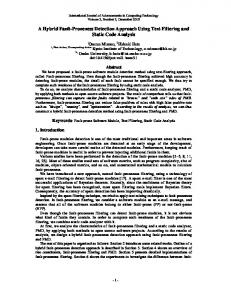
nctwork. Fig. 1 shows its basic structure. The layer consists ol'N ordcrcd proccssing clcmcnts cach receiving n inpill signals X I , s:, x? ... x,, coming from an +dimensional Eucliticnn spacc. A weight wy is
108
0-8186-3360-3/93 $03.00 0 1993 IEEE
Kohoncii
scll-orgurii / i iig ne ural nctwork with unsupcrviscd compc[i[ivc Icnrning [ 51. The charactcristics of this nctwork is t h a l it maps a givcn random input stimuli space to a cliisior spacc composctl of' distinct clustcr elemcnts. For csamplc, a Kohoncn nctwork can bc used to highlight a Icttc,r, say, "A", from a given sct ofcharactcrs consisting of lcttcrs and numbcrs and wriitc.cn in any calligraphic stylc. AI'tcr training, tlic network should bc ablc to group all "A's" of various calligraphic stylcs in one single cl ustcr. Let us bricl'ly describe the behavior of a Kohonen
I
a lrcquc.ncy domain, time domain or a dc analysis using a circuit simulator such as HSPICE. Data is oblaincd by simulating rhc circuit wilt1 the Inult induced and thcn by sampling ilic rcsponsc a t n dillcrcnt points. This proccdurc is rcpcaicd for each I i u l t case a nd for thc kiult Trcc circuit. We dcnoic thc set of data points as an n-dimensional .signcirurc. Next, ;1 Kohoncn nctwork with n inpuls and N proccssing clcrncnts, where N is thc numbcr of BCs and n is the diinc-nsioniilityof thc signnturc, is traincd according to thc algorithm described in Appcndix. Thc Kohoncn nctwork maps tlic signatures from thc initial random vector sI>iicc o n t o thc proccssing clcmcnls. This vcctor mapping propcrty of the Kohoncn nctwork is uscd to clnssily the signatures, and thus, to idcntify the faults. Fig 2. shows our I'iiiilt--diagi1osis procedure. A clustcr tahlc is gcncr:itcd by recording the winner proccssing unit l o r cach input signature. If ;I unit wins for more than onc signature, thcn the fault casts associatcd with those signatures arc said to hc collnpsing ,fnidls. Thcse faults c;innot be isolated I'rom each othcr using only thcse signatures. We dcnorc the phcnomcnon of rcducing thc initial vcctor space, that includes all thc signaturcs, to a v L x t o r pic cc consisting of h e r signaturcs its ,fiudf ~ . / u . w r ~ r iII'q .this nc\r vccior spiicc rcprcscntcd by a unit coiisisrs 01' aril), ;I single signature, thcn thc fault case associarcd w i r l i h i i t signature can hc isolated. This is rc I'c rrcd to iis f;iI L / I isdui io/, .
2
Fig. 1. Khonen Network Archit&ture associatcd with thc jth Kohoncn prcxcssing clcmcnt anti the ilh input signal. Each Kohoncn proccssing clcmcnt calculates a matching scorc M; according to the formula : Mj= D(I%, X). WhCrCr\/j= ( w/,;, y;, i~?; ... wC;j'' , X = ( X I , x2, x3 ... &)l' and thc function D((1,h) is a distance mcasurcmcnt function. Thc Euclidean tliskincc, D(a,b) = la - bl, is a common mcasiirc uscd in many applications. Input signal vcctors X, randomly taken from the input spacc, are prcscntcd to the nctwork one at ii time. The numbcr of input vcctors can hc Q , Q S N . Once cnch Kohoncn proccssing unit has calculatcd its matching scorc M;, a compctilion takes place in the Winner Tikc All loycr (WTA) to dctcrminc which ol' the uniis has h e sniallcsl matching scorc, i.c to I'ind our rlic wcigtir vector 14; that most closcly rcscmhlcs the input vcctor X. Matching score ( M, tics arc brokcn bnscd on tlic proccssing u n i t indcx numbcr. Thc unit with thc smallcst matching Iictor is callcd thc winner.A unit can win lor inorc than onc input vector X or may not win at all. The winner lor a particular vcctor(s) is said to rcprcscnt that vcctor(s). Thc learning is implcmcntcd by updating thc wcights by ;I fraction q such that M, is minimized. SCCAppcndix for thc algorithm.
3.2: Opt inia I Saiiipl iiig Points A good critcria was proposed in onc of thc earlicst tcchniqucs for conslructing Paul t dictionarics for lincar I'rcqucncy dcpcndcnt circuits 161. This critcria has been uscd ever sincc [ 7-81. As o u r tcchniquc involves ac, dc and triinsicnl nnulyscs, an altcrnatc mcthod was devclopcd. This tcchniquc is ii compromisc betwccn a good rcprcsc.ntaiion or all tlic rcsponscs and thc numbcr of sampling points. Lcsscr sampling points implics smallcr Kohoncn networks and hcncc shorter training pcriods. The hasic idea is to obrain the responses w i t h a good numbcr of sninplin? points and compurc independent-scts of s:iniplinp poinrs l'or cach sipn:iturc b y Liking the dcrivative 01' i l i c curve ontl including the points iit
3: Fault Diagnosis Methodology 3.1: Procedure A set of signaturcs is obiained from sampling the response of thc circuit for various behavioral conditions (BC). Thcsc BC's include ihc liiult I'rcc ciisc and ii predcfincd sct of faulty CN-S such ;is shoris a n d hrc.:tks. Thc responses (signaturcs) c m bc oblaincd b y pcrl'orniing
109
T*Lc
Stcp 1 : For cach signaturc i do Compute clc\~iaiionl= (Mi(t) - Mi(t-1)1/Mi(t-I))*loo Compute dcviation2 = 1 Mi(() - M,(t-2)I/Mi(t-2))*100 il'dcvin~ionI > dcvirrlioti Iricludc t in thc indcpcndcnt-sct IS(i) clscil' dcviation2 > deviulion inclutlc t in indcpcndcnt-sct IS(i) G o IO Stcp I
I
I
I I
k z l I
& I
I+Gct diagnosis results
Stcp 2: For cnch point pES(i) it'( p E IS(i) ) includc p in y. Go to step 3
I
Sim ul at c
+ Iw
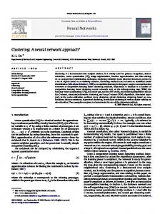
Fig. 3 s h o w s thrcc curvcs which arc gcncrated with a sct of
Get si naturcs
I
Curve. Curve.
40 ), f
/ '\ \
' -0
0
2
3
6
8
10
Fig 3: Optimal Sampling Points Fig. 2. Fault diagnosis procedure
tcn point\ cach. Applying thc algorithm to thcse signatures yields the markcd points for cach signaturc. The y sct includci; points 0, 2, 5 , 7, 8, 9.
4: Practical Results
which the absolute valuc of thc dcrivativc is grcatcr than ii rcfcrencc paramctcr cfcvintion. Thc sct o f optimal sampling points, consisting of all Ihc points in the above indcpcndcnt-sc.ts, is thcn oblii incd. Thc 01 gori thin bclow implcmcnts thc proposed mcihod. Obscrvc that the parameter deviafion is ad.iuskiblc and offcrs a dcgrcc of freedom to control thc sct of sampling points. A dcviation of 5% is used in ourcxpcrimcnt. Lci Mi([) is thc mngnitudc of thc signaturc at poini I, S(i) is the initial sct ol' poinls uscd to gcncrntc the curves and y is ihc opiimal sampling point set.
The tcchniqucs prcscnicd prcscntcd arc icsted on the OTA circuit shown in Fig 3a. A set of 11 BCs, listed in Table 1, is considered and thc circuit is simulatcd using HSPICE. For illustration purposcs, only singlc bridging faults are consitfcrcd lor verification of thcsc tcchniqucs. Thc bridging faults iirc niodclctl by a SS2 rcsistor. For the casc 01. nicasurcni~~n~, rhc OTA is conl'igurcd ;is shown in Fig. -It). Tlic o i i i p u ~currciii is otmincxl I'rom the ac analysis and I t i c in:iy~ilridc 1 5 ploiictf I'or cacti BC ovcr a frcqucncy
110
I
2 01
I O
*w 0i s1 i z
6 01
I 01
(LIIII
Plot. 1. Signatures of the OTA.
-
A broader classification of fault clustcrs is accomplished using thc basic technique described abovc. However, a finer isolation of lhcse clusters can bc obmincd by using a combination of Kohonen nctworks and/or mu1tiple analyses. This strategy yields four categories: 1) Single Kohonen Single Analysis (SKSA) 2) Multiple Kohonen Single Analysis (MKSA) 3) Single Kohonen Multiple Analysis (SKMA) 4) Multiple Kohonen Multiple Analysis (MKMA)
(b) Fig. 4. OTA
(a) Circuit (b)Configuration
Table 1. Behavioral Conditions
4.1: SKSA Approach: This is the simplcst of all thc approachcs. A possible fault classification is shown in Fig. 5. Thc cllipscs represent a clustering of BCs. Hcrc. thc signaturcs are generated by simulating thc circuit with cach induccd fault and by performing a dc, ac. or transicnt analysis sampling the response at thc output nodc. Thc rcsulic; obtaincd for the magnitude of the frcqucncy rcsponsc arc shown in ihc second column of Tablc 2. M'c scc thilI thcrc arc X clustcrs two of which indicatc collapsing l i ~ ~ l naincl! t ~ , BCs 0.9 and BCs 6,7,8.Similar rcsults wcrc obtaincd lrorn a dc analysis. a phase analysis, and a transicnt analysis. though the contents of the clusters diffc.red in cach case.
1-1 111
BC
Short Bctwecn Nodcs
0
f ; ~ ~ Cree lt
1
14
2
4-5
3
1-3
3
6-8
5
2 -9
6
1-7
7
9- I O
IO
3-5
4.2: MKSA Approach :
obuiincd hy i) pcrforining ;I diffcrcnt analysis ii) laking thc rcsponsc ai difrcrcnt access poinb in the circuit. The laticr option is oftcn inorc cxpcnsivc than the first one as it has an ovcrhcad of a fcw morc pads in thc chip. For our cxpcrimcnts, thc phasc rcsponsc of the circuit is uscd to obtain ncw signaturcs. Thc clustcring done by this approach is shown in thc 3rd column of Table 2. By inspccting ihc rcsults of boih analyscs wc can sec that BCs 5 and 6 arc now isolatcd. This docs a bcttcr fault collapsing than the SKSA at thc possihlc cost of additional analyses.
In this approach morc than one Kohoncn nciwork is used. The generic architccturc is shown in Fig. 6 . Thc boxes rcprescnt new Kohoncn nctworks trained on the signatures corresponding to the magnitude of a frequcncy analysis. In this structurc, thc BCs yiclding fault collapsing in thc SKSA arc uscd to train anothcr Kohoncn network to obtain further classification. As thc vcctor spaceis now rcduccd lo includc only thc signaturcs that arc clustered together, Lhc nciwork now has io w i n on a niorc uniform distribution of signaturcs. Thc information from the signatures is utilized to the maximum possihlc extcnt in this approach.
Table 2. SKSA and SKMA results
n I '3' Bchavioral Condilions
KOHONEN NET
I
Clusters
Fig. 5. SKSA Architecture Considcring Lhc output of thc two rcctangular boxcs markcd Mugniiurlc in Fig.7 thc BCs 7 and 8, ihai arc clustered togcthcr in Lhc SKSA approach, arc isolated from each othcr in this approach. Wc scc that ii classification bcitcr than thc onc ohtainctl Iron1 thc SKSA is achicvcd. This technique is quite inexpensive and can he used its ;t prcprocessor to reduce the scarch spacc. This idcu is analogous to thc Ihult collapsing tccliniquc donc in digital testing.
4.4: R4KiR4A Appro:ich A ncw' set ol' signuturcs iirc gcncraicd only for those l l u l i casts chat arc clusicrcd togcihcr in thc MKSA approach. Thc MKRIA archiicciurc rcprcsencs a trcc in which cacti Kohoncn nciwork can bc traincd on diffcrcnt
analyses. I n our cxpcriincnts ncw scts of signaturcs arc ohiainctl I'roin ilic phasc rcsponsc. Thcsc signatures arc gcncraicd only for faulis that arc collapsing. In our casc, tor BCs 0, 8,s and 7. Thc dcpth of thc trcc, the numhcr of Kohoncn nctworks and thc nuinbcr of diffcrent analyscs arc thc important Iiictors in this mcthod. Thcsc are thc mctrics uscd for comparison of thc dcgrcc of classification obtiiincd l'rom ihc wholc proccss. Fig. 7 shows that all the
4.3: SKMA Approach: This Single Kohoncn Muliiplc Analysis tcchniquc yiclds a bcttcr classification of BCs. Undcr this approach, the same Kohoncn nciwork can bc uscd (as thc architcciurc is thc same) for signaturcs of diffcrcni analyscs by rc-initializing thc wcights. Difrcrcnt signnturcs can hc
112
Behavioral Conditions
Bchavioral Conditions 0 1 2 3 4 5 6 7 8 9
....
Magnitude (Frequency)
10
Magni tudc
-
4
, .....>r.............. ...n::::i:i:iiiii(ii~~:~:~::: .... .i.
Magnitude
Phasc
...
t
........,...... ..... ....\\.. ... .., :.
Phasc
0 x I 2 3 4 9 105 7 6 Fig. 7. MKMA Kohonen architecture for the OTA lo I I o w i np IC' ICT ii II I 1 c ;I t ti rc s:
Fig. 6. MKSA Architecture BCs arc in fact isolatcd. The dcpth 01' thc tree depends on the rcsponse of the sysicm, i.c ihc distrihution of' thc signaturcs in thc vcctor spacc, and nccd not necessarily depend on the nurnbcr of fault casts considcrcd. Thc laticr observation is invcstigatcd with similar cxpcrimcnts using 18 BCs. We could scc that all thc faults wcrc isolatcd and that the dcpth of the trcc, thc numbcr of Kohoncns and thc numbcr of analyscs wcrc the same li)r both cxpcrimcnls. This mcthod is sclf-sufficicnt as it can bc rcpenicd for a complcte isolation of f:tults. Many tcchniqucs havc bccn proposed that rcquirc nodc voltagc and current This tcchniquc measurcments mcasurcmcnts I?\-[9]. guarantecs the minimum usc of additional acccss points hcncc rcducing compuIiItional complexity and silicon overhead. If the signatures ohtaincd I'rom the rcsponsc o f the circuit at its output nodc for diffcrcnt analyses do not provide the desired classification, the signaturcs can thcri bc takcn from the rcsponsc at a tlil'fcrcnt notic \vhich provides thc dcsircd clussil'ication. Then, this notlc can he uscd as an observation point. Thus, any ;icccss poinls lor circuit observability, in addiiion to the ou~piitpad, can he determined by this approach.
1.5.1: Process \':ir.i;ition Independency
Current Simulation Bcforc Tcsi (SBT) techniqucs are liinitcd due to parainctcr drift and noisc. Using these icchniqucs, thcrc is a chance that a givcn signature is not among the storcd faulis in ihc dictionary, in which case litiilt diagnosis is not possiblc. In our approach, as the mapping is from thc signaturc vcccor space and not from ihc s i p i l tire itsclf, cl'fcctivc diagnostic results are obtaincd il' thc parainclcr drifi duc to proccss variation and noisc arc approsiinatcly 7-10% of thcir nominal valucs. This fc%urc was verified through the MKMA approach ovcr a sct ol' process parainctcrs for the MOS transistors uscd in ihc OTA. Test signatures wcrc obtaincd from thc circuit with Ihc proccss parameters changcd to within 10% of thcir iioniinal valuc. The rcsults obtaincd wcrc thc Sainc ;IS Ihosc ohtnincti \vith tcst signaturcs ohtaincd with thc noiniriiil process I)a"anietcrs.
1.5.2: Reduced Number of Access Points In all thc cxpcriincnlill rcsults prcscntcd in this paper, only thc circuit output is uscd to mcasure the response. The simulations with thc OTA show that a complete fault diagnosis is possiblc without additional access points.
4.5: Remarks And Observations Thc fault diagnosis mcthtxi prcscntcd in this papcr has thc
113
This is an important factor to consider whcn testing realistic systems.
1)Select the output node with minimum distance. Sclcct j* ;ISthe nodc wiili minimum disuncc.
4.5.3: Fault Model Independent
5 ) Update weights to node j* and its neighbors. Thc ncighborhood is ctcfincd by NE(j). This has a
This technique can be uscd to diagnose any kind of faults: i) bridges ii) opcns iii) soft faults iv) multiplc faults v) faulty operating conditions.
radius of thc cntirc proccssing units initially, and dccrcescs monotonically with thc itcrations(t). As the processing units arc uni-dimensional, the radius can be dccrcascd in stcps after ccrtain itcrations. Thc ncw wcighls lor thc winncr arc dcfincd by the lcarning rulc:
4.5.4: Extension to Digital And Mixed Mode Circuits The rcsponsc of thc circuit during the risc time and frill time can be used to gencrate nzixd-modo signatures. Cluster tables can bc gcncratcd using this tcchniquc for a digital and mixcd modc circuit in a similar fashion as indicated through out the papcr.
Wc use the cxprcssion ~ ( s )= 1/(400 + t) in our applicaiion. The lcarning rulc lor thc neurons in the neighborhood is ttic same LIS abovc cxcept that the Icarniny KIIC’ q ( ~will ) hc ;I dccrcasing function o f thc
5: Conclusions A powcrful non-convcniionnl unulog liiult diagnosis mcthodology has been proposcd. The approach bnscd on training a Kohoncu (neural) network has the potential to deal with hard and solt I‘aults, docs not rcquirc xiditional
is usctl lor tlic units that liill in thc neighborhood. 6) Repeat by going
ovcrhcad or additional silicon arca o f built-in scll lcst circuits or access to intcrnal nodcs o l thc circuit undcr tcst. It has thc potcntial to handlc mixcd modc circuits and multiplc faults. Prcliminary rcsults using practical integrated circuib arc vcry cncouraging
7: References [ I IR.-W. Liu, Ancilog Fciiclt Diczgnosis. IEEE Press, 1988.
[2]R.-W. Liu, 7iistinX cind Dicigrmis ofAnuloguc Circuits cind S y , w : t r i . s . Van Nostrand Rcinhold, 1991.
6: Appendix
13 IJ. M’. Bandlcr, anti A. E. Salama, “Fault diagnosis of
Kohonen Paradigm:
analog circuits.
”
Proc. IEEE, pp. 1279-1 325,
Aug.1985.
The algorithm uscd io implcmeni the sclf organizing fcaturc mapping Kohoncn nctwork lor our I i u l t diagnosis mcthod is as follows: 1)
to Step 2.
(412. F. Huang, C. -S. Lin, and R. -W. Liu, “Node-fault diagnosis a i i d ii tlcsign ol‘ tcstnbility” IEEE 7rnn.s.
Circ;/iii.\( / t i ( / S ~ . s i ~ ~Vol. t t ~ ,CAS-30, ~, pp. 257-265, May
Initialize weights randomly.
108.3.
2) Present new input pattern.
3) Compute matching factor Mi: compulc dislllnccs Dj bctwccn thc input and each
[(,I
N-1
output n d c j using
C(
~ , ( t >-
IV,,(~>1 2
i=n
114
S.Scshu and R.Waxman, “Fault isolation in convcntional lincar systcms - A feasibility study,” IEEE ’ l r 1 i n ~Rclicih.,vol.R-15, . pp. 11-16, 1966.
[7] R. E Garzia, “Fault isolation computcr mcthods,” NASA Contractor Rep. N A S A CR-17-55’, Mnrshall Space Flight Ccnicr, Huntsvillc, AL, 1971.
[ 1 1 IL.
Rupisarnda and R. DcCarlo, “Analog in U I1 i frcq ucnc y fa ti It diagnosis, IEEE Trans. Circuits cind S ~ . W ~ T I vol. . S , CAS-30, pp. 223-233, Apr. 1983. ”
[8lW. J. Stahl, J. H. Macnpaa, and C. J.Stchman, “Computer aidcd dcsign: Pari 13, dcfining f a u h with a dictionary,” Electronics, vol. 41,110.2, pp. 64-68, 1968.
Trick, W. Maycda, and A. A. Sakala, “Calculation of paramctcr valucs from node voltage mcasurcincnLs, IEEE Trans. Circuits and Systems, Vol. CAS-26, pp. 4M5374, July 1979.
[ 12lT. N.
”
[9]P. M. Lin, and Y. S . Elchcrif, ‘‘ Analoguc circuits fiiult dictionary- Ncw approachcs and implcmcntation, Int. J . Circuit Theory and Application, vol. 12, pp.149-172, 1985. ”
[ 13]C.-L. Wcy and S. Krishnan, “Built-in self tcst (BIST)
SLructures for analog diagnosis with current test data,”
[10]B. L. Jiang, and C. L. Wcy, “Fault prcdiction proccss for large analoguc circuit nctworks, Inil. J. Circuil TheoryandApplication, Vol. 17, pp. 141-149, 1989.
IEEE 7rcrti.s.Ins~ruin.Meos., vol 41, pp. 535-539, Aug. I992.
”
115
T