Abstract. This paper proposes a formal verification methodology which smoothly integrates with component-based system- level design, using a divide and ...
A Formal Verification Methodology for IP-based Designs Daniel Karlsson, Petru Eles, Zebo Peng IDA, Linköpings universitet {danka, petel, zebpe}@ida.liu.se Abstract This paper proposes a formal verification methodology which smoothly integrates with component-based systemlevel design, using a divide and conquer approach. The methodology assumes that the system consists of several reusable components, each of them already verified by their designers and which are considered correct under the assumption that the environment satisfies certain properties assumed by the component. What remains to be verified is the glue logic inserted between the components. Each such glue logic is verified one at a time using model checking techniques. Experiments, performed on a real-life example (mobile telephone), demonstrating the efficiency and intuitivity of the methodology, are moreover thoroughly presented. Three different properties have been verified on one part of the system.
1. Introduction It is a well-known fact that we increasingly often interact with electronic devices in our everyday lives. Such electronic devices are, for instance, cell phones, PDAs and portable music devices such as Mp3-players. Moreover, other, traditionally mechanical, devices are becoming more and more computerised. Examples of such devices are cars or washing machines. Several such devices are in addition highly safety critical, such as aeroplanes or medical equipment. In fact, in 1999, 99% of all microprocessors were used in the type of systems mentioned above (embedded systems). Only the remaining 1% was used in general purpose computers [1]. This situation indicates the big importance of embedded systems. Obviously, it is both very error-prone and time-consuming to design such complex systems. At the same time there is a strong economical incentive to decrease the time-to-market. In order to manage the design complexity and to decrease the development time, designers usually resort to reusing existing components (so called IP blocks) so that they do not have to develop certain functionality themselves from scratch. These components are either developed inhouse by the same company or acquired from specialised IP vendors [2, 3]. Formal verification tools analyse the system model, captured in a particular design representation, to find out whether it satisfies certain properties. In this way, the verification tool can trap many design mistakes at early stages in the design.
Since the trend is that systems are built more and more with reusable components, it becomes increasingly important to develop verification methodologies which can effectively cope with this situation and take advantage of it. There are several aspects which make this task difficult. One is the complexity of the systems, which makes simulation based techniques very time consuming. On the other hand, formal verification of such systems suffers from state explosion. However, it can often be assumed that the design of each individual component has been verified [4] and can be supposed to be correct. What remains to be verified is the interface logic and the interaction between components. Such an approach can handle both the complexity aspects (by a divide and conquer strategy) and the lack of information concerning the internals of predefined components. Assume-guarantee reasoning [5] is a method of combining the results from the verification of individual components to draw a conclusion about the whole system following certain rules. This has the advantage of avoiding the state explosion problem by not having to actually compose the components, but each component is verified separately. In this paper we propose a formal verification approach which smoothly integrates with a component based systemlevel design methodology for embedded systems. Once the model corresponding to the interface logic has been produced, the correctness of the system can be formally verified. The verification is based on the interface properties of the interconnected components and on abstract models of their functionality. Our approach represents a contribution towards increasing both design and verification efficiency in the context of a methodology based on component reuse. This paper mainly demonstrates this methodology on a reallife example (mobile telephone) by verifying three different properties. Each step of the methodology which has to be taken is carefully presented.
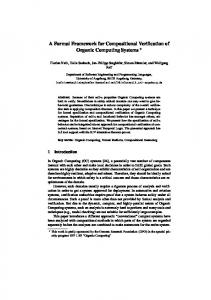
2. Methodology Overview In this paper, we consider systems which are built using predesigned components (IP blocks). Figure 1 illustrates such a system. Each component, in the figures throughout this paper, is depicted as a box with circles on its edge. The circles represent the ports of the component, which it uses for communication with other components. The glue logic inserted between communicating components is depicted in Figure 1 as clouds. For example, the interfaces of two or more components connecting to each
Ports
Component 1
Component 2
Component 3 Glue Logic
Component 4
Component 6
Component 5
Figure 1. Targeted system topology other may use different incompatible communication protocols. Thus, they cannot communicate directly with each other. For that reason, it is necessary to insert an adaptation mechanism between the components in order to bridge this gap. This adaptation mechanism would then be the glue logic.
2.1 Objective and Assumptions
Sender msgout
Glue Logic
AG ( ( status = disconnected ∨ init ) → A [ status = connected R ¬in = 〈 send, _ 〉 ] )
(eq. 1)
A set of such formulas is, as mentioned previously, associated to each interface of every component.
2.2 Performing the Verification The glue logic inserted between two components is to be verified so that it satisfies the requirements imposed by the connected components. Figure 3 illustrates the basic procedure. Model checking is used as the underlying verification technique. The model of the glue logic together with models corresponding to the interface behaviour of the interconnected components (called stubs) are given to the model checker together with the (T)CTL formulas describing the properties to be verified. A stub is a model which behaves exactly in the same way as the component with respect to the interface consisting of ports connected to the glue logic under verification. As a result of the verification, the model checker replies whether the properties are satisfied in the model or not. If they are not, the model checker provides a diagnostic trace in order to tell the designer what caused the properties to be unsatisfied. Surrounding
Stub Component 4
Glue Logic
Stub Component 5
Surrounding
The objective of the proposed methodology is to verify the glue logic so that it satisfies the requirements imposed by the connected components. The methodology is based on the following assumptions: • The components themselves are already verified. • The components have some requirements on their environment associated to them, expressed in a formal notation. The first assumption states that the components themselves are already verified by their providers, so they are considered to be correct. What remains to be verified is the glue logic and the interaction between the components through the glue logic. According to the second assumption, the components impose certain requirements on their environment. These requirements have to be satisfied in order for the component to function correctly. The requirements are expressed by formulas in a formal temporal logic, in terms of the ports in a specific interface. It is important to note that these formulas do not describe the behaviour of the component itself, but they describe how the component requires the rest of the system (its surrounding) to behave in order to work correctly. In this work, we use (timed) Computation Tree Logic, (T)CTL [5] for expressing these requirements. However, other similar logics may be used as well. (eq. 1) provides an example of a CTL formula being a constraint associated to a component. This example, also shown in Figure 2, is taken from a design using a connection-based protocol for communication. It consists of a component wanting to send a message to another compo-
nent at regular time intervals. The sending component is not aware of the connection-based protocol and consequently all its messages must pass through a third component called Protocol Adapter. The protocol adapter implements the chosen protocol and was supplied and verified by a provider. However, the protocol adapter needs an explicit command to connect to the receiving component, and messages to be sent must be preceded by a particular send command. Such commands are received through port in . The adapter moreover provides the glue logic with information about the connection status through port status . Receiving messages arrive through port out . It is the task of the glue logic to supply the adapter with the appropriate commands and to take care of the messages produced by it. (eq. 1) is associated to the protocol adapter stating that it is forbidden to send any message unless first connected.
in
send Protocol Adapter rec status out
TCTL formulas
TCTL formulas Model checker
Figure 2. A concrete example of a situation where the methodology can be applied
Satisfied Unsatisfied Diagnostic trace
Figure 3. Overview of the proposed methodology
As shown in Figure 3, the part of the system not included in the verification of the particular glue logic is called the surrounding of the glue logic.
3. The design representation: PRES+ In the discussion throughout this paper, as well as in the toolset we have implemented, the glue logic, the stubs and the components are assumed to be modelled in a design representation called Petri-net based Representation for Embedded Systems (PRES+) [6]. It is a Petri-net based representation with the extensions listed below. Figure 4 shows an example of a PRES+ model. 1. Each token has a value and a timestamp associated to it. 2. Each transition has a function and a time delay interval associated to it. When a transition fires, the value of the new token is computed by the function, using the values of the tokens which enabled the transition as arguments. The timestamp is increased by an arbitrary value from the time delay interval. In Figure 4, the functions are marked on the outgoing edges from the transitions. 3. The PRES+ net is forced to be safe, i.e. one place can at most accommodate one token. A token in an output place of a transition disables the transition. 4. The transitions may have guards. A transition can only be enabled if the value of its guard is true (transitions t 4 and t 5 ). It should be pointed out that this design representation is not required by the methodology itself, but the algorithms mentioned here have been developed considering PRES+ as the formal representation. However, if another design representation is found more suitable for a particular design, similar algorithms based on the same ideas can be developed for that design representation.
4. Formal Verification with Stubs In this section, we will concentrate on two possible scenarios and their slightly different approaches. Either the stubs are given by the component provider or they have to be generated by the designer.
4.1 Stubs are given by the provider Remember that a stub is a model which behaves exactly in the same way as a certain component with respect to a particular interface. Furthermore, since a component generally has several interfaces, it also has several stubs, one for each interface. [3, 4] t4
x+5 x p1
t1
x
[2, 5]
x
p2
x
x
in-port
p3
t2 [3, 7]
p4
x
xy
[x>2y] p6
out-ports
y
t3 [2, 5] x-5
[3, 4] t5 p5
x
x [x