Guidelines for creating a formal verification testplan Harry Foster
Lawrence Loh
Bahman Rabii
Vigyan Singhal
Mentor Grahics, Inc. San Jose, CA
[email protected]
Jasper Design Automation Mountain View, CA
[email protected]
Google, Inc. Mountain View, CA
[email protected]
Oski Technology, Inc. Fremont, CA
[email protected]
Keywords
real example. We chose this real example to illustrate the key point that verification completeness for this bridge involves more than proving a set of simple assertions (for example, the bridge’s FIFO will not overflow). In addition, verification completeness involves more than proving the bridge’s correct interface behavior (for example, the bridge interface is AHB compliant). Completeness requires a systematic process that ensures all key features described in the architectural and microarchitectural specification are identified and covered in the verification testplan prior to writing any assertions.
Assertion, Formal verification, High-Level Requirement, Specification, Verification testplan.
2. TESTPLAN GUIDELINES
1. INTRODUCTION
In this section, we discuss the strategies and techniques that will help you create effective formal verification testplans.
ABSTRACT In this paper, we propose a systematic set of guidelines for creating an effective formal verification testplan, which consists of an English list of comprehensive requirements that capture the desired functionality of the blocks we intend to formally verify. We demonstrate our formal verification testplanning techniques on a real example that involves an AMBA™ AHB parallel to Inter IC (or I2C) serial bus bridge.
Successful verification is not ad hoc in nature. On the contrary, experience repeatedly demonstrates that success depends on methodical verification planning combined with systematic verification processes. The key to success is the verification testplan. With the emergence of assertion and property language standards such as the IEEE Property Specification Language (PSL) [4] and SystemVerilog Assertions (SVA) [5], design teams are investigating formal verification and finding that it should be a key component of their verification flow. Yet there is a huge disconnect between attempting to prove an ad hoc set of assertions and implementing an effective verification flow that includes formal. The greatest return-on-investment (ROI) for integrating formal into the flow is not achieved by proving only an ad hoc set of assertions—it also involves proving blocks. For success, this approach requires you to create a comprehensive formal verification testplan. Most design teams, however, lack expertise and guidelines on how to methodically and systematically create an effective testplan. Furthermore, the industry lacks literature on effective formal verification testplanning techniques. In this paper, we propose an integrated verification process that includes formal verification as a key component. We begin by introducing a systematic set of guidelines for creating an effective formal verification testplan, which consists of an English list of comprehensive requirements that capture the desired functionality of the blocks you intend to formally verify. One benefit the formal verification testplan approach provides is a direct means to measure progress throughout the verification process by tracking the English list of proved requirements. Finally, we demonstrate formal verification testplanning techniques on a real example that involves an AMBA AHB parallel to Inter IC (I2C) serial bus bridge. We discuss techniques such as hierarchical property partitioning considerations and constraint specification in the context of this
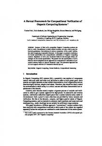
2.1 Where to apply formal Formal verification can often be a resource-intensive endeavor. The first step in developing a formal testplan is to identify which blocks will get a higher ROI from the use of formal verification, and which blocks can be more reliably tested with simulation (directed and random). The discussion in this section will build your background and help you make those decisions. Complexity of formal verification. Formal verification of properties (that is, assertions or requirements) on RTL designs is a known hard problem: the complexity of all known algorithms for formal verification (a.k.a. model checking) is exponential in the size of the designs [1, 2]. Thus, any naïve application of formal verification is likely to cause state-space explosion and impractical computer run-times. One coarse measure of prediction of the tractability of formal verification is the number of state-holding elements (often flip-flops) in the cone of influence of the property (see Figure 1). However, as we will see later in paper, for some classes of designs, this number can sometimes be misleading because reduction techniques (based on the requirements and the design) can dramatically reduce this number. It is imperative that the user prioritize the application of formal verification by choosing design blocks that fall in the sweet spot of formal verification and are amenable to all possible reduction techniques, such as design reduction, abstraction, and compositional reasoning (as discussed further in Section 2.2). Design Block Property
Cone of Influence Irrelevant Logic
Figure 1. Cone of influence
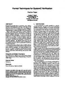
Sequential vs. concurrent designs. A key determining factor for choosing designs suitable for formal is whether a design or block is mostly sequential (that is, non-concurrent) or mostly concurrent. Sequential blocks typically operate a single stream of input data, even though there might be multiple packets at various stages of the design pipeline at any instant. An example of such sequential behavior is an instruction decode unit that decodes a processor instruction over many stages. Another example is an MPEG encoder block that encodes a stream of data, possibly over many pipeline stages. A floating point arithmetic unit is yet another example. Often, you can describe the behavior of a sequential hardware block in pseudo-code in a software language, such as C or SystemC. In the absence of any additional concurrent events that can interfere with the sequential computation, you can adequately test blocks such as these with simulation, often validating against a C reference model. Formal verification, on the other hand, usually encounters state-explosion for sequential designs because most interesting end-to-end properties typically involve most flops of these flop-intensive designs. Concurrent designs deal with multiple streams of input data that collide with each other. An example of such a block is a token generator that is serving multiple requesting agents and concurrently handling returns of tokens from other returning agents. Another example is an arbiter, especially when it deals with complex priority schemes. Both of the previous examples have mostly control flops in the cone-of-influence. An example of a concurrent design that is more datapath-intensive is a switch core that negotiates traffic of packets going from multiple ingress ports to multiple egress ports. While the coneof-influence of such a design can have a large number of flops, especially if the datapath is very wide, a clever use of decomposition can verify correctness of one datapath bit at a time. This process of decomposition (covered more in Section 2.3) effectively reduces the mostly datapath problem to a mostly control problem. Control vs. data transport vs. data transform blocks. Given the discussion above, the following coarse characterization can often help you determine whether formal is suitable. You can usually characterize design blocks as control or datapath oriented. You can further characterize datapath design blocks as either data transport or data transform. Data transport blocks essentially transport packets that are generally unchanged from multiple input sources to multiple output sources, for example, a PCI Express Data Link Layer block. Data transform blocks perform a mathematical computation (an algorithm) over different inputs, for example, an IFFT convolution block (see Figure 2). What makes data transport blocks amenable to formal is the independence of the bits in the datapath, often making the formal verification independent of the width of the datapath. Unfortunately, this kind of decomposition is usually not possible in data transform blocks. The next section lists examples of blocks that are more suited for formal than others.
Design Verification
Control
Datapath
Data Transport
Data Transform
Figure 2. Data verification flow Blocks suitable for formal verification. As discussed, formal verification is particularly effective for control logic and data transport blocks containing high concurrency (illustrated in Figure 3).
Figure 3. Concurrent paths The following list includes examples of blocks ideally suited for formal verification: • • • • • • • • • • • • •
Arbiters of many different kinds On-chip bus bridge Power management unit DMA controller Host bus interface unit Scheduler, implementing multiple virtual channels for QoS Clock disable unit (for mobile applications) Interrupt controller Memory controller Token generator Credit manager block Standard interface (for example, PCI Express) Proprietary interfaces
An example of a bug identified using formal verification on a block involving concurrent paths is as follows: During the first three cycles of a “transaction start” from one side of the interface, a second “transaction start” unexpectedly came in on the other side of the interface and changed the configuration register. The processing of the first transaction was confused by sampling of different configuration values and resulted in a serious violation of the PCI protocol and caused the bus to hang. Concurrent blocks have many of these obscure, timing based scenarios for which formal is well suited. Blocks not suitable for formal verification. In contrast, design blocks that generally do not lend themselves to formal verification tend to be sequential in nature (that is, a singlestream of data) and potentially involve some type of data transformation (see Figure 4).
Figure 4. Non-concurrent paths
Examples of designs that perform mathematical functions or involve some type of data transformation include: • • • •
Floating point unit Graphics shading unit Convolution unit in a DSP chip MPEG decoder
An example of a bug associated with this class of design includes the following: The IFFT block output result is incorrect if both inputs are negative.
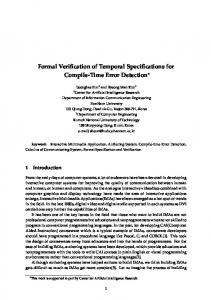
2.2 Formal testplan process In discussing the process of defining a formal testplan, it is helpful to briefly introduce some general concepts of blocklevel formal verification. These introductions are necessarily brief; for additional information refer to Perry and Foster [9], for example. What vs. how. There are two key differences between creating formal and simulation testplans: the strict separation of checks (observability) and input scenarios (stimulus), and the preference of a more general specification style. Unlike simulation, in which checkers and stimulus can be tightly coupled, formal properties are defined in terms of generic behavior, independent of particular input scenarios. Also unlike simulation, formal properties are defined in terms of the minimal correctness criteria. You should avoid cycle accurate behavioral models whenever possible. In certain cases, such as data integrity (see the example in Section 3), the generic nature of formal checks might first appear to require a great deal of scoreboarding state when modeling the requirements. However, effective formal tools should include formal friendly abstractions for these types of properties, thus requiring small numbers of state elements. Compositional reasoning. Compositional reasoning is the process of reducing an analysis of a larger concurrent system to reasoning about its individual functional pieces [8]. This technique is effective for managing proof complexity and state explosion during a formal proof. Compositional reasoning transfers the burden of proof from the global component to the local functional component level so that global properties can be inferred from independently verified functional component properties. One of the main compositional reasoning techniques we successfully use to prove complex designs is referred to as assume-guarantee. This technique calls for you to prove properties on a decomposed block using a set of assumptions about another neighboring block, and then prove these assumptions separately on the neighboring block, as illustrated in Figure 5. assume always !(A & B);
Block X
A
A
B
B
Block Y
assert . . .
Another example of compositional reasoning is formal abstraction, as illustrated in Figure 6. In this case, you prove properties on a subsection of the formal analysis block. Then the driving logic for this subsection is abstracted, that is, the design logic is ignored in favor of the proved properties. This results in a generalization of the design behavior that simplifies the formal analysis. The key point of this technique is that if a property holds on the formal abstractions (the generalization), then it holds on the entire cone of influence (the actual design logic). However, if a property fails on the formal abstraction, then it might be necessary to include additional logic into a larger analysis region, forming a new abstraction that eliminates the false negative. A detailed discussion of formal abstractions is beyond the scope of this paper (for additional details, see [8,9]). Design Block Free Variables Abstracted Inputs
Figure 5. Assume-guarantee
Analysis Region
Property
Irrelevant Logic
Figure 6. Formal abstraction
2.2.1 Formal testplan elements The formal testplan for a design block consists of three components. The first is a set of properties for verification known as requirements or assertions1. In addition, most designs need legal inputs, which are expressed formally in terms of formal properties defined on design inputs and known as constraints or assumptions. Finally, certain test plans might use formal coverage targets. Section 2.4 discusses the meaning of coverage in formal verification.
2.2.1.1 Requirements The first component of the formal testplan is a set of formal requirements. Formal requirements express design behavior to be proved. These are analogous with checkers in simulation environments. End-to-end requirements are assertions expressing the required core behavior of the design, usually across multiple interfaces. Examples of end-to-end requirements are that data are not dropped and that arbitration requirements are satisfied. End-to-end properties should be expressed purely in terms of block interface signals. Interface requirements express the protocol rules expected by neighbor blocks and are expressed purely over a single interface. In general, interface requirements on a block are identical to the input assumptions on the neighboring block on that interface. This is the “guarantee” portion of the assume-guarantee relationship between neighboring blocks. We sometimes collectively refer to end-to-end requirements and interface requirements as high-level requirements. A set of highlevel requirements can express the full specified behavior of the block under verification. However, it might be useful to include a number of assertions related to internal implementationspecific features, that is, local assertions. These internal 1
assert always !(A & B);
Cone of Influence
While there is strictly no difference between these terms, “assertions” is often used specifically to refer to highly localized, implementation-specific properties. For this reason, we favor the term “requirements” for more general use.
properties provide substantial benefits in terms of defect localization and might require relatively little effort to define and verify. Local assertions have been the traditional application for functional formal verification, and we do not discuss them in detail in this paper [10,11].2
2.2.1.2 Assumptions The second component of the formal testplan for a design block is a set of input assumptions. These are formal properties that are generally defined using the same language and semantics as formal requirements. This similarity is essential to the assumeguarantee methodology. Assumptions are necessary to prevent illegal input stimuli from causing spurious property violations. Conversely, incorrect assumptions over-restrict the input stimuli and hide real property violations. Conceptually, overconstraining a proof is similar to running simulation checks with poor functional coverage. In practice however, the situation is different in that it is difficult to measure the effects of overconstrained inputs and nearly impossible to predict them. Tracking and validating assumptions is possibly the most important and subtle part of creating an effective formal testplan. It is often easier to manage assumptions when you use a hierarchical approach to testplan development. You must explicitly state all formal assumptions. The best option is to use assume-guarantee, that is, formally verify each assumption as a requirement on a neighboring design block. Though this option is ideal, in some cases it is not practical for formal verification. As an alternative, you can sometimes validate assumptions from well-specified interface rules, as is the case for a standard interface. If neither of these approaches is practical, you should use assumptions as assertions in higherlevel simulations. Most importantly, all assumptions must be treated explicitly. It is a reasonable expectation for formal tools to provide bookkeeping mechanisms to help track the validity of assumptions. In addition, tools may provide methods for visually sanity testing assumptions. Assumptions have applications other than constraining block inputs. One example is mode setting through mode-related input signal or configuration registers. You will not validate these assumptions in the same sense as interface assumptions. Yet another use for assumptions is to deliberately over-constrain design behavior in preliminary verification.
2.2.1.3 Coverage targets The third component of the formal testplan relates to coverage, specifically, formal coverage targets. Section 2.3 discusses coverage concepts further. In particular, formal coverage properties are a useful test for over-constraining input assumptions.
2.2.2 Verification strategy A complete set of formal properties is one part of a formal testplan; a staged implementation plan is the other part. In particular, when formally verifying a design under active development, organize properties into functional categories and 2
While the completeness of the formal requirement set, as with any set of checks, cannot be guaranteed analytically, a method has been proposed for tools to provide quantifiable guidance (see [5]).
develop a set of increasingly over-constrained assumptions that represent different levels of functional completeness. Verification begins with those properties representing the most basic functionality of the block under the greatest restriction and proceeds to full functionality with no over-constraint. Section 3.1.6 details an example of this approach. A graduated strategy for proving requirements under different levels of restrictions can also be valuable for tracking the progress of formal verification. This is another area in which formal tools can offer useful bookkeeping features.
2.2.3 Hierarchical testplanning In reality, a formal testplan requires something more complicated than a flat list of formal properties for a design block. In general, the ideal block size for formal analysis is not known during the planning stage. In addition, you might target portions of a block or cluster for formal verification even when the block as a whole is not optimal for formal verification. In this case, selecting properties is best viewed from the level of the larger block. You will create formal testplans for large blocks hierarchically, regardless of whether you intend to verify them with formal alone or with a mix of formal and simulation. Initially, you will define the upper-level testplan, which consists of requirements, assumptions, and coverage targets, as if you intend to run the formal analysis at the top level. Then define testplans for each subblock in reference to the top-level testplan and map each toplevel requirement to one or more subblock requirements. Finally, derive subblock assumptions from top-level assumptions and assume-guarantee relationships between subblocks. Within this two-tiered testplan, you will target certain properties for formal verification. If you formally prove the entire block, no simulation is required at this level. In many cases this approach will not be practical, particularly for design organizations that are relatively new to formal verification. If you use simulation for the higher-level block, a clearly organized hierarchical formal verification strategy provides valuable guidance about what simulation checkers to create and what portions of the design you should target with input vectors and monitor with functional coverage points.
2.3 Coverage To conclude our testplan guideline discussion, we must address the concept of coverage. In a traditional simulation verification environment, there are two aspects of coverage you must assess throughout the project to determine the quality of the verification process: input space coverage and requirement coverage. In this section, we describe how these aspects of coverage relate to formal verification. Input space coverage. Input space coverage is a measure of the quality of the input vectors to activate (or exercise) portions of a design. Typically, you can achieve high input space coverage (which is evaluated by metrics such as line coverage or functional coverage) by enumerating various scenarios and creating directed simulation tests to exercise these scenarios. Since it is impossible to enumerate all possible corner-case scenarios for simulation, we generally apply constraint-driven random input stimulus generation techniques to boost simulation coverage.
Formal verification, unlike simulation, does not depend on enumerating corner-case scenarios and then generating input stimulus. In fact, formal verification does not depend on any input stimulus since we explore the entire input space of the design using mathematical techniques without the need for input vectors or simulation. This means that if a property is proven true using formal verification, then there is no sequence of input vectors you can simulate that would expose a corner-case bug. Hence, you do not need traditional coverage techniques (such as line coverage or functional coverage) since the quality of exploring the input space in formal is complete and exhaustive. The risk with formal verification is that a proof might have completed with a set of formal constraints that restricts the input space to a subset of possible behaviors. For formal verification, the coverage you should perform ensures that the design is not over-constrained while performing a proof. Therefore, the extent of coverage is very different from what coverage-driven simulation does. Coverage in a formal verification environment ensures that we do not miss major operations. We demonstrate this process on our example in Section 3. Requirement coverage. The other key aspect of coverage you must consider during verification is requirement coverage (often referred to as property coverage in formal verification). In a traditional simulation environment, you cannot automatically apply any metrics to determine the completeness of the testbench output checkers with respect to the requirements defined in the specification (that is, line coverage and functional coverage metrics do not measure the completeness of testbench output checkers). Hence, when you create a simulation-based testplan, it is critical for the design and verification team to carefully review the requirements identified in the design specification to ensure that an output checker is created to check the set of requirements. In formal verification, you must apply the same process to ensure that the created property set covers all requirements defined in the specification. During this process, there are two questions about the final property set that you must answer: 1.
Have we written enough properties (completeness)?
2.
Are our properties connected (when partitioning complex properties)?
For your design, it is critical for you to review your specification (and your simulation testplan) to ensure that your formal property set covers everything you intend. Concerning the question, “Are our properties connected,” take care when constructing your property set to take advantage of the concept of assume-guarantee (as previously discussed). This approach ensures that any properties used as assumptions on one block will be proved on its neighboring block(s)—thus ensuring the property set is connected and that you can trace a property associated with the output of the memory controller all the way through the design back to its inputs. Achieving high requirement coverage. To ensure comprehensiveness in developing your English requirements checklist, we recommend the following steps: 1.
Review the architectural and micro-architectural specifications and create a checklist of requirements that must be verified.
2.
Review all block output ports in terms of functionality and determine if you need to add items to your requirements checklist.
3.
Review all block input ports in terms of functionality and determine if you need to add items to your requirements checklist.
4.
Review all data input ports and understand the life of the data from the point it enters the block until it exits the block (considering various end-to-end scenarios) and determine if you need to add items to the requirements checklist.
5.
Conduct a final requirements checklist review with appropriate stakeholders (for example, architects, designers, verification engineers).
Measuring verification progress. The formal verification testplan approach provides a direct means to measure progress throughout the verification process. This benefit is easily measured by tracking the English checklist of proved requirements contained within the formal testplan.
3. APPLICATION EXAMPLE In this example, we demonstrate the concepts introduced in Section 2 on a real bridge example.
3.1 Overview AHB-Lite to I2C Bridge "Bridge" is actually a rather broad term that refers to a design where the transport of data (often between different protocols) occurs. In general, data is transferred in one of three forms: •
Direct transfer of data, either as a single-cycle transfer or as a burst
•
A fixed-size cell where there is a header, followed by payload, and finally, some frame-checking sequence
•
A packet, which is similar to a cell in terms of the structure but different in terms of size
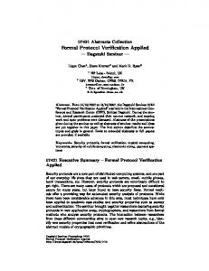
There are several key components in this bridge; however, not all components apply to all bridges. The first key component consists of the interfaces on the two ends of the bridge. The second is the datapath flow through the bridge. The third is an arbiter component (when applicable). Finally, bridges often have some decoding and arithmetic computation, such as CRC calculations and checking, ALU, and so forth. Figure 6 shows an example of a bridge, which is a simple AMBA AHB-Lite [2] to I2C [3] bridge. In our example, the commands flow one direction from AHB to I2C, but the data flows both ways. For the write direction, data are written into a FIFO. When the FIFO is full, the AHB signal HREADYout is deasserted until there is room in the FIFO again. Upon receiving the write data, as long as there is room in the FIFO, the AHB bus is free for other devices sharing the AHB to proceed to their transactions. A read-cycle, however, will hold up the bus until the data is ready (because a SPLIT transaction is not supported by the bridge). Therefore, the read transaction has priority over the write transaction except when there is a coherency issue. For example, if a read address matches the write address of one of the entries in the FIFO, the read transaction must wait until that location is sent before proceeding to the I2C bus. Also, the read
transaction does not interrupt an I2C write transaction that has already started. AHB-Lite Interface
AMBAŖ AHB-Lite
Bridge
I2C
6.
Define verification strategy. This section of the formal testplan is important for listing the strategy used to verify the block. For example, it is important to verify interface requirements before end-to-end requirements. In addition, it might be beneficial to first verify some requirements with restrictions before running with all possible inputs. For example, you might decide to set HWRITE to 1 first. Then proceed to checking the read path by setting HWRITE to 0. Finally, remove the restrictions to allow both read and write.
7.
Define coverage goals. This section is important especially after obtaining a proof. List the coverage points such that if those points are covered, you will be sure the true proof is not a false positive due to over-constraining. Some of the examples of coverage points for this design include FIFO full, completion of read and write on different HSIZE and HBURST, and a read with some occupied FIFO locations.
I2C Interface
Figure 6. AMBA AHB-Lite to I2C Bridge
3.1.1 Challenges in this class of designs Although the gate count for this example bridge is not particularly high, it represents two main formal verification challenges. First, as with many datapaths involving queues, there are storage elements that can cause a large state-space. Second, data-transport paths with queues, and especially involving a serial bus, have a very high sequential depth. Consequently, it is going to take a large number of cycles to complete the proof. Note that although creating a simulation testbench for this example is fairly trivial, simulation suffers the same challenges of dealing with the high sequential depth (that is, a very high number of simulation cycles is required to achieve reasonable coverage).
3.1.2 Example formal testplan process As we previously stated, it is important to create a formal testplan prior to attempting to comprehensively prove a block. For our AMBA AHB–Lite to I2C bridge example, we followed a systematic set of steps to create our formal testplan. In this section, we generalize these steps into what we refer to as the seven steps of formal testplanning, which apply to a broad class of today’s designs. 1.
2.
3.
4.
5.
Identify good formal candidates. First, determine if the block you are considering is a good candidate for formal. (Use the procedure previously described in Section 2.1.) Create an overview description. Briefly describe the key characteristics of the bridge (as we did in Section 3.1). The introduction does not have to be in great detail but should highlight the major functions of the bridge. Define interface. Create a table that describes the details for the block’s interface (internal) signals that must be referenced (monitored) when creating the set of formal properties. You will use this list to determine completeness of the requirement checklist during the review process. Create the requirements checklist. List, in a natural language, all high-level requirements for this block (Use the guidelines previously described in Section 2.3, Achieving high requirement coverage). For our example, this list can be as high-level as separating the requirements into the following functionality: AMBA AHB interface, I2C interface, end-to-end requirements, and miscellaneous requirements, or as detailed as identifying each of the AHB-Lite requirements, I2C requirements, and so forth. Convert checklist requirements into formal properties. In this step, convert each of the natural language high-level requirements into a set of formal properties, using PSL, SVA, or OVL, and whatever additional modeling is required to enable you to describe the intended behavior.
3.1.3 Interface description The following table lists the signals defined in the AMBA AHB-Lite to I2C bridge specification that we chose to monitor as part of our high-level requirements model. Description
Size
Directio n
HCLK
AHB Clock
1-bit
In
HRESETn
Master Reset (active low)
1-bit
In
HADDR
AHB Address
7-bit
In
HBURST
AHB Burst length
3-bit
In
HTRANS
AHB Type
2-bit
In
Signal Name
Transaction
HSIZE
AHB Transfer Size
3-bit
In
HWRITE
AHB Write
1-bit
In
HSEL
AHB Select
1-bit
In
HREADYin
AHB HReady
1-bit
In
HWDATAH WDATA
AHB Write Data
32-bit
In
HRDATA
AHB Read Data
32-bit
Out
HRESP
AHB Response
2-bit
Out
HREADYout
AHB HREADYOUT
1-bit
Out
SDA
I2C Data
1-bit
In/Out
SCL
I2C Clock
1-bit
Out
i2c_clk_ratio
HCLK to I2C Clock ratio
2-bit
In
We find that creating this interface table is a useful part of our formal testplanning process because it provides a clear focus of what needs to be checked from a black-box perspective. Thus it is useful for identifying missing requirements during a formal testplan review (see Section 2.3, Achieving high requirement coverage).
3.1.4 Requirements checklist For our example, there are three main sections of high-level requirements, the two interfaces and the end-to-end requirements. (Listing the full set of requirements is beyond the
scope of this paper.) Our point is to demonstrate the process of creating a comprehensive natural language list of requirements derived from the architectural or micro-architectural specification. AMBA AHB-Lite interface requirements. In general, we can partition AMBA AHB-Lite requirements into two categories: master requirements and slave requirements. For our example, we will focus on the subset of slave requirements. 1. 2. 3. 4. 5. 6.
Slave must assert HREADYOUT after reset Slave must provide zero wait-state HREADYOUT=1 response to IDLE transaction Slave must provide zero wait-state HREADYOUT=1 response to BUSY transaction When not selected, Slave must assert HREADYOUT Slave must drive HREADY low on first cycle of two-cycle ERROR/SPLIT/RETRY response ...
I2C interface requirements. Because of space limitations, we will not list the comprehensive set of I2C interface requirements. However, we list a few I2C requirements below to demonstrate the process of creating a natural language list of requirements: 1. 2. 3. 4.
SDA should remain stable when SCL is high There should not be another start after a start until an end occurs in the I2C bus. The data between a start and an end should be divisible by 9 (8 bit/transfer + 1-bit ack) ...
End-to-end requirements. There are two classes of end-to-end requirements associated with our bridge example. One class includes data integrity requirements. The second class includes consistency requirements, which use data as the golden reference between the formal property and the RTL design to verify that all controls are consistent with the referenced data. For data integrity verification, there are also two separate paths that must be considered, one for read and the other for write. Miscellaneous requirements. Miscellaneous requirements are the checks for read/write dependency and are not included in this paper due to space limitations.
3.1.5 Formal properties Using the interface signals identified in Section 3.1.4, and the set of natural language requirements identified in 3.1.3, create your set of formal properties. We recommend that you encapsulate your set formalized requirements into a high-level requirements model or verification unit that will monitor the block’s interface signals. To demonstrate the formal specification process, we convert the following I2C requirement into both PSL and SVA: There should not be another start after a start until an end occurs in the I2C bus. Figure 7 illustrates the PSL coding for our natural language requirement. In this example, i2c_start and i2c_end represent modeling code associated with the assertion, composed of SCL and SDA. default clock = HCLK; A_no_start: assert (always i2c_start ->
next(~i2c_start until i2c_end)) abort (~RESETn); Figure 7. PSL I2C assertion Figure 8 illustrates the SVA coding for our natural language requirements. property P_no_start; @(posedge HCLK) disable iff (~HRESETn) i2c_start |=> ~i2c_start[*0:$] ##1 i2c_end; endproperty A_no_start: assert property (P_no_start); Figure 8. SVA I2C assertion The process of converting the natural language list of requirements into a formal description is generally straightforward. Hence, we have only illustrated one example of this translation process. At times, in addition to using the temporal constructs of today’s assertion languages, you will need additional modeling (possibly as auxiliary state-machines to model conceptual states of the environment or for capturing data in a scoreboard fashion).
3.1.6 Verification strategy For our example of a formal testplan, the verification strategy section contains two main areas. First is to plan proper partitioning to ensure that we can overcome any verification bottleneck. Second is to provide a set of restriction definitions and the recommended verification steps to systematically loosen these restrictions over the course of the proof. The combination of restrictions and steps forms the methodology used to complete the formal proof on the bridge example. Functional partitioning. It is important to recognize potential bottlenecks in the verification process. Many times you can manage those problems by applying compositional reasoning approaches previously described in Section 2.2. For example, the write data from the input goes through an internal interface to the bridge before being sent out through the I2C interface. There is a potential partition point around the internal bridge. While it might not be necessary to partition the datapath, it is still important to keep this in mind in case performance becomes an issue. For the reverse (read) path, the read request goes directly to the I2C interface—except when there is a conflict with a pending write. Therefore, there must be a conflict detection function to compare the read address against all the write addresses in the FIFO. To include a detection function as part of a datapath requirement not only makes the property overly complex to code, it also adds complexity into the datapath verification. This is because the conflict-checking is a form of decoding logic that is rather complex for formal verification. However, it is rather straight-forward to validate the conflict detection functionality as a standalone requirement, independent of the property. Therefore, it is probably a good idea to separate the datapath verification and the conflict detection verification (by blackboxing the conflict-checking logic). The requirement for the datapath will then use the output of the black-boxed conflictchecking logic as an input during the analysis (assuming all possible combinations of error detection during the proof).
Finally, we verify the conflict-checking logic itself, independent of the datapath property. This way, we partition a difficult problem (data-transport and complex decoding) into two relatively simpler problems. Restriction definition. Formal verification allows you to uncover corner-cases within the design relative to all valid sequences of input values. However, there are occasions when you might want to verify a particular implemented functionality on a partially completed design by restricting the input sequences to a specified mode of operation (for example, explore correct behavior for only read transactions versus read and write transactions). Even under situations where the RTL is complete, but the code has not gone through any verification, it is often more efficient to start the verification process by independently verifying the main functionality with restrictions (that is, a special assumption that restrictions the input space to a subset of possible behaviors). For our example, we divide the requirements into three sets:
Set 1: Input coverage – Read/write access with different burst types, sizes, and lengths, and with HREADYOUT asserted and deasserted. Set 2: Output coverage – Read/write with acknowledgment, no acknowledgement. Set 3: Internal main state-machines – I2C state-machines, AHB state-machines where they can enter and exit each state. Other than coverage that determines whether each coverage point is covered such that there is no over-constraint, it is also important to ensure that the requirements are complete. We go through the steps in Section 2.3 to ensure that there is no obvious hole in the coverage provided by all the requirements. After all the requirements are proven, we also ensure that all the RTL is included in at least one requirement. Otherwise, the codes that are not included are dead-code or additional requirements are needed.
Set 1: AMBA AHB-Lite and I2C interface requirements.
4. CONCLUSION
Set 2: End-to-end datapath, read and write.
In this paper, we proposed a formal-based testplanning process, which includes a systematic set of seven steps. By applying our process to a real AMBA AHB parallel to Inter IC (I2C) serial bus bridge example, we demonstrated that it is relevant to today’s ASIC and SoC designs.
Set 3: Misc. And we define the restriction sets as follows: 1. Only unidirectional access (read or write), single cycle access, no flow-control or errors 2. Only unidirectional access, all burst length, no flowcontrol or errors 3. Bi-directional access, all burst length, no flow-control or errors.
5. REFERENCES [1] A. Aziz, V. Singhal, R. Brayton. ”Verifying interacting finite state [2]
Verification steps. The following lists the recommended steps for proving the AMBA AHB-Lite to I2C bridge example:
[3]
Prove Requirements Set 1 with Restriction Definition 1, Restriction Definition 2, and Restriction Definition 3.
[4]
Prove Requirements Set 2 with Restriction Definition 1, Restriction Definition 2, and Restriction Definition 3.
[5] [6]
Prove Requirements Set 1 with no restrictions. Prove Requirements Set 2 with no restrictions.
[7]
Prove Requirements Set 3 with no restrictions. If the design is mature, such as a legacy code with minor changes, or a design that has gone through some simulation, you might decide to skip through the Restriction Sets 2 and 3. It is still important to go through Restriction Set 1 simply to set up the proper environment and constraints, but it is not necessary to go through the other restriction sets.
3.1.7 Coverage As mentioned previously, coverage for formal verification serves a different purpose than that in simulation. The coverage points should focus on ensuring no over-constraining at the inputs. Therefore there are three sets of coverage points:
[8] [9] [10] [11]
machine: complexity issues.” Technical Report UCB/ERL M93/52. Electronics Research Lab, Univ. California, Berkeley, CA 94720. AHB - AMBA Specification (rev 2.0) by ARM, copyright ARM 1999. I2C - The I2C-Bus Specification Version 2.1 January 2000 by Philips Semiconductors. IEEE Standard for Property Specification Language (PSL), IEEE Std. 1850-2005. IEEE Standard for SystemVerilog: Unified Hardware Design, Specification and Verification Language, IEEE Std. 1800-2005. J. R. Burch, E. M. Clarke, K. L. McMillan, D. L. Dill, L. J. Hwang. “Symbolic model checking: 1020 states and beyond. Information and Computation,” 98(2):142-170, 1992. K. Claessen. “A coverage analysis for safety property lists.” Unpublished manuscript. April 2003. http://www.cs.chalmers.se/~koen/Papers/coverage.ps K. L. McMillan. “A methodology for hardware verification using compositional model checking.” Science of Computer Programming, vol. 37, no. 1-3, May 2000. D. L. Perry, H. Foster. Applied formal verification. McGraw-Hill, 2005. J. Richards, D. Phillips. “Creative assertion and constraint methods for formal design verification.” In Proceedings of DVCon, March 2004. P. Yeung. “The four pillars of assertion-based verification.” In Proceedings of EuroDesignCon, October 2004.