Because of these there is a need to introduce formal methods in the ... In this report we study the integration of formal methods applied on a health care case.
A Methodology for integration of formal methods in a healthcare case study Luigia Petre, Elena Troubitsyna, Marina Waldén*, Pontus Boström, Niklas Engblom, Micaela Jansson Åbo Akademi University, Department of Computer Science, Lemminkäisenkatu 14, FIN-20520 Turku, Finland *
Financed by the Academy of Finland
Turku Centre for Computer Science TUCS Technical Report No 436 December 2001 ISBN 952-12-0939-9 ISSN 1239-1891
Abstract When developing safety-critical systems, it is necessary to satisfy not only functional requirements defining the set of tasks to be performed by the system, but also safety requirements describing the characteristics the system should possess in order to ensure proper safety. Reliability is, as well, an acute issue in the development of safety-critical systems. Enhancement of safety and reliability can be achieved by applying formal methods, while complexity of large systems can be mastered using a graphical language for modelling, e.g., UML. Here we introduce a UML-based development process that incorporates safety analysis and provides a logical interface to a formal refinement based development in B-action systems. The tools associated with the B Method provide a good mechanised support for proving the correctness of the development within B-action systems. We show the feasibility of our development process within a healthcare case study where we develop a safety-critical drug discovery system. The work has been done within the EU-project MATISSE - Methodologies and Technologies for Industrial Strength Systems Engineering (IST-1999-11435, http://www.matisse.qinetiq.com/).
Keywords: Formal Methods, Safety Analysis, UML, Action Systems, the B Method
TUCS Research Group Programming Methodology Group
1. Motivation for using formal methods While developing safety-critical systems, it is necessary to satisfy not only functional requirements defining the set of tasks to be performed by the system, but also safety requirements describing which characteristics the system should possess in order to ensure proper safety. Safety and reliability are acute issues for these systems under construction [Storey96, Troubitsyna00]. Reliability means the correct functioning of the system under a given set of operating conditions. It constitutes one of the most important properties that, for example, the drug discovery systems and the biomedical research should provide. Reliability should guarantee an extremely high precision and the constant level of quality of experiments to be performed. The need to achieve these requirements introduces specificity in the typical process of development of a control system. Safety is the property of a system which ensures that it will not harm humans, environment or equipment. According to the classifications normally used in safetycritical systems the severity of the direct harm to the humans using a drug discovery systems is quite moderate. However, the indirect harm caused by the results of incorrectly performed experiments might be catastrophic. The results of failures of such a system might also lead to significant economical losses. Hence, the system is both safety and money critical. Enhancement of both safety and reliability can be achieved by applying formal methods. In the past few years regulatory requirements for drug discovery systems have tightened. Because of these there is a need to introduce formal methods in the development lifecycle to prepare for the future regulations. Also the competition in the field constantly requires shortening the marketing window. Since the application of formal methods allows early error discovery, formal methods could speed up the development process. A software development method that is industry-driven and in fact has become the ‘de facto’ software-modeling standard is UML (the Unified Modeling Language). UML is a graphical language for specifying, visualizing, developing and documenting software-intensive systems [UML1.4]. It encompasses good engineering practices that have proven successful in the modeling of large and complex systems. Complex distributed systems are favourably developed by stepwise adding details to the system. The B-action systems is a formalism for supporting this kind of development of distributed systems [BW96,WS98]. The formalism uses stepwise refinement for developing a system correct by construction. Each refinement step is
1
accompanied by proofs. The B Method [Abrial96] and its associated tool provide us with a good mechanised support for refinement based development. The B Method has already been successfully used in industrial projects.
2. Formal development of the healthcare case study In this report we study the integration of formal methods applied on a health care case study. We introduce a UML-based development process that incorporates safety analysis and interfaces with a formal development in B.
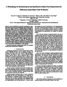
2.1 Presentation of the Wallac case study PerkinElmer Life Sciences designs, manufactures, develops, and markets analytical systems for use in drug discovery, mass population screening, and other bioresearch and clinical diagnostics areas. PerkinElmer Life Sciences was formed from the international Wallac Group, and is today a worldwide organization with about one thousand employees. PerkinElmer Life Sciences (later in the document referred to as Wallac) supplies complete analytical systems. The systems are used to provide researchers and clinicians with reliable determinations of ‘difficult to measure’ substances found in blood or other biological sample materials. Typically, the substance to be measured is tagged with a radionuclide or a fluorescent or luminescent label. The amount of the substance is then determined from the ‘signal’, or the amount of radiation or light given off by the label. The manufactured analytical systems include reagents, sample handling and measuring instrumentation, as well as computer software. The team of the Computer Science Department at Aabo Akademi University (later in the document referred to as Aabo Akademi) is conducting a parallel development of a new product of Wallac’s – Fillwell™, a workstation preparing samples [PerkinElmer01]. The workstation is shown in Fig. 1. The system belongs to the class of products for drug discovery and bioresearch. The Fillwell microplate liquid handling workstation offers significantly advanced features in the line of the sample preparation systems. The Fillwell base unit consists of a dispense head dispensing liquid into microplates on a processing table. A gantry moves the dispense head with high precision and speed from one plate to another.
2
Fig. 1: The Fillwell microplate liquid handling workstation. The Fillwell workstation is the first liquid handling system specifically designed for high density microplates. The system is modular and can therefore be customized into a variety of configurations. The dispense head can have up to 384 tips attached. With the tips the head can perform automated pipetting into plates with 96, 384 or 1536 wells. The head provides a precise dispensing with volumes from 0.5 to 300 µl. The processing table contains up to 6 plate positions. An extension with three plate positions is easily removable. In Fig. 1 this processing table extension has been removed. In order for the dispensing head to be able to reach all the positions on the processing table it is mounted on a gantry that can move in XYZ-directions. The precision of the gantry is very high with an accuracy of 100 µm. The system can function as a standalone workstation or be integrated into a robot. The main application of the Fillwell workstation is drug discovery. Within this application area the system can be used for microplate replication, for dilution, transfer and addition of the liquid in the plates, for reformatting of plates with different densities (number of wells), as well as for rapid plate filling to homogenous and cell based systems. The FillWell system is a safety-critical system. Safety is the property of a system, which ensures that it will not harm humans, environment or equipment. The direct harm to the humans using the drug discovery systems is quite moderate according to the classification for normal safety-critical systems. However, the indirect harm caused by the results of incorrectly performed experiments might be catastrophic. Furthermore, the system can be used to handle extremely expensive substances (valued up to a billion EURO per kg) as well as serve as a part of an expensive production chain. Hence, failures of such a system might result in significant economical losses and the system can also be considered as money critical.
3
2.2 The setting of the case study The case study is organised using an industry-as-laboratory approach. This means that the researchers in academia provide the formal methods and B expertise while the experts at the R&D department of the industrial partner bring the domain knowledge to the team. In order to come up with a good methodology for the development we started with a smaller part of the case study concentrating on modelling the dispense head and its movement up and down as well as its dispensing of liquid. However, the branch of development of medical and pharmaceutical equipment is highly competitive. Because of that, the requirement to preserve confidentiality of the equipment under construction was very strict. As the product has been confidential until recently (mid September) we have developed a mirror case study, called the Robot analyser, in order to have a public case study as an example of the methodology. We have chosen a mirror case study that models the significant and critical aspects of the Fillwell case study concerning the precision of movement and liquid handling. Both the case studies belongs to the same class of systems. In the Fillwell case study we have a workstation dispensing to and aspirating from plates. Our mirror case study is a robot analyser that analyses samples on a plate that is placed on a movable operating table. The movement of the operating table corresponds to the movement of the dispense head, while the analysing corresponds to the dispensing. A first extension of the systems would be to take into consideration the XY-movement of the dispense head and, hence, the corresponding rotation of the robot to be able to work with more than one plate.
2.3 The requirements of the case study The Robot analyser consists of two interacting parts, a Robot and an Analyser. We concentrate here on the Analyser. The task of the Robot is to place a plate to be analysed into the Analyser, as well as to remove an analysed plate from it. The Analyser has an operating table – a horizontal surface on which a plate is placed by the Robot. The Analyser can move its operating table to pick up a plate from the Robot, move the table to its analysing component, analyse the plate, as well as move the table to a position from which the Robot can remove the plate. During the analysis it is checked that there is enough liquid on the plate before the analysis and that the right amount of liquid was used during the analysis. The quality of the analysis should be kept at a constantly high level.
4
The Robot has two arms, one for placing a plate in the Analyser and the other for removing this plate. These arms are at different heights. Therefore, the table has to be at different positions for placing and removing plates: Upper end position: A plate is analysed by the analysing component Middle position: Arm 1 of the Robot places a plate into the Analyser Lower end position: Arm 2 of the Robot removes a plate from the Analyser Initially the Analyser is at its middle position and it is empty. Due to the fact that the operating table and the Robot arms may collide we define the following safety requirements: - When the Robot is ready to load the Analyser, arm 1 may extend only if the table is in its middle position. - When the Robot is ready to unload the Analyser, arm 2 may extend only if the operating table is in its lowest position. - The table may move only when the respective Robot arm has retracted. - The table must not move beyond its upper and lower end position. During a typical course of events the following sequence of actions happens with a plate. Here, we have not considered the possible failures. 1) The Analyser moves the operating table to the middle position (move(zmid)). 2) The Analyser waits to receive a plate from the first Robot arm after the Robot has picked up a plate and rotated to the Analyser (receive). 3) The Analyser moves the operating table to the upper end position (move(zmax)). 4) The Analyser analyses the plate (analyse). 5) The Analyser moves the operating table to the lower end position (move(zmin)). 6) The Analyser waits to deliver an analysed plate to the second Robot arm and the Robot rotates to pass the plate on to another device (deliver). We can note that other courses of events are possible depending on in which order the commands move, receive, analyse and deliver are given. In order to prohibit the Analyser to analyse a plate and move an infinite number of times, only a certain number of moves are allowed to be performed in a row before some other action need to be taken by the Analyser. Similarly, only a certain number of analyses on one plate are allowed before the plate has to be delivered.
5
2.4 The integrated development process proposed for the case study The core idea of our overall development process is based on applying both safety analysis and B reasoning about correctness to an already constructed UML specification of the eventual control system. Usually such a specification is neither obvious, nor simple to obtain for a large and complex final system, given only the initial informal requirements. Hence, a more scalable approach is required for producing at least the first specification of the system. The initial specification should already ensure safety and be proved to be consistent. We elaborate on the initial specification by introducing functionality details in a stepwise manner. The correctness of the refinement of the initial specification into a specification incorporating these details is proved using the B-action systems. In each refinement step, safety properties of the system are preserved. The entire development process also requires a consistent documentation strategy that enables smoother evolution and reuse of the produced system. UML provides us with such documentation means at every stage of the development process. When developing control systems the final detailed system is decomposed into a plant, a controller, sensors and actuators [PRTWJ01]. Hence, our development process comprises two main phases. First, a system specification is developed from the initial informal requirements. Second, upon proving its consistency with these requirements, the specification is stepwise refined into a concrete, more detailed system using the B-action systems. Safety and reliability considerations are incorporated into the entire process.
3
Safety aspects of the development
The development process should ensure safety and reliability of the system under construction. Therefore, we need to incorporate safety analysis in the existing development process. Only if safety and reliability attributes are considered from the early stages of the system development, the required dependability of the system can be achieved.
3.1 Hazard Analysis The safety requirements result from safety analysis, which includes hazard analysis, assignment of dependability attributes and assessment of system criticality [Leveson95, Storey96]. Handling of hazards plays a paramount role in safety analysis. A hazard is a state of the system that, together with other conditions in the
6
environment of the system, leads inevitably to an accident [Leveson95]. Hazard analysis allows the designers to identify the potential danger associated with a system. It includes hazard identification, classification and decision on methods required to handle the hazards. The identified hazards are distinguished by risks associated with them. The concept of risk combines the severity and frequency of a hazard [Storey96]. The severity of a hazard is a measure of the consequences of an accident caused by this hazard. The identification of the hazards associated with a system and their classification provide information for finding the appropriate methods for dealing with the hazards. Hazard analysis supplies also more information regarding routine system behaviour, behaviour in presence of failures, failure modes of system components. This information provides a basis for the assignment of the appropriate dependability attributes as well as the level of criticality (dependability) to the system under construction. The higher the level of system criticality, the more rigorous the design methods.
3.2 Safety analysis within software development Nowadays, software is used in the vast majority of safety-critical systems. Therefore, the design of embedded software plays an important role in development of dependable systems. Obviously, the software used in safety-critical applications cannot of itself produce any direct harm to the controlled environment. It is the equipment being incorrectly controlled by software, which causes harm directly. We argue that program refinement constitutes a suitable approach to the development of correct software for safety-critical applications. While designing software for safety-critical systems, it is necessary to consider the possible safety implications, i.e., to ensure that the suggested design does not introduce additional hazards. Moreover, we should ensure that controlling software reacts promptly on hazardous situations by trying to force the system back to a safe state. Clearly, this goal can be achieved only if the information provided by safety analysis is taken into account in the process of software development. We propose an approach for conducting software development hand-in-hand with safety analysis as presented in Fig 2. We observe that both the safety analysis and the stepwise program development conduct reasoning from an abstract level to a concrete level. Safety analysis starts by identifying hazards that are potentially dangerous, and proceeds by producing detailed descriptions of them together with finding the means to cope with these hazards. We as other researchers [Leveson96] argue that only if
7
safety and reliability attributes are considered from the early stages of the system development, the required dependability of the system can be achieved.
Safety analysis Functional requirements
Safety requirements
Abstract specification
Elaborated safety analysis Elaborated safety requirements
Refined specification
…
Safety analysis implementation
Elaborated requirements
of
safety
Implementation
Fig. 2: Safety analysis and stepwise system development The refinement process starts by producing an abstract specification describing what should be done rather than how it should be done. Each refinement step allows us to incorporate more implementation details in the abstract specification, so that we end up in a program. Therefore, we can incorporate the information that becomes available at each stage of the safety process by performing corresponding refinements of the initial specification. Hence, in the Analyser development the safety analysis will be woven into the UML- and B-action systems development as will be seen in the following sections.
8
3.3 Dependability impairment A safety-critical system is usually a control system with a computer-based controller managing a plant. There are two main entities involved: an environment and a controller. While developing a specification for a control system, we model the behaviour of the overall system, that is, the physical environment and the controller together. In report [PRTWJ01] we elaborate more on control systems. This allows us to state explicitly the assumptions that we make about how the environment behaves. By specifying the overall system we can abstract away from means of interaction between the controller and the plant (via sensors and actuators) and, as a result, obtain more succinct initial specification. At the later stages of the development process, when the desired level of detail is achieved, we separate the controller and the plant, thus, obtaining the specification of the controller as such. The plant behaviour evolves according to the involved physical processes and the control signals provided by the controller. The controller observes the behaviour of the plant and adjusts it to guarantee intended plant functionality. While observing the plant behaviour the controller reacts on certain events requiring its intervention. Hence, that kind of system is a typical example of a reactive system.
3.4 Presence of failures The controller bases its decision on the information that it obtains from sensors. Due to faults of the system components and imprecision of the sensors, the controller obtains an approximation of the equipment state rather than a real state. Failure occurrences deteriorate this approximation and potentially lead to dependability impairment by: - loss of precision in the function execution, i.e., a decreased reliability of the system, - system failure as a result of violation of safety, - complication in synchronizing the involved machines (which has implications for both safety and reliability). Therefore, handling failures constitutes an important aspect in developing safetycritical systems.
3.5 Handling failures In order to build a controller able to withstand components failures the following actions are required:
9
• • •
to understand the nature of faults and their impact on the overall system, to decide on the detection procedures, repair procedures, functioning of the system in presence of failures, to introduce an effective maintenance procedure.
To incorporate the results of safety analysis in a systematic way in the refinement process the following methodological aspects should be addressed: o Modeling fault occurrence o Modeling fault detection o Modeling system behavior in presence of faults o Modeling synchronization in presence of faults o Modeling different operating modes and transition between modes including the system failure o Design and specification of a maintenance procedure: analysis of additional safety percussions during maintenance, specification of system behavior in the manual mode o Specification of the execution log These actions of handling failures are taken in the UML- and B-action systems development described in the following sections.
4. UML-development incorporating safety aspects The starting point of a system development is an informal specification describing the services desirable from the eventual product, with no or few hints about the various software and hardware parts. We consider this to be the most general starting point for the development process of a control system. The most important role is played by UML in the first phase of the process, when a system specification is determined from the initial requirements. We define a method for using the UML diagrams for designing a control system specification [PS00]. An essential contribution at this level is the embedding of the safety analysis within the UML method. We depict the informal requirements of the healthcare case study with UML diagrams. The functional requirements of the system are captured together with their relationships in a use case diagram. The reliability and safety issues are given in the specification of the use cases as structured English text. Then the logically related use cases are determined, and grouped together into a control system component in component and class diagrams. The behaviour of the component is specified with a statechart diagram. The informal specification of the eventual system is thus gradually captured and made more and more precise throughout these diagrams.
10
4.1 Functional requirements capturing safety issues The functional requirements of the system are depicted, together with their relationships in a use case diagram as presented in Fig. 3. Each use case expresses a service that the system will eventually provide to a user. In Fig. 3 we have a system with three use cases.
Fig. 3: A use case diagram To exemplify the integrated methodology we create the controlling software for an analysing device, here called the Analyser. The Analyser is restricted to move vertically and to analyse blanks/plates. The simplified operations form the protocol of the analysing device. This protocol is described below. A typical protocol can be as follows: 1) Move to middle position 2) Receive plate 3) Move to upper end position 4) Analyse the plate 5) Move to lower end position 6) Deliver plate 7) Repeat from step 1. Hence, the functional requirements of the Analyser is to analyse plates, to receive plates from and deliver plates to the Robot and to move the operating table to its three possible positions. A use case diagram of the Analyser is given in Fig. 4. The Robot and the Analyser interact by the Robot loading a blank to the Analyser receiving it, as well as by the Robot unloading a blank from the Analyser delivering this blank. The Robot is the active partner while the Analyser is the passive partner during this interaction.
11
Fig. 4: Use Case Diagram for the Analyser. Besides these functional services we also capture, at a reasonable level of detail, the reliability and safety issues related to the determined functional services. These issues are not captured in the diagram, but in the specification of the use cases, most commonly expressed as structured English text. Hence, at this level the vocabulary of the whole system is fixed, an overview statement is defined, and the goals, attributes and basic functions, as well as their possible deviations are all captured by careful systematic analysis. The Analyser in our example is seen as a small part of the whole system.
Goals We consider the following goals for the operator and user (as in Fig. 3) of the whole system in our case study. 1) Easy operation of the whole assembly by humans. 2) Fast and accurate control of the mechanical parts. 3) Fast and accurate analysis of the protocol results. 4) Automatic inventory of the processing operations (perhaps stored in a log). 5) Careful functional and safety analysis for simulating the protocol of the Analyser operation. The first four goals are common to the whole project and refer to the eventual software. The fifth goal refers essentially to the process of producing the eventual software. We apply a combination of formal methods (the B Method and B-action systems), UML and safety analysis for checking the quality of the eventual software and for producing this software, which we could then claim to be correct. This fifth goal is the most important to us.
12
Basic functions The basic functions for the eventual software of the healthcare case study are as follows: 1) Capture the protocol information when entered. 2) Communicate the protocol information with the mechanical parts. 3) Record the running protocol. 4) Inform about failures and the failure points. These are the functions we have identified for the controlling software of the system. In this case study we are only interested in functions 1, 2 and 4. We assume that the position detection of the operating table is absolutely reliable in the Analyser. The risks and dependencies of the system are listed during the development process.
Use cases incorporating the possible failures We have identified four use cases, move, receive, analyse as well as deliver for the Analyser as shown in Fig. 4. We consider these use cases as subroutines, since it is more convenient with subroutines for the purpose of safety and reliability analyses. Subroutine Move captures the moving of the operating table to the position pos. Typical course of events: 1. Analyser receives command move to position pos from protocol. 2. System checks if pos is a valid position; if not, then MF1. 3. System checks if it is safe to move; if not then MF2. 4. System checks if current_pos /= pos and if further moves are allowed; if not then MF3. 5. Analyser moves to position pos. 6. System checks if current_pos = pos; if not then MF4. 7. Signal move_ok. Failure reports: MF1. Input parameter pos is outside the valid range. Remedy: User changes parameter pos, identifies the cause and resumes or aborts calling protocol execution. MF2. Robot is not safe. Remedy: Wait a while for the Robot to become safe. MF3. Erroneous move command. Protocol failure. Remedy: Check and change protocol or abort. MF4. Analyser has not reached position pos. Remedy: Calibrate and resume or abort calling protocol execution 13
Subroutine Receive captures the analysing of a plate from the Robot, provided the operating table is at its middle position and there is no plate in the Analyser. Typical course of events: 1. Analyser receives command receive from protocol. 2. System checks if Robot has a plate available; if not then RF1. 3. System checks if current_pos = middle position to Receive; if not RF2. 4. System checks if the Analyser is empty; if not then RF3. 5. Robot loads the Analyser. 6. System checks if plate has been received; if not then RF4. 7. Signal receive_ok. Failure reports: RF1. Robot is not ready to load the Analyser. Remedy: Wait a while for the robot to become ready. RF2. Current_pos /= middle position to Receive. Remedy: User identifies the cause and moves the Analyser manually. RF3. Plate is present. Remedy: User identifies the cause, and unloads the Analyser manually or aborts. RF4. The Analyser has not been loaded. Remedy: User identifies the cause, loads the Analyser manually and resumes or aborts. Subroutine Analyse captures the receiving of a plate from the Robot, provided the operating table is at its upper end position and there is a plate in the Analyser. Typical course of events: 1. Analyser receives command analyse from protocol. 2. System checks if a plate is present in the Analyser; if not then AF1. 3. System checks if current_pos = upper end position to Analyse; if not AF2. 4. System reads the amount of liquid on the plate; if not enough liquid to perform the analysis AF3. 5. Analyser performs the analysis if still allowed to analyse; if not then AF4. 6. System reads the amount of liquid on the plate; if the analysis was not performed ok then AF5. 7. Signal analysis_ok. Failure reports: AF1. No plate is present in the Analyser. Remedy: User loads the Analyser manually and resumes or aborts. 14
AF2. Current_pos /= upper end position to Analyse. Remedy: User moves the Analyser manually to upper end position and resumes or aborts. AF3 There is not enough liquid on the plate. Remedy: User finds out the reason of the situation and resumes or aborts the calling protocol. In case of resuming: user manually loads liquid and resumes protocol. AF4. Erroneous analysis command. Protocol failure. Remedy: Check and change protocol or abort. AF5. Failure in analysis, the analysis did not use the right amount of liquid. Remedy: User initiates a maintenance procedure to fix the pump precision. After maintenance user resumes or aborts protocol. Subroutine Deliver captures the delivering of a plate to the Robot, provided the operating table is at its lower end position and there is a plate in the Analyser. Typical course of events: 1. Analyser receives command deliver from protocol. 2. System checks if Robot is ready for plate; if not then DF1. 3. System checks if current_pos = lower end position to Deliver; if not DF2. 4. System checks if a plate is present; if not then DF3. 5. Robot unloads the Analyser. 6. System checks if plate has been delivered; if not then DF4. 7. Signal delivery_ok. Failure reports: DF1. Robot is not ready to unload the Analyser. Remedy: Wait a while for the Robot to become ready. DF2. Current_pos /= lower end position to Deliver. Remedy: User identifies the cause and moves the Analyser manually. DF3. Plate is not present. Remedy: User identifies the cause, and loads the Analyser manually or aborts. DF4. The Analyser has not been unloaded. Remedy: User identifies the cause, unloads the Analyser manually and resumes or aborts. Failures: From the alternative courses of events above we can derive the following failures: a) Analyser move failure b) No plate present c) Plate already present 15
d) Analysis failure e) Robot rotate failure f) Robot arms move failure g) Robot arms gripper failure h) Protocol failure Upon having this reasonably grained use case based specification, the next step is to determine the logically related use cases, and group them together. Each group of related use cases defines (informally still) a control system component.
4.2 Component-oriented development Component-oriented development consists of reusing existing components, developing new components, and assembling new systems from them. A component is usually defined as a black box implementing a set of services, provided that the required set of context dependencies are available. A component is thus an abstraction over the space of services of a system. The services that a system has to perform, captured by the use case diagram, are partitioned into groups, each group of services being eventually implemented by a component. Components interact with each other by using the provided services. Thus, an important issue regarding a component-based system is the interactions among the participating components as shown in Fig. 5.
Fig. 5: Components By defining a set of components of the final system we distribute the computation already in this early development stage. The strategy of separating computation and communication from the beginning supports well reuse and scalability. A subset of the eventual system components may already exist and can be reused. Each of the unimplemented components is a self-contained system of finer granularity than the initial system. Therefore, the process of specifying a system is reduced to specifying 16
each defined, but not yet implemented component, encompassing the communication means with other components. The resulting specification models the necessary conceptual model of the component required for providing the component services. The component diagram is deduced from the use case diagram, and the component interactions are deduced from the use case relationships. Each use case can be mapped to a component service. While the use case diagram shows only the required services and their relationships, the component diagram distributes the services to a set of components that will implement them. The conceptual model of each component, required for providing these services, is typically specified in a precise manner, using a certain specification language. We use the B-action systems to express the component specifications. Each component is modeled as one or more machines within the B Method. The services of the component are operations in the machine. In our case study the functional requirements of the Analyser are to receive plates which are being analysed and then delivered to an external device, the Robot. From the use case diagram in Fig. 4 we can construct an associated component diagram as given in Fig. 6. We are only interested in the Robot loading and unloading the Analyser. The rest of the services of the Robot are only given as ‘other services’.
Fig. 6: A Component Diagram for the analysing device.
4.3 Statechart diagrams At this level, the conceptual model of the component is shown as one active class, i.e., a class whose instances have autonomous behavior. The class has typically several attributes and methods and the autonomous behavior is specified using statechart diagrams. At least three such statechart diagrams are developed. The first primitive statechart diagram is shown in Fig. 7. The services in this statechart diagram are derived from the services in the use case diagrams. Here we merely model state transitions and events causing these transitions. We go from state 17
Idle to a service n or to state Suspension. After service n is performed we return to state Idle or go to state Suspension. From state Suspension we may return to service n or to state Idle, or go to the state Abort. An attribute named state is added to the component's class to model this behaviour.
Fig. 7: A basic statechart diagram for a component. The basic statechart diagram of the Analyser in Fig. 8 can be derived from the use case diagram in Fig. 4. The services move, receive, analyse and deliver in the use case diagram form the states in this basic statechart diagram together with the states idle, suspended and abort.
18
move
[not_ok]
mv_cmd Remedy
[ok]
deliver
[not_ok]
del_cmd Remedy
[ok] start
[not_ok] suspended
idle
No_Remedy
abort
Remedy rec_cmd
stop
[not_ok]
[ok]
Remedy
receive
anal_cmd [ok]
[not_ok] analyse
Remedy
Fig. 8: Basic Statechart Diagram for the Analyser. Next we state the services of the basic statechart with more details in a refined statechart diagram. The refined statechart diagram presented in Fig. 9 shows the component evolving from a state Idle to states performing each of the required services, provided certain conditions, ServiceN_prec, are satisfied. If these services are successfully performed, when ServiceN_postc holds, the component returns to its state Idle. An exception of a service suspends the autonomous behavior of a component, that evolves to the state Suspension. If a remedy of an occurred exception is found, the component can resume its service-providing state. If no remedy exists, then the exception is a failure and the component aborts its execution. The refined statechart diagram is derived from the use case description (subroutine description). All the conditions shown in the diagram are expressions on the class attributes and methods. At this level, the initial informal specification regarding the respective component is completely captured by this refined statechart diagram. This diagram can still be refined to a more detailed statechart diagram involving more attributes and methods.
19
Fig. 9: A refined statechart diagram for a component
A refined statechart diagram of the Analyser can be found in Appendix A. All the subroutines are pictured in this statechart diagram. In order to be able to get a better overview of each subroutine and to capture all the details we would need a separate statechart diagram for each subroutine. The connection between these separate diagrams would then need to be explicitly stated. This is still ongoing work within the healthcare case study.
5. B-action systems in the development While we can guarantee the consistency of the first statechart diagram in Fig. 7, due to its basic patterns and simplicity, a more complex diagram is not obviously shown to be consistent with its specification. For ensuring this, we need a formal analysis tool. A formal method that comes with such tools is the B Method. We rely here on one of the tools supporting it, Atelier B, when performing the development and the proving. In order to be able to reason about distributed systems within the B Method we use B-action systems [WS98] related to Event based B.
5.1 The abstract specification The first step in our formal development is to create an abstract B-action system from the basic statechart diagram in Fig. 7. The tool U2B [SB00] developed within the MATISSE project at Southampton University supports this translation. The event triggering state transitions (names assigned to arrows) correspond to operation names in the abstract machine specification below.
20
MACHINE Component VARIABLES state, cmd INVARIANT state : {Idle,Service1,Service2,Service3,Suspension,Abort} /\ cmd : {serv1,serv2,serv3} INITIALISATION state := Idle || cmd :: {serv1,serv2,serv3} OPERATIONS New_command(ss) = PRE ss : {serv1,serv2,serv3} THEN SELECT state = Idle THEN cmd := ss END END; Service1 = SELECT cmd = serv1 /\ state = Idle Service1_fail =
THEN state := Service1 END; SELECT cmd = serv1 /\ state = Idle THEN state := Suspension END;
Service1_ok = SELECT state = Service1 THEN state := Idle END; Service1_notok = SELECT state = Service1 THEN state := Suspension END; … Service_notready = SELECT state = Idle THEN state := Suspension END; Remedy = Failure =
SELECT state = Suspension THEN state :: {Idle,Service1,Service2,Service3} END; SELECT state = Suspension THEN state := Abort END
END
The B-action system is identified by a unique name, C o m p o n e n t. The attributes/variables of the system are given in the VARIABLES-clause. In the basic statechart diagram the attribute state and the attribute cmd corresponding to ServiceN form the variables of the system. The types and the invariant properties of the local variables are given in the I N V A R I A N T -clause and their initial value in the INITIALISATION-clause. The operations/services on the variables are given in the OPERATIONS-clause. Each service of the basic statechart diagram will have four operations: the first for checking its precondition, the second for taking care of a false precondition, the third for executing the proper result of an operation and the fourth for taking care of a failed computation. We also have an operation Remedy for fixing an exception and continuing the computation, and an operation Failure taking the system to the state Abort from where no further execution is possible. With this B-action system we model parallel and distributed systems, where operations are selected for execution in a non-deterministic manner. The operations are given in the form Oper = SELECT P THEN S END, where P is a predicate on the variables (also called a guard) and S is a substitution statement. When P holds the operation Oper is said to be enabled. Only enabled operations are considered for
21
execution. When there are no enabled operations the system terminates. The operations are considered to be atomic, and hence, only their input-output behaviour is of interest. In B-action systems we can also have global variables that can be read and updated by more than one system. The global variable is declared in a separate machine Global_z which is INCLUDED in the communicating systems A_comp and B_comp. By including the machine Global_z in A_comp and B_comp, they are both allowed to assign a value v to the variable z via the operation assign_z(v) [WS98]. MACHINE A_comp INCLUDES Global_z VARIABLES … END MACHINE B_comp INCLUDES Global_z VARIABLES …
MACHINE Global_z VARIABLES z INVARIANT J(z) INITIALISATION z := z0 OPERATIONS assign_z(v) = PRE J(v) THEN z := v END END
END
Previously developed machines that have been shown correct can be used in the development by including them in the component using SEES, INCLUDES or EXTENDS [Abrial96]. We can also have procedures in a B-action system. The procedures declared in a B-action system can be local or exported. The local procedures are declared and referenced locally within the same system. The exported procedures, on the other hand, may be referenced by other B-action systems as well. An exported procedure of one system is an imported procedure of another system. The exported/imported procedures are services provided/claimed between systems (components) and can be derived from the component diagram. Let us consider the exported procedure P declared in system B_comp and called from system A_comp as shown below. MACHINE A_comp
MACHINE B_comp
INCLUDES B_comp VARIABLES
VARIABLES y
x
INVARIANT
INVARIANT I(x)
J(y) INITIALISATION
INITIALISATION x := x0
y := y0 OPERATIONS
OPERATIONS A1 = SELECT Q1 THEN T1 || P END;
P = SELECT G THEN U END; …
…
END
END
22
We note that the B Method requires the calling operation and the procedure to be in separate machines. Hence, in case an operation in B_comp also calls the procedure P, we have to outsource P into a separate machine and incorporate them via the INCLUDES -clause. When operation A1 calls procedure P, A1 is enabled only if procedure P is also enabled, i.e., Q1 /\ G holds. The procedure P and the operation A1 are executed as a single atomic entity. The procedures are discussed in more detail in [Waldén98].
Formal specifications and safety analysis Our initial specification of the system is rather abstract – it merely models transition between states. However, already in the initial specification we reserve a possibility of fault occurrence and system failure. The actions Service1_fail and Service1_notok model failure of execution of command. Service1_fail =
SELECT cmd = serv1 /\ state = Idle THEN state := Suspension END
Service1_notok = SELECT state = Service1 THEN state := Suspension END
There is also a possibility of spontaneous fault occurrence even when a service is not requested, as modelled by the action Service_notready. Service_notready = SELECT state = Idle THEN state := Suspension END
In all actions presented above the system reacts on fault occurrence by entering state Suspension. From that state the system tries to execute a recovery procedure and continue functioning as specified by the action Remedy. Remedy = SELECT state = Suspension THEN state :: {Idle,Service1,Service2,Service3} END
When the fault tolerance limit has been reached and the system cannot carry out its functions anymore we have a failure of the system and enter state Abort. We model this with the action Failure: Failure = SELECT state = Suspension THEN state := Abort END
This action represents the transition of the system into a fail-safe state.
Formal specification of the Analyser From the statechart diagram in Fig. 8 we can get the abstract B-action system Analyser.mch given in Appendix B. The Analyser has four services/subroutines move, receive, analyse and deliver. The only variables in this first machine are the variables modeling the states astate and the current command acmd, as well as a global variable plate stating whether there is a plate in the Analyser or not. The global variable is given in the machine GlobalVar_Plate.mch in Appendix B.3. The sets of possible
23
states and commands of the Analyser are derived from the basic statechart diagram and given in the machine def.mch in Appendix B.2. The exported global procedures of the Analyser are given in the machine A_proc.mch in Appendix B.5 and of the Robot in the machine R_proc.mch in Appendix B.4. The exported procedures of the Robot are the imported procedures of the Analyser. The Analyser exports the procedures ReadyToDeliver, stating if the Analyser is ready to deliver a plate or not, ReadyToReceive, stating if the Analyser is ready to receive a plate or not, as well as BlankInAnalyser stating whether the Analyser senses a plate or not. In order for the Analyser to be able to function correctly it checks via the imported procedures whether the Robot is safe or not, Safe, whether the Robot has a blank available or not, Available_blank, and whether the Robot is ready to receive a blank or not, ReadyFor_blank. The exported and imported procedures are modeled as skip statements here. These procedures are called from the operations in Analyser.mch to model that these requirements need to be considered later in the development. The Robot has to be in a safe state when the Analyser is moving and the plate has to be in the Analyser during an analysis. During the delivery operation the Robot should also be ready to receive the plate that should exist in the Analyser, while the receive operation requires the Robot to have a plate available for the empty Analyser. The exported procedure NewCommand that is not called by the Analyser itself is given in Analyser.mch for verification reasons. It assigns a new value to the command variable acmd. A new command can be given each time the Analyser is in state idle.
5.2 Refining the system An important feature coming with the B-action systems formalism consists in the possibility of stepwise refining specifications. The refinement as a process is seen as transforming a specification C into a specification C' when C is abstract and nondeterministic and C' is more concrete, more deterministic and preserves the functionality of C . A particular refinement method consists in adding new functionality to a specification, i.e., new variables and substitutions on these, in a way that preserves the old behavior. This type of refinement is referred to as superposition refinement. When dealing with complex control systems it is especially convenient to stepwise introduce details about the system to the specification and not to have to handle all the implementation issues at once. After translating the basic statechart diagram into a B-action system, we gradually refine the system towards a B-model suggested by the complex statechart diagram. For the refinement process we identify the attributes suggested in the complex statechart diagram and the use case descriptions. These attributes/variables are then 24
added gradually to the specification making it more concrete. At each refinement step we add one or more variables. For each variable we state the safety conditions and the properties of the variable that can be found in the requirements specification. We add the computation concerning the new variable(s) to the existing operations. New operations that only assign the new variable(s) may also be added. REFINEMENT Component _Ref REFINES Component VARIABLES variable_list INVARIANT variable_types /\ variable_relations /\ variable_requirements INITIALISATION variable_initialisation OPERATIONS New_command(ss) = PRE ss : {serv1,serv2,serv3} THEN SELECT state = Idle THEN cmd := ss END END; Service1 =
SELECT Service1_prec /\ state = Idle THEN state := Service1 || Service1_comp END;
Service1_fail =
SELECT ¬ Service1_prec /\ state = Idle
Service1_ok =
THEN state := Suspension1 END; SELECT Service1_postc /\ state = Service1
THEN state := Idle || Service1_endcomp END; Service1_notok = SELECT ¬ Service1_postc /\ state = Service1 Remedy1 =
THEN state := Suspension1 END; SELECT state = Suspension1 THEN fix _the_error1 || state := Service1 END;
… Services_notready =
SELECT state = Idle THEN state := Suspension END;
Remedy =
SELECT state = Suspension THEN fix _the_error || state := Idle END;
Failure =
SELECT state : {Suspension,Suspension1,…,Suspension3} THEN state := Abort END
END
The refinement Component_Ref of the machine Component can be derived from the state diagram in Fig. 9. It has a list of variables in its VARIABLES-clause where some of the variables did not exist in the abstract machine Component. The types of the variables, their properties and internal relations as well as their safety requirements are given in the INVARIANT -clause. The variables are updated in the operations. Compared to the abstract machine specification Component the refinement machine has more detailed operations. The guards have more precise conditions under which the operation can be performed and also the newly introduced variables can be
25
changed in the operation. In the operation Service1 below the new variable(s) are referenced to in the predicate Service1_prec as well as in the substitutions in Service1_comp. Furthermore, new operations concerning each service/subroutine may be introduced that take care of new features introduced by the new variables. The exported procedures are incorporated in the system as before.
Safety issues during the refinement As the system development proceeds we obtain more elaborated information about faults and conditions of failure occurrence. The refinement step introduces distinction between faults. The operation Service1_fail models fault resulted from an attempt to provide a service from an incorrect initial state: Service1_fail =
SELECT ¬ Service1_prec /\ state = Idle THEN state := Suspension1 END
This situation might be caused by faults occurred previously or by a logical error in the calling command. The operation Service1_notok models fault occurrence during the execution of the action: Service1_notok = SELECT ¬ Service1_postc /\ state = Service1 THEN state := Suspension1 END
These kinds of faults are caused by the physical failures of the system components involved in the execution. We also introduce a distinction between different repair procedures by adjusting the Remedy operation for each fault accordingly. The action Failure models system shut down: Failure =
SELECT state : {Suspension,Suspension1,…,Suspension3} THEN state := Abort END
The action becomes enabled when the attempts to fix occurred faults fail. Safety analysis proceeds by an identification of different failure modes of the system. It is conducted by considering the consequences of multiple faults. In the system specification we proceed by specifying statuses of components (failed or functioning), specifying system failure modes and finally by introducing error messages.
The first refinement step of the Analyser The statechart diagram in Appendix A gives a UML view of the refined Analyser. The requirements give a hint of the variables to be introduced during the refinement. The first refinement of the Analyser Analyser1.ref is given in Appendix C. In this refinement step we introduce details on moving the operating table up and down, as 26
well as on the presence of the plate on the operating table. We add a variable blank modeling the Analyser sensing whether it contains a plate (TRUE) or not (FALSE). Furthermore, the Analyser keeps track of its operating table position (zmax, zmid, zmin) using the variable zpos. The variable has the value zmax at the upper end position when analysing, zmin at the lower end position when delivering a plate to and zmid at the middle position when receiving a plate from the Robot. The variables zpos and blank, as well as the procedures changing their values are given in the procedure machine A_proc1.mch in Appendix C.3. In the refinement we also keep track of how many times the operaing table has moved before interacting with the Robot, move_counter, as well as the number of analyses to the current plate, analyse_counter. The maximum numbers of moves and analyses are restricted by aMaxMoves and aMaxAnalyse, respectively. We also introduce a boolean variable, awaited, simulating the Analyser waiting for the Robot to finish its tasks. In the refined Analyser a new command can be given in the state idle only if awaited has the value FALSE (the Analyser is not waiting). The “adminstrative” variables move_counter, analyse_counter and awaited can be found in the main machine Analyser1.ref in Appendix C.1. The operations and procedures of the Analyser are updated to reflect the changes of the new variables. The operations MoveA, Receive, Analyse and Deliver model the subroutines move, receive, analyse and deliver of the Analyser. The subroutines are described in detail in Section 4.1. For each subroutine all possible failures are taken into account. If possible, a remedy is given for each failure. The external procedure ReadyToDeliver checks if the Analyser contains a plate and has the operating table in position zmin, while ReadyToReceive checks if the Analyser does not contain a plate and has the operating table in position zmid. The procedures BlankInAnalyser and NoBlankInAnalyser, respectively, check if the Analyser contains a plate or not. The invariant shows the relation between the states and the commands of the Analyser and the variables blank, zpos and awaited. We can note that the asuspended state is divided into several states; asuspended1, amsuspended1, aasuspended1, arsuspended1, and aduspended1. This is done in order to be able to create more accurate remedy operations for returning to the right state; aidle1, amove1, aanalyse1, areceive1 and adeliver1, respectively. Due to these new suspension states we rename the state variable astate1 and give its relation to astate in the invariant. The updated states are given in the machine def1.mch in Appendix C.2.
The second refinement step of the Analyser As a second refienement step we introduce details on the analysis. The refined system Analyser2.ref is given in Appaendix D.1. We add the variable pl_liq to keep track of 27
the current amount of liquid on the plate. A certain amount of liquid anl_liq is needed in the plate for the analysis to be performed. In order to be able to check the liquid amount used during the analysis we also add a variable pl_liq_tmp that records the amount of liquid before the analysis. The constants anl_liq as well as pmax, the maximum capacity of the plate, concern only the liquid and are given in the machine Liq_def.mch in Appendix D.3. The variable pl_liq is added to the procedures machine A_proc2.mch in Appendix D.2 together with the procedures that update it. The operations in Analyser2.ref concerning the subroutine analyse are updated to take the liquid amount into account. The invariant is updated to state that if there is no plate in the Analyser (blank = FALSE) the liquid amount is zero (pl_liq = 0).
5.3 Proving the correctness of the refinement Within Atelier B we can actually prove formally that the refinement is sound. For this a number of proof obligations first need to be generated. Let us assume that we have two systems A_comp and C_comp as below. The variable x is a variable of both A_comp and C_comp. In the refinement step the variable y is a new variable of C_comp. The operations A1, A2 and A3 are changed to also take y into account in C_comp. The operations B1 and B2 are created during the refinement step. MACHINE A_comp VARIABLES x INVARIANT Inv_A INITIALISATION x := x0 OPERATIONS A1 = SELECT P1 THEN S1 END; A2 = SELECT P2 THEN S2 END; A3 = SELECT P3 THEN S3 END
REFINEMENT C_comp REFINES A_comp VARIABLES x, y INVARIANT Inv_C INITIALISATION x := x0 || y:= y0 OPERATIONS A1 = SELECT P1’ THEN S1’ END; A2 = SELECT P2’ THEN S2’ END; A3 = SELECT P3’ THEN S3’ END;
END
B1 = SELECT Q1 THEN T1 END; B2 = SELECT Q2 THEN T2 END END
The proof obligations needed for proving that a concrete system C_comp is a correct refinement of a more abstract system A_comp are as follows [BS96, WS98]: 1. The initialization in C_comp should be a refinement of the initialization in A_comp, and the initialization should establish the invariant Inv_C. 2 . Each operation Ai (i=1,2,3) in C_comp should refine the corresponding operation (the operations with the same name) in A_comp, and they should preserve the invariant Inv_C.
28
3. Each new operation Bj (j=1,2) in C_comp (that do not have a corresponding operation in A_comp) should only concern the new variable y, and preserve the invariant Inv_C. 4 . The new operations Bj (j=1,2) in C_comp should terminate, if they are executed in isolation. 5 . Whenever an operation Ai (i=1,2,3) in A_comp is enabled, either the corresponding operation Ai in C_comp is enabled or then one of the new operations Bj (j=1,2) in C_comp is enabled. 6. Whenever a fault occurs in A_comp (a fault-operation in A_comp is enabled), a fault could also occur in C_comp (a fault-operation in C_comp could be enabled). With the fault-operations in (6.) we mean the operations leading to a suspension state. Hence, according to (6.) a general fault is partitioned into distinct faults during the refinement process. The proof obligations (1.)–(3.) above are automatically generated by Atelier B. Proof obligations (5.) and (6.) can be generated automatically if an exit- as well as an exitFail-operation are added to the system. The exit-operation should be enabled when all the other non-failure operations in the system are not enabled. In A_comp the exitoperation would be SELECT ¬P1 /\ ¬P2 /\ ¬P3 THEN skip END. The exitFail-operation can be created similarly with the guards of the fault-operations. The proof obligation (4.) requires a variant that is decreased by the new operations. Using Atelier B we need to introduce some additional machine constructs discussed in [Waldén98]. With the help of the Evt2b translator [ClearSy01] also proof obligation (4.) can be generated automatically as discussed in [BW96]. During the refinement process global procedures, procedures that are declared in one system and called from other systems as P above, are refined in the same way as the operations of the system. Hence, let us assume that we have an abstract system A_comp with a global procedure P and a refined system C_comp with the refined procedure P’. Then for C_comp to be a refinement of A _ c o m p, the six proof obligations concerning refinement of distributed systems given earlier should hold, as well as: 7. Procedure P in A_comp should be refined by the corresponding procedure P’ in C_comp, and P’ should also preserve the invariant. 8. If procedure P is enabled so should P’ be, or then the operations in C_comp should enable P’. Proof obligation (7.) is automatically generated by Atelier B, while obligation (8.) requires some extra constructs to be created. For more information on procedures and their proof obligations, see [Waldén98].
29
The proof obligations can be discharged with the help of the autoprover and interprover in Atelier B. The autoprover uses a database of proof rules in order to perform the proofs. In case the needed proof rules are not found in this database, some new rules can be added via the interprover of Atelier B. The proof obligations that were not proved automatically can be proven interactively with the interprover.
Proving the refinement steps of the Analyser In the first refinement step the initialisations and the operations have been proved to be correct refinements with the provers in AtelierB. The proof obligations concerning the exit conditions have been proved with the tool as well. Furthermore, we have used the tool to prove that the auxiliary actions will eventually terminate when executed in isolation and that the refined external procedure NewCommand in Analyser1.ref will eventually be enabled if the procedure NewCommand in Analyser.mch is enabled. The other external procedures in the Analyser consist of a guard g and a skip statement. For each of these procedures a failure procedure is given with the dual guard not(g). Hence, one of these procedures is always enabled in the refined system Analyser1.ref as is the case for the procedure skip in Analyser.mch. Proving the correctness of the second refinement step only involves proving that the initialisation establishes the invariant and that the operations and exported procedures preserve it. Also the exit conditions for this refinement step are easily proved with the provers of Atelier B. The other proof obligations are trivial since no new operations are introduced and the new functionality only concerns the operations of the subroutine analyse. In this way we have obtained a B-specification of the component that is consistent with the informal, initial system specification. In parallel, we have the UML statechart diagrams as a graphical documentation of the B-specification, since we keep the two specification models consistent with each other. Once the refinement is proved for the B-action systems, we update the statechart diagrams to be consistent with the formal model. The updating of the UML diagrams is still done manually.
6. Control system development A control system is usually a complex system consisting of several components that interact with each other, like the Analyser and the Robot in our case study. In the second phase of the control system development each component will be decomposed to control system modules.
30
6.1 Component communication Statechart diagrams are quite suitable for modeling control system components, due to the reactive nature of the latter. However, a statechart diagram describes the autonomous behavior of one entity, and we have presumably several components, that interact with each other. The communication between these components is modeled by events, see for example, CD2_event1, CD1_event5 in Fig. 10. These events trigger various transitions between states. An event is either synchronous (a procedure call) or asynchronous (a signal), or models the passing of time or the fulfillment of a boolean expression. The most typical event we use to model the components communication is the signal. Signals are modeled as global variables in B-action systems. Procedure calls and global variables in B-action systems are discussed in section 5.1.
Fig. 10: Refinement of state Service2
6.2 Decomposition of the system The second phase of the development process consists in decomposing each component's B-specification into control system modules. We perform this decomposition for each component, keeping their communication patterns with each other intact, as well as proving the distribution to be sound with respect to the centralized specification. In B-action systems two components A_comp and B_comp can be composed to a parallel system, denoted A_comp||B_comp. This composition is formed by merging the variables, procedures and operations of the components A_comp and B_comp. The local variables of the components have to be distinct. Let us consider the components 31
A_comp and B_comp below, where x and y are local variables and u,v and z are global variables. The global variable z is a common variable of A_comp and B_comp. The other variables are distinct. MACHINE A_comp INCLUDES
MACHINE B_comp INCLUDES
Global_u, Global_z
Global_v, Global_z
VARIABLES x
VARIABLES y
INVARIANT Inv_A
INVARIANT Inv_B
INITIALISATION x := x0
INITIALISATION y:= y0
OPERATIONS
OPERATIONS
A_oper = SELECT P THEN S END END
B_oper = SELECT Q THEN T END END
The parallel composition A_comp||B_comp of the components A_comp and B_comp is then defined as the abstract machine A_comp||B_comp below. MACHINE A_comp||B_comp INCLUDES Global_u, Global_v, Global_z VARIABLES x, y INVARIANT Inv_A /\ Inv_B INITIALISATION x := x0 || y := y0 OPERATIONS A_oper = SELECT P THEN S END; B_oper = SELECT Q THEN T END END
The variables and the initialization, as well as the operations in A_comp and B_comp are simply merged to form A_comp||B_comp. The operations from the components A_comp and B_comp are executed in an interleaving manner. In case A_comp and B_comp would have procedures they would be merged in the same way as the variables. This rule can be applied in reverse and is then called parallel decomposition. More on this topic can be found in [BW96].
32
6.3 Hardware/software co-design The initial development phase of a control system produced a model of the overall system consisting of several components, like the Analyser and the Robot in our case study. Each component eventually implements a group of related services and has a B-specification corresponding to a UML model. The UML model of the component is typically formed of one class diagram and several statechart diagrams, while the Bspecification is formed of possibly several machines. In the second development phase, each component is distributed into control system modules, plant, controller, sensors and actuators, as shown in Fig. 11. Technically, the B-specification of the component is stepwise refined using the superposition refinement rule together with the parallel decomposition rule for B-action systems. The number and type of the specific control system entities are determined during this phase of the development. The second development phase is studied in more detail in report [PRTWJ01].
Plant Variables
Plant operations
Controller Variables
Sensors
Plant
Controller operations Controller
Actuators
Fig. 11: The structure of the control system specification
7. Conclusion The field of computer science has developed at an incredible pace in the last years, leading to an omnipresence of the software-based technology in almost every domain. The software systems that are currently required are characterized by a great increase in the software size, a shift in the software application areas, as well as by the need of software reuse, smoother evolution, and timely development.
33
As reliability of software applications is now a central concern, we witness an increased need for a better balance between the theoretical and the practical sides of computer science. Practical computer science, i.e., the science of constructing software, should be based on a more stable theoretical basis, to make it more deterministic and more reliable. In turn, the current theoretical aspects of the software engineering should be enhanced so that they are able to scale up. Ultimately, the goal of the software industry is to have a tool-assisted, well-defined software development process that includes safety and correctness evaluation of the deliverables and is usable in a timely fashion, i.e., it is predictable. Our proposed process is as follows: 1. cover as much as possible of the development life cycle by formal methods, 2. integrate informal and formal languages and methods, most notably UML, safety analysis and B including tool support for this, 3. integrate the produced specifications and code with other in-house code used in the device if necessary. We consider that the combination of UML, safety analysis, and B will facilitate the acceptance of formal methods in general for industrial use.
Acknowledgement The authors would like to thank Kaisa Sere for her useful comments on the topics treated here.
References [Abrial96]
J.-R. Abrial. The B-Book: Assigning Programs to Meanings. Cambridge University Press, 1996.
[BS96]
R.J.R. Back and K. Sere. From modular systems to action systems. Software -- Concepts and Tools 17, pp. 26-39, 1996.
[BW96]
M. Butler and M. Waldén. Distributed system development in B. Proceedings of the 1st Conference on the B Method, Nantes, France, pp 155-168, November 1996.
[ClearSy01]
Event B Reference Manual (Draft) v1. ClearSy, 2001. 34
[Leveson95] N. Leveson. Safeware: System Safety and Computers. AddisonWesley, 1995. [PerkinElmer01]Fillwell™2002 – Features Guide. http://www.abo.fi/~mwalden/Fillwell.pdf [PRTWJ01]
L. Petre, M. Rönkkö, E. Troubitsyna, M. Waldén and M. Jansson. A Methodology for co-design based on a healthcare case study, TUCS Technical Reports, No 437, Turku Centre for Computer Science, Finland.
[PS00]
L. Petre and K. Sere. Developing Control Systems Components. In Proceedings of IFM'2000 - Second International Conference on Integrated Formal Methods, Germany, November 2000. LNCS 1945, pp. 156-175, Springer-Verlag.
[SB00]
C. Snook and M. Butler. U2B Downloads. http://www.ecs.soton.ac.uk/~cfs98r/U2Bdownloads.htm
[SS98]
E. Sekerinski and K. Sere (eds.). Program Development by Refinement - Case Studies Using the B Method. Springer-Verlag, 1998.
[Storey96]
N. Storey. Safety-critical computer systems, Addison-Wesley, 1996
[Troubitsyna00] E. Troubitsyna. Stepwise Development of Dependable Systems. Turku Centre for Computer Science, TUCS, Ph.D. thesis No.29. June 2000. [UML1.4]
Unified Modeling Language (UML) 1.4 specification. http://cgi.omg.org/cgi-bin/doc?formal/01-09-67
[Waldén98]
M. Waldén. Distributed load balancing. Chapter 7 in [SS98], pp 255300.
[WS98]
M. Waldén and K. Sere. Reasoning About Action Systems Using the B-Method. Formal Methods in Systems Design 13(5-35), 1998. Kluwer Academic Publishers.
35
Appendix A: Statechart diagram of the Analyser
36
Appendix B: The specification of the Analyser as B-action systems
B.1 The specification of the Analyser Analyser.mch We give the abstract specification of the Analyser in Analyser.mch. The operations that will be included in the next step are here given as skip operations. This machine is derived from the basic UML statechart-diagram. The variables of the abstract system are astate and acmd modeling the state of the Analyser and the command given to the Analyser, respectively.
MACHINE Analyser SEES def INCLUDES GlobalVar_Plate,R_proc,A_proc VARIABLES astate,acmd INVARIANT astate:ASTATE & acmd:ACOMMAND & (astate=amove => acmd=move) & (astate=aanalyse => acmd=analyse) & (astate=adeliver => acmd=deliver) & (astate=areceive => acmd=receive) & (acmd=move
=> astate:{aidle,amove,asuspended,aabort}) &
(acmd=analyse => astate:{aidle,aanalyse,asuspended,aabort}) & (acmd=deliver => astate:{aidle,adeliver,asuspended,aabort}) & (acmd=receive => astate:{aidle,areceive,asuspended,aabort}) & (astate=aanalyse => plate=TRUE) INITIALISATION astate:=aidle || acmd:=receive OPERATIONS NewCommand(cc)= PRE cc:ACOMMAND THEN SELECT astate=aidle THEN acmd:=cc END END; /* move to position 'pos' */ MoveA(pos)= PRE
pos:NAT
37
THEN
SELECT astate=aidle & acmd=move THEN Safe || astate:=amove END END;
/* failure - the Robot was not Safe */ MoveAFail= SELECT astate=aidle & acmd=move THEN NotSafe || astate:=asuspended END; MoveAMinRemedy= SELECT astate=asuspended & acmd=move THEN Safe || astate:=aidle END; MoveAMidRemedy= SELECT astate=asuspended & acmd=move THEN Safe || astate:=aidle END; /* the Analyser has reached the position 'pos' */ MoveAReady(pos)= PRE pos:NAT THEN SELECT astate=amove & acmd=move THEN
astate:=aidle END END;
/* the Analyser has not reached the position 'pos' */ MoveANotReady(pos)= PRE pos:NAT THEN
SELECT astate=amove & acmd=move THEN
astate:=asuspended END END;
/* fix the problem */ MoveRemedy(pos)= PRE pos:NAT THEN SELECT astate=asuspended & acmd=move THEN
Safe || astate:=amove
END
END;
/**************************************************************/ /* Analyse the plate */ Analyse= SELECT astate=aidle & acmd=analyse THEN PlateInAnalyser || astate:=aanalyse
END;
/* general failure */ AnalyseFail= SELECT astate=aidle & acmd=analyse THEN
astate:=asuspended END;
/* failure - no plate in Analyser */ AnalysePlateFail= SELECT astate=aidle & acmd=analyse THEN
NoPlateInAnalyser || astate:=asuspended END;
AnalysePosRemedy= SELECT astate=asuspended & acmd=analyse THEN Safe || astate:=aidle END; AnalyseMaxRemedy= SELECT
astate=asuspended & acmd=analyse THEN Safe || astate:=aidle END;
38
/* the analysis is done */ AnalyseReady= SELECT astate=aanalyse & acmd=analyse THEN
astate:=aidle END;
/* failure - the analysis has not been done */ AnalyseNotReady= SELECT astate=aanalyse & acmd=analyse THEN
astate:=asuspended END;
/* fix the problem */ AnalyseRemedy= SELECT astate=asuspended & acmd=analyse THEN
PlateInAnalyser || astate:=aanalyse END;
/**************************************************************/ /* deliver a plate to the Robot */ Deliver= SELECT astate=aidle & acmd=deliver THEN PlateInAnalyser || ReadyFor_blank || astate:=adeliver END; /* general failure */ DeliverFail= SELECT astate=aidle & acmd=deliver THEN
astate:=asuspended END;
/* failure - no plate to deliver */ DeliverPlateFail= SELECT astate=aidle & acmd=deliver THEN NoPlateInAnalyser || astate:=asuspended END; /* failure - the Robot is not ready */ DeliverFailAtRobot= SELECT astate=aidle & acmd=deliver THEN NotReadyFor_blank || astate:=asuspended END; DeliverPosRemedy= SELECT
astate=asuspended & acmd=deliver THEN
Safe || astate:=aidle END;
/* plate delivered ok */ DeliverReady= SELECT astate=adeliver & acmd=deliver THEN NoPlateInAnalyser || astate:=aidle END; /* general 'plate delivery not ok' */ DeliverNotReady= SELECT astate=adeliver & acmd=deliver THEN
astate:=asuspended END;
/* failure - there is still a plate in the Analyser */ DeliverNotReadyPlate= SELECT astate=adeliver & acmd=deliver THEN
PlateInAnalyser || astate:=asuspended END;
39
/* fix the problem */ DeliverRemedy= SELECT astate=asuspended & acmd=deliver THEN Safe||NoPlateInAnalyser || astate:=adeliver END; /**************************************************************/ /* receive a plate from the Robot */ Receive= SELECT astate=aidle & acmd=receive THEN
NoPlateInAnalyser || Available_blank || astate:=areceive END;
/* general failure */ ReceiveFail= SELECT astate=aidle & acmd=receive THEN
astate:=asuspended END;
/* failure - there is already a plate in the Analyser */ ReceivePlateFail= SELECT astate=aidle & acmd=receive THEN
PlateInAnalyser || astate:=asuspended END;
/* failure - there is no plate available from the Robot */ ReceiveFailAtRobot= SELECT astate=aidle & acmd=receive THEN
NoAvailable_blank || astate:=asuspended END;
ReceivePosRemedy= SELECT astate=asuspended & acmd=receive THEN Safe || astate:=aidle END; /* plate received ok */ ReceiveReady= SELECT astate=areceive & acmd=receive THEN PlateInAnalyser || astate:=aidle END; /* plate not received properly */ ReceiveNotReady= SELECT astate=areceive & acmd=receive THEN
astate:=asuspended END;
/* failure - the Analyser has not got a plate */ ReceiveNotReadyPlate= SELECT astate=areceive & acmd=receive THEN NoPlateInAnalyser || astate:=asuspended END; /* fix the problem */ ReceiveRemedy= SELECT astate=asuspended & acmd=receive THEN Safe || PlateInAnalyser || astate:=areceive END;
40
/***********************************************************/ /* general 'not ready' failure */ AServiceNotReady= SELECT astate=aidle THEN astate:=asuspended END; /* fix the problem */ ARemedy=
SELECT
astate=asuspended THEN
astate:=aidle END;
/* there is no remedy for the problem */ AFailure=
SELECT astate=asuspended THEN astate:=aabort END;
/***************************************************************************/ /* Auxiliary operations in the next refinement step ‘/ MoveWait= BEGIN skip END; DeliverWait= BEGIN skip END; ReceiveWait= BEGIN skip END; /* More specific failure operations in the next refinement step */ MoveARangeFail(pos)= PRE pos:NAT THEN
SELECT astate=aidle & acmd=move THEN astate:=asuspended END END;
MoveANoPosChangeFail(pos)= PRE pos:NAT THEN SELECT astate=aidle & acmd=move THEN astate:=asuspended END END; MoveAMinFail(pos)= PRE THEN
pos:NAT SELECT astate=aidle & acmd=move THEN astate:=asuspended END END;
MoveAMidFail(pos)= PRE pos:NAT THEN
SELECT astate=aidle & acmd=move THEN astate:=asuspended END END;
AnalysePosFail= SELECT astate=aidle & acmd=analyse THEN astate:=asuspended END; AnalyseMaxFail= SELECT astate=aidle & acmd=analyse THEN astate:=asuspended END; AnalyseBlankFail= SELECT astate=aidle & acmd=analyse THEN astate:=asuspended END; AnalyseBlankRemedy= SELECT astate=asuspended & acmd=analyse THEN
astate:=aidle END;
DeliverPosFail= SELECT astate=aidle & acmd=deliver THEN astate:=asuspended END;
41
DeliverBlankFail= SELECT astate=aidle & acmd=deliver THEN astate:=asuspended END; DeliverBlankRemedy= SELECT astate=asuspended & acmd=deliver THEN astate:=aidle END; DeliverNotReadyBlank= SELECT astate=adeliver & acmd=deliver THEN astate:=asuspended END; ReceivePosFail= SELECT astate=aidle & acmd=receive THEN astate:=asuspended END; ReceiveBlankFail= SELECT astate=aidle & acmd=receive THEN astate:=asuspended END; ReceiveBlankRemedy= SELECT astate=asuspended & acmd=receive THEN astate:=aidle END; ReceiveNotReadyBlank= SELECT astate=areceive & acmd=receive THEN astate:=asuspended END END
B.2 The sets of the Analyser def.mch In def.mch we define the sets of states and commands used in the Analyser. MACHINE def SETS ASTATE={aidle, amove, aanalyse, areceive, adeliver, asuspended, aabort}; ACOMMAND={move, analyse, deliver, receive} END
B.3 The global variable GlobalVar_Plate.mch The global variable plate is given in a separate machine GlobalVar_Plate.mch. MACHINE GlobalVar_Plate VARIABLES plate INVARIANT plate:BOOL
42
INITIALISATION plate:=FALSE OPERATIONS ChangePlate(bb)=
PRE bb:BOOL THEN
plate:=bb END;
PlateInAnalyser=
SELECT
plate=TRUE THEN skip END;
NoPlateInAnalyser=
SELECT
plate=FALSE THE skip END
END
B.4 The imported procedures R_proc.mch The imported procedures from the Robot are given in R_proc.mch. These procedures are only given as skip, since the Analyser need not be aware of their implementation. MACHINE R_proc
/* Global procedures */
OPERATIONS /* the Robot is Safe */ Safe=
BEGIN
skip END;
/* th Robot is not Safe */ NotSafe=
BEGIN
skip END;
/* the Robot has a plate available */ Available_blank= BEGIN skip END; /* the Robot does not have a plate available */ NoAvailable_blank= BEGIN skip END; /* the Robot is ready to unload the Analyser */ ReadyFor_blank=
BEGIN
skip END;
/* the Robot is not ready to unload the Analyser */ NotReadyFor_blank= BEGIN
skip END
END
B.5 The exported procedures A_proc.mch The exported global procedures of the Analyser are given in A_proc.mch. MACHINE A_proc OPERATIONS /* Global Procedures */
43
/* the Analyser is ready to deliver a plate */ ReadyToDeliver= BEGIN skip END; /* the Analyser is not ready to deliver a plate */ NotReadyToDeliver= BEGIN
skip END;
/* the Analyser is ready to receive a plate */ ReadyToReceive=
BEGIN
skip END;
/* the Analyser is not ready to receive a plate */ NotReadyToReceive= BEGIN skip END; /* the Analyser senses a plate */ BlankInAnalyser=
BEGIN
skip END;
/* the Analyser does not sense a plate */ NoBlankInAnalyser=
BEGIN
skip END
END
44
Appendix C: The first refinement step of the Analyser C.1 The refined Analyser Analyser1.ref The first refinement of the Analyser is given in Analyser1.ref. In this step we introduce the administrative variables awaited, move_counter and analyse_counter. These administrative variables state the following: awaited - has the value TRUE if the Analyser has waited for the Robot in order to be able to co-operate with it, move_counter - the number of moves performed with the current plate setting, analyse_counter - the number of analyses performed on the current plate. We consider more detailed failures in this step and, hence, we need more detailed suspension states. In order to model this we modify the state variable to astate1 and give its relation to astate in the invariant. REFINEMENT Analyser1 REFINES Analyser SEES def1 INCLUDES R_proc, A_proc1, GlobalVar_Plate VARIABLES astate1, acmd, awaited, move_counter, analyse_counter INVARIANT astate1:ASTATE1 & awaited:BOOL & move_counter:NAT & move_counter:0..aMaxMoves & analyse_counter:NAT & analyse_counter:0..aMaxAnalyse & (astate1=aidle1 => astate=aidle) &
(astate=aidle => astate1=aidle1) &
(astate1=amove1 => astate=amove) &
(astate=amove => astate1=amove1) &
(astate1=aanalyse1 => astate=aanalyse) & (astate1=adeliver1 => astate=adeliver) &
(astate=aanalyse => astate1=aanalyse1) & (astate=adeliver => astate1=adeliver1) &
(astate1=areceive1 => astate=areceive) &
(astate=areceive => astate1=areceive1) &
(astate1:{asuspended1,amsuspended1,aasuspended1,arsuspended1,adsuspended1} => astate=asuspended) & (astate=asuspended => astate1:{asuspended1,amsuspended1,aasuspended1,arsuspended1,adsuspended1}) & (astate1=aabort1 => astate=aabort) & (astate1=aanalyse1 => blank=TRUE & zpos=zmax) & (astate1=adeliver1 => blank=FALSE & zpos=zmin) & (astate1=areceive1 => blank=TRUE & zpos=zmid) &
45
(astate1=aasuspended1 => acmd=analyse) & (astate1=amsuspended1 => acmd=move) & (astate1=adsuspended1 => acmd=deliver) & (astate1=arsuspended1 => acmd=receive) INITIALISATION astate1:=aidle1 || acmd:=receive || awaited:=FALSE || move_counter,analyse_counter:=0,0 OPERATIONS NewCommand(cc)= PRE cc:ACOMMAND THEN
SELECT astate1=aidle1 & awaited=FALSE THEN acmd:=cc END END;
/* move to position 'pos' */ MoveA(pos)= PRE pos:NAT THEN
SELECT astate1=aidle1 & acmd=move & move_counterzmid & zmin pl_liq=0) INITIALISATION astate1:=aidle1 || acmd:=receive || awaited:=FALSE || move_counter,analyse_counter:=0,0 || pl_liq_tmp:=0 OPERATIONS NewCommand(cc)= PRE cc:ACOMMAND THEN SELECT astate1=aidle1 & awaited=FALSE THEN acmd:=cc END END; /******************************************************************/ /* move to position 'pos' */ MoveA(pos)= PRE pos:NAT THEN SELECT astate1=aidle1 & acmd=move & move_counter