IEEE TRANSACTIONS ON CIRCUITS AND SYSTEMS FOR VIDEO TECHNOLOGY, VOL. 10, NO. 3, APRIL 2000
433
A Hierarchical Synchronization Technique Based on the EREC for Robust Transmission of H.263 Bit Stream Han Seung Jung, Rin-Chul Kim, and Sang-Uk Lee
Abstract—In this letter, we propose an error-resilient transmission technique for the H.263 compatible video data stream, based on the data-partitioning technique. The proposed algorithm employs the bit rearrangement technique of the error-resilience entropy coding in each layer, providing unequal error protection against the channel errors, without requiring additional side information. In addition, we propose the recovery algorithm for the lost or erroneous motion vectors. The proposed algorithm is implemented, based on the H.263 standard, and evaluated through intensive computer simulation. The experimental results demonstrate that the proposed algorithm provides acceptable performance both subjectively and objectively at various bit error rates and burst lengths. Index Terms—Bit rearrangement technique, data partitioning, EREC, error-resilient transmission, unequal error protection.
I. INTRODUCTION
chronization technique of the EREC. In addition, the recovery technique for the corrupted motion vectors, based on the proposed error protection technique, is also proposed. The letter is organized as follows. In Section II, in order to localize the errors in the spatio-temporal domain, the hierarchical synchronization technique is discussed in detail. Also, the recovery algorithm for the corrupted motion vectors is presented in this section. Section III describes the DP technique, in which the proposed error-localization technique is applied to both the base and the enhancement layers, in order to provide the unequal error protection (UEP). Section IV examines the performance of the proposed algorithm through intensive computer simulation, demonstrating the effectiveness of the proposed algorithm. Section V presents the conclusion of the letter. II. ERROR-LOCALIZATION TECHNIQUE
M
OST video source coders are based on the motion compensation-discrete cosine transform (MC-DCT) coding scheme, which adopts the variable length codes (VLC’s), such as the Huffman codes. But these techniques are very vulnerable to the bit errors, causing the error propagation in both the spatial and the temporal domains. In this case, the forward-error correction (FEC) and the error concealment (EC) techniques are widely used [1], [2]. And, in order to prevent the corruption of the consecutive VLC’s, due to the bit errors, the error-localization technique, such as the EREC [3], is alternative to the insertion of sync-codes. However, the FEC technique not only degrades the compression efficiency, but also fails with increased bit error rate (BER) or longer bursts. On the other hand, the EC technique, which does not increase the transmission bandwidth, yields much poor performance, when the information relating to adjacent blocks is not available. Moreover, even in the EREC technique, the errors in one slot can be propagated to others, though the degradation in quality is somewhat alleviated by packetizing all bits to the fixed-length slots with least redundancy. Hence, on the error-prone channels like the wireless networks, it is desired to enhance the performance of existing techniques to assure an adequate video quality. In this letter, we propose an error-resilient transmission technique for the H.263 [4] compatible video data stream, based on the data partitioning (DP) scheme, in which each layer is protected against the channel errors, using the hierarchical synManuscript received November 16, 1998; revised August 5, 1999. This paper was recommended by Associate Editor Y. Wang. H. S. Jung and S.-U. Lee are with the School of Electrical Engineering, Seoul National University, Seoul, Korea (e-mail:
[email protected]). R.-C. Kim is with the School of Electrical Engineering, University of Seoul, Seoul, Korea. Publisher Item Identifier S 1051-8215(00)02801-9.
A. Hierarchical Synchronization Technique Each frame in the H.263 video data stream can be discriminated by the picture-sync-code (PSC), and the group-of-blocks (GOB’s) in each frame, consisting of several macroblocks (MB’s), are synchronized by the GOB-sync-codes (GBSC’s) to prevent the corruption in the consecutive VLC’s. However, the insertion of these sync-codes is not so practical to actual error-prone environments in that there still exists severe corruption and temporal error propagation. Thus, an alternative scheme, such as the EREC, has been proposed [3]. The EREC technique is capable of synchronizing the consecutive VLC’s or variable length blocks (VLB’s), by packetizing all bits to VLB’s be the fixed-length slots with least redundancy. Let synchronized by the EREC, and assume that the bit errors occur in the slot having VLB’s; then it is expected that the EREC VLB’s at most. can protect the rest Similarly, the EREC can be employed in the H.263 structure. That is, although each GOB layer is already synchronized by the GBSC’s, the synchronization can be simply achieved by applying the EREC to the GOB layer without the sync-codes. However, a GOB includes so much information that a satisfactory quality of decoded image cannot be achieved, by discarding the whole GOB, when corrupted by errors. Thus, in order to confine these effects, due to errors, and to yield improved performance both objectively and subjectively, it is required that the EREC be applied repeatedly to the bit stream layers below GOB, such as MB and block. In the proposed hierarchical synchronization technique (HST), the EREC is applied repeatedly to three different bit stream layers. First, the MB layer is synchronized by simple application of the EREC, based on the information on the total bits used in a frame. Second, the coded blocks in each MB
1051–8215/00$10.00 © 2000 IEEE
434
IEEE TRANSACTIONS ON CIRCUITS AND SYSTEMS FOR VIDEO TECHNOLOGY, VOL. 10, NO. 3, APRIL 2000
are rearranged within the average MB size,1 using the coded block pattern (CBP) information as shown in Fig. 1. Finally, the synchronization technique is applied to the VLC layer. Note that all VLC’s, or TCOEF symbols [4], would be unlikely to be synchronized, without the additional information on the number of VLC’s. Moreover, with the loss of the low-frequency DCT coefficients, the successfully decoded high-frequency DCT coefficients, using the synchronization technique, would not be enough to enhance the video quality. Thus, only first VLC’s, i.e., the first three TCOEF symbols in our computer simulation are synchronized by the EREC, which is sufficient to alleviate the degradation in the video quality. As a result, the effects due to the errors can be confined within each layer, since the errors in a slot affect only the high-frequency DCT coefficients in others. and be the average MB size, the number of Let bits in a frame, and the number of MB’s, respectively, and also and be the th MB and the average block size of th let MB, then the encoding procedure is summarized as follows. , where is the ceiling func1) Calculate tion. , , where 2) Calculate denotes the number of the coded block in , obtained by the CBP information. , synchronize first VLC’s, or 3) For each block in TCOEF symbols, by placing the first bit of VLC , at the position in each block, and the remaining VLC’s are rearranged in the free space2 of each synchronization slot. length 4) Classify all MB’s into a set and the complementary set . , rearrange the coded blocks in slots 5) For bits long), by placing the first bit of the (each slot is in , or coded block at the position . Then, the remaining bits are buffered, as shown in Fig. 1. , similar to step 5, rearrange the coded blocks 6) For slots. Here, some slots may have some free space in at the tail of it. 7) Synchronize the MB’s by placing the first bit of the at the position . Then rearrange the buffered bits (step 5) in the free space (step 6) as the structure of the EREC, and complete the hierarchical synchronization. Assuming that the PSC is transmitted safely, the total bits , consumed by the th frame, is given by , is the position of th PSC. This assumption can be where realized by: i) allocating sufficient bits to the PSC or ii) by the recovery of the erroneous PSC. Note that the erroneous PSC can be easily estimated from the GBSC’s, which would be introduced at regular intervals in a frame and indicate the start of each GOB layer of the same bit length. Moreover, only two successfully decoded GBSC’s in a frame make it possible to estimate the position of the other GBSC’s or PSC’s. Thus, method ii) is adopted for the computer simulation in this letter. Here, 1The
size is defined as the number of used bits. free space implies the space not filled with any bits in a slot, after rearranging the bits in the slot. 2The
Fig. 1. The structure of the bit rearrangement in the MB and the block layers. The k th bit of the block n is denoted by n .
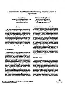
Fig. 2.
Recovery of the corrupted motion vectors.
since the rearranged bit stream is composed of the fixed-length slots of the MB layer, the GBSC’s are introduced to every th ), thus each GOB has the same slots ( should satisfy length, i.e., we use the same number of the GBSC’s in order to obtain identical bit rate of the conventional H.263. So, the sync positions in each bit stream layer can be derived easily from the total bits, consumed by the frame, and the CBP information as described in steps 1 and 2 of the encoding procedure. Thus, the proposed algorithm requires no redundant information, such as the average macroblock size or the average block size in each macroblock. In other words, the given bit rate is maintained, while providing much more robustness to the transmission errors. It is worth to note that the proposed HST requires additional 1-frame decoding delay, since the VLB’s can be placed at any locations in a frame. One may reduce this additional delay to 1-GOB, however, by applying the proposed HST to the GOB level, each of which is differentiated by GBSC’s. In this case, loss of one GBSC may result in loss of the whole GOBs before and after the corrupted GBSC. Fig. 1 shows an example for bit rearrangement in the MB and , and ) are conthe block layers, where three MB’s ( sidered and the MB header information (the CBP information
IEEE TRANSACTIONS ON CIRCUITS AND SYSTEMS FOR VIDEO TECHNOLOGY, VOL. 10, NO. 3, APRIL 2000
Fig. 3.
435
Macroblock structure of the base and the enhancement layer in the data partitioning.
and the motion vectors) is assumed to be included in each mac, roblock, ignoring the EREC on lower levels. Note that has three blocks with 9 bits, three blocks with 4 bits, and and two blocks with 5 bits, respectively. Therefore, we can get , and . Firstly, the coded blocks in each MB is rearranged as illustrated in the macroblock layer , whose in Fig. 1. As shown in Fig. 1, in the block layer of , each block is synchronized by placing size is longer than and filling the the first bit of th block at the position free space with one of the remaining bits, and then the others are buffered. Then, as shown in steps 2 and 3 of the macroblock are spread to other MB layer in Fig. 1, the buffered bits of slots, which are not fully occupied. Note that the decoder can be synchronized at the start of each MB by the bit rearrangement given in Fig. 1, even if the bit stream is corrupted by errors. Moreover, the header information of each MB, which includes the CBP information required for determining the block size, can be effectively protected against errors occurred at other MB’s. In similar way, the start points of VLB’s, such as MB, block and VLC, are also known to the decoder by the proposed HST. Hence, we can achieve fast synchronization by the proposed technique, while confining effectively the range of the error propagation. By rearranging the VLB’s to the fixed-length slots, the VLB’s, whose length is longer than the average size are spread to other slots and rearranged in the backward direction from the tail of each slot. Thus, the VLB’s are apt to be corrupted by the errors with high probability. In most cases, however, since only the high-frequency DCT coefficients are included in the dependent set,3 the degradation in the video quality would be unnoticeable. B. Recovery of the Erroneous Motion Vectors The conventional H.263 encodes the motion vectors, employing the differential pulse code modulation (DPCM). Thus, 3The dependent set: by rearranging the VLB’s to the fixed-length slots, the VLB’s, whose length is longer than the average slot size, are dispersed to other slots. In this case, we define the set of the slots associated with the dispersed bits as the dependent set.
even an error in one motion vector could damage the subsequent motion vectors significantly. But, since the differences in the motion vectors and DCT coefficients of the following MBs are successfully decoded in our approach, the corrupted motion vectors can be recovered, by extending the boundary matching algorithm [8]. As shown in Fig. 2, if the motion is corrupted, then it can vector of the th macroblock be recovered, by selecting possible motion vector minimizing , each of which is the sum the sum of of differences between the boundary pixel values of the th and that of its neighborhood, given by decoded macroblock (1) (2) (3) (4) (5) is the set of possible motion vectors, or , which is of half-pixel accuracy, and is the set of MB’s affected by the erroneous motion vector, respectively. If the th motion vector is erroneous, then the possible motion vector and the differential motion vector yield the , given by . For the given motion vector , the distortion in the boundary area is increased, due to the accumulation of the erroneous motion vectors. Therefore, the corrupted motion vectors can be recovered with more accuracy as the larger is available, even if perfect recovery cannot be guaranteed, where
III. DATA PARTITIONING TECHNIQUE In the data partitioning, the encoded video data is divided into the base and enhancement layers by the priority break
436
IEEE TRANSACTIONS ON CIRCUITS AND SYSTEMS FOR VIDEO TECHNOLOGY, VOL. 10, NO. 3, APRIL 2000
(a)
(b) Fig. 4.
The PSNR performance at various BER’s for average burst length 1.0 ms. (a) “Foreman” sequence. (b) “Carphone” sequence.
point (PBP) [5]. The relatively important information (the macroblock header, the motion vectors, and the low-frequency DCT coefficients) is transmitted in the base layer and the remnant (the high-frequency DCT coefficients) in the enhancement layer. As shown in Fig. 3, the encoded data in each coded block of a macroblock is separated into two layers, and then the coded block information (MCBPC and CBPY) is regenerated in each layer. Thus, each layer has the same structure as in the H.263, implying that the proposed error-localization algorithm can be applied to both the layers without modification, and the error-resilience is guaranteed for given transmission bandwidth, yielding no degradation in the video quality. In most cases, it is generally assumed that no error occurs in the base layer [6], or the base layer is loss-free, using sufficient redundancy in FEC codes [7], but it is not always true in the wireless network, in which each layer is subject to the equi-probable losses, implying that the performance mostly depends on the effects of the bit errors in the base layer. Thus, the base layer, as well as the enhancement layer, should be tightly
protected against the channel errors at realistic bit rate, which can be achieved by the proposed synchronization technique. That is, based on the H.263 compatible bit stream structure, in order to provide the UEP and alleviate the degradation in the video quality, the error-localization technique is employed hierarchically in each layer. Since both the layers are composed of the same bit stream structure, the same bit rearrangement procedure is applicable. But, because of the following reasons, in spite of equivalent synchronization in both the layers, the base layer is more effectively protected against the errors, and the UEP-like characteristics are attainable, alleviating the degradation in subjective video quality. The base layer can be encoded at the constant bit rate (CBR), by controlling the PBP. In other words, the MB and the coded block size can be made nearly constant in each frame, making the size of the dependent set decreased. Notice that, in the EREC structure, as the variation in the size of VLB’s increases, the errors are more severely propagated and vice versa [3]. Therefore, the error propagation can be almost prevented in
IEEE TRANSACTIONS ON CIRCUITS AND SYSTEMS FOR VIDEO TECHNOLOGY, VOL. 10, NO. 3, APRIL 2000
(a) Fig. 5. “Foreman” 4th frame with
(b)
BER = 10
(b)
BER = 10
(c)
for average burst length 1.0 ms. (a) Original image. (b) H.263, 23.40 dB. (c) DP
(a) Fig. 6. “Carphone” 58th frame with
437
+ HST + MVR, 29.44 dB.
(c)
for average burst length 1.0 ms. (a) Original image. (b) H.263, 27.69 dB. (c) DP
the base layer, and the UEP can be achieved, without the loss of coding efficiency.
IV. SIMULATION RESULTS The proposed algorithm is evaluated on the real “Foreman” and “Carphone” sequences, which are in the standard QCIF format with the frame rate of 8.33 frames/s. In the simulations, the video sequences are encoded with a quantizer parameter of 10, which is half of the quantizer step size. Then, the base layer is transmitted at CBR by controlling the PBP, and the enhancement layer at the variable bit rate (VBR). The simulation is performed at various BER’s, and average burst length varies from 0.1 to 10 ms. The overall bit rate for the “Foreman” sequence is 60.68 kb/s (29.66 kb/s for the base layer and 31.02 kb/s for the enhancement layer), and that for the “Carphone” sequence is 42.49 kb/s (20.31 kb/s for the base layer and 22.18 kb/s for the enhancement layer). In comparison, we consider the conventional H.263 and the H.263 with the conventional EREC (63 kb/s for the “Foreman” sequence and 41.58 kb/s for the “Carphone” sequence). Here, in H.263 with the conventional EREC, the EREC is applied in the macroblock layer only and GBSC’s are introduced at regular intervals as in the proposed algorithm. In the conventional H.263, we employ the simplest EC, in which the corrupted blocks are replaced by the blocks at the same location in the previous frame. Under these conditions, we examine the performance of the proposed HST, the EREC, H.263, and the DP technique combined with the proposed HST. In each case, we also consider the performance for with or without the proposed motion vector recovery (MVR) algorithm.
+ HST + MVR, 30.68 dB
Fig. 4 shows the PSNR performance at various bit error rates for average burst length 1.0 ms. The results show that the proposed HST and the DP combined with the proposed HST provide much better performance objectively than the conventional methods, and moreover, the performance improvement is more pronounced at higher bit error rates. As shown in Fig. 4, the EC by the MVR yields the improved performance, since it can effectively reduce the effect, due to the errors, specifically in the interpicture prediction. Again, the proposed HST combined with the DP yields substantial improvement over the EREC. The performance improvement by the DP is dominant at high bit error rates, while the HST is effective at relatively low bit error rates. For examples, the proposed technique DP HST MVR yields 0.5 dB and 1 dB improvements over the HST MVR on the and the EREC MVR, respectively, at BER “Foreman” sequence. However, the performance improvement is not significant on the “Carphone” sequence, in which relatively slow motions are present. For longer bursts (i.e., longer than the average MB size), it can be easily expected that the gain from HST MVR to EREC MVR decreases and the performance improvement by the MVR becomes dominant. Fig. 5 shows the fourth frame of the reconstructed “Foreman” for average burst length 1.0 ms. sequence with Since there exist fast motions in “Foreman” sequence, the conventional method yields severe degradation in quality, and the simplest EC makes some criss-cross in the erroneous MB’s. On the other hand, the proposed algorithm is shown to make the damaged area to be subjectively less visible. Fig. 6 shows the for 58th frame of the “Carphone” sequence with average burst length 1.0 ms. Since there exist relatively slow motions in “Carphone” sequence, the damaged area, due to the
438
IEEE TRANSACTIONS ON CIRCUITS AND SYSTEMS FOR VIDEO TECHNOLOGY, VOL. 10, NO. 3, APRIL 2000
channel errors, is not distinctly visible. That is, the degradation in the subjective quality is more distinct as there exist relatively faster motions. As mentioned previously, notice that only the high-frequency DCT coefficients are affected by the errors. V. CONCLUSION This letter presented an error-resilient transmission technique for the H.263 compatible video data stream over error-prone channels. The proposed algorithm provides more efficient protection to the relatively important information. Moreover, the erroneous motion vectors can be recovered effectively. The experimental results demonstrated that the proposed algorithm yields an adequate video quality both subjectively and objectively, in spite of transmission errors, and prevents effectively the error propagation both in the spatial and the temporal domain.
REFERENCES [1] S. B. Wicker, Error Control Systems for Digital Communication and Storage. Englewood Cliffs, NJ: Prentice-Hall, 1995. [2] Q.-F. Zhu, Y. Wang, and L. Shaw, “Coding and cell-loss recovery in DCT-based packet video,” IEEE Trans. Circuits Syst. Video Technol., vol. 3, pp. 248–258, June 1993. [3] D. W. Redmill and N. G. Kingsbury, “The EREC: An error-resilient technique for coding variable-length blocks of data,” IEEE Trans. Image Process., vol. 5, pp. 565–574, Apr. 1996. [4] Video Coding for Low Bitrate Communication, ITU-T DRAFT H.263, May 1996. [5] Video Recommendation ITU-T H.262, OS/IEC 13 818-2, Jan. 20, 1995. [6] R. Aravind, M. R. Civanlar, and A. R. Reibman, “Packet loss resilience of MPEG-2 scalable video coding algorithms,” IEEE Trans. Circuits Syst. Video Technol., vol. 6, pp. 426–435, Oct. 1996. [7] E. Ayanoglu, P. Pancha, A. Reibman, and S. Talwar, “Forward error control for MPEG-2 video transport in a wireless ATM LAN,” in Proc. ICIP 1996, Sept. 1996, pp. 833–836. [8] M.-J. Chen, L.-G. Chen, and R.-M. Weng, “Error concealment of lost motion vectors with overlapped motion compensation,” IEEE Trans. Circuits Syst. Video Technol., vol. 7, pp. 560–563, June 1997.