an immediate solution due to the case that lines up. .... Using them, expert system was built up and is .... to analysis, since upper flange, bath-tub fixer and.
International Journal of the Korean Society of Precision Engineering Vol. 1, No. 2, December 2000.
A Knowledge-Based System for Assembly Sequence Planning Hong-Seok Park* * School of Mechanical and Automotive Engineering, University of Ulsan, Ulsan, South Korea
ABSTRACT To save time and cost in assembly process and to improve the quality of products, it is very important to choose an optimal assembly sequence. In this paper, we propose a methodology that generates an optimal assembly sequence by using various methods and the knowledge of experts. To illustrate the effectiveness of the proposed methodology, a knowledge-based system is developed. The built system is applied to the case of UBR(Unit Bath Room). The applying result showed the applicability of the developed system. Keywords: Disassembly rules, subassembly generation, assembly parameters, alternative sequence evaluation subassemblies on the simple connect relationship information in some other way of the existing studies, and also prevent impractical and unnecessary processes by using disassembly methods with CAD model. To conduct this procedure smoothly, disassembly rules are developed. The information for the next evaluation phase such as assembly method, setup change and accessibility through this process are grasped. Evaluation using the above information can improve the accuracy of solution. In order to get a practical solution, we induced the factors that are used in measurement of economy and difficulty of assembly, by analyzing many assembly tasks and gathering experts knowledge and much experience.
1. Introduction The existing studies for assembly planning have progressed by the ways that generate assembly sequences on the basis of subassemblies inputted manually and then select final solution through evaluation. (Gu & Yan, 1995; Jones & Wilson, 1996; Qian & Pagello, 1994; Wolter, 1991) These ways were carried out by the inference of assembly-restricted condition via a number of question and answer. Due to these reasons, the detailed description of the geometrical shapes and connect relationships of parts was required. Nevertheless, the existing studies have defects that the generated assembly sequences even include impractical one and exponentially increase in proposition to the number of parts. According to the kind of product and assembly circumstances, evaluation of assembly sequences requires various evaluation factors. But, because the existing studies havent sufficiently considered geometrical relationships and the degree of assembly difficulty, the evaluation are not only unsatisfactory but also applied only simple assembly problems (Wolter, 1991). In order to overcome the above problems, the developed system automatically generates
2. Generation of Assembly Sequence 2.1 System Architecture Generation system of assembly sequence is consisted of several subsystems like subassembly generation tool, disassembly sequence generation tool, all the feasible assembly sequence generation tool, expert system for the optimal assembly sequence and database system for managing and storing all data to utilize each tool. These data contain the assembly information acquired from disassembly process and drawings of a product.
35
Hong-Seok Park : International Journal of the KSPE, Vol. 1, No. 2
subassembly is developed (Figure 2). Input formation is generated by describing all parts that the part has a contact relationship on the basis of each part. By this way, to describe all contact relationship for entire parts is called a contact relationship matrix. The part that is only connected by one part is regarded as single node. To form the closed polygon, it is removed from contact relationship matrix first. It must be recorded wh at part was connected with it when removed. After that, we check if the row which is consisted of the identical parts exist within contact relationship matrix. If exist, we store it as intermediate solution. And then we remove it from the connected parts within contact relationship matrix. Next, we examine whether a row is partially contained in other row. In the case of not existing the row consisted of the completely same parts in the previous step, we investigate a partial set relationship for the entire row. On the other side, in the case that exists the same row, we investigate whether the comparing row is contained in the connected parts of the compared row within contact relationship matrix which is removed the identical parts. For each case, as shown in the middle decision statement in the Figure 2, the comparing row (A) in the former case
CAD System
Optimal Assembly Sequence Generation Tool
• Solid Model Data • Product Analysis - Contact Relationship - Part Information (weight, dimension…)
Subassembly Generation Tool 5
2
4 3
7 1 Op 8 6 Ass timal Geometric and Analysis em bly Information of Product nship B 29 D A …. Se q io t uen •Liaison Graph Fea ela R c e s t Ass ible •Subgroup Generation Database Contacrt em bly Pa bly •Subassembly Generation Seq •Assembly Knowledge of sem n uen •Selection of the Optimal bas tio ce Su orm a Assembly Sequence Inf ce Su en Disassembly Sequence b le q u Inf assem si b S e orm bly Generation Tool Dis Assembly Sequence l Fea bly ce atio a s n s Te l m e n chn embly Generation Tool A Asse y equ l olo b gy Sequ m ly S In f e sse b A B 29 D …. or m nce, ba sem atio B 29 D A …. Su isas n D •Disassembly Knowledge •Information on Assembly Process •Interference check •Generation of all •Disassembly Sequence of Subassembly Feasible Assembly Sequence A
B
29
D ….
...
...
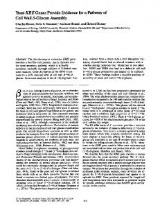
System configuration and data flow among subsystems are shown in Figure 1. First of all, through analysis of a product on CAD system, Fig. 1 System Architecture information such as geometric connect relationship, weight, dimension and material are grasped. The acquired information is stored in database system. First, subassembly module generates a product's subassembly on the basis of connect relationship information of part. Next, disassembly operation is performed by simulation tool on the solid model of parts as the unit of the previously generated subassembly. In this process, the disassembly rules developed are used. The acquired disassembly sequence and technical information through disassembly process are stored within database system by planer. The third subsystem generates all feasible assembly sequences by combining disassembly sequence of each subassembly generated from disassembly system in reverse order. Finally, such generated assembly sequences are evaluated by using evaluation criteria. The optimal solution selected by these processes is the final result of the developed system.
Input of part contact relationship Remove single node from connected parts of the matrix
Exist the composition of identical parts within the matrix? YES
NO
Store it as the Intermediate Solution Remove the stored parts from connected parts of the matrix
Partial set relationship {A}⊂{B}
Partial set relationship {A}⊂{connected parts of B}
YES NO
Store A as intermediate Solution
YES Store B as intermediate Solution
NO
Remove the stored parts from connected parts of the matrix Store as an intermediate solution by combining two rows with more than two identical parts Remove the stored parts from connected parts of the matrix Store as an intermediate solution by combining two rows with the same part
2.2 Subassembly Generation Tool
Combine two intermediate solutions with more than two identical parts among the determined intermediate solutions
In this paper the minimum assembly planning unit that generates assembly sequences is formed with the unit of subassembly. Subassembly is composed of a subgroup or a combination of various subgroup. Subgroup is defined as a set of parts divided on the
Add single node into the intermediate solution Subgroup determination Basepart selection Subassembly generation
Fig. 2 Flowchart for the generation of sub-assembly and the compared row(B) in the latter are stored as
Liaison Graph(Qian & Pagello, 1994). Under this concept, algorithm for generation of
36
Hong-Seok Park : International Journal of the KSPE, Vol. 1, No. 2
an intermediate solution. As the previous steps did, after storing, it is removed from the connected parts of contact relationship matrix. In next step, in the case of rows having more than two identical parts by comparing each row, we store as an immediate solution by connecting two rows. To have more than two identical parts means that all parts of two rows are contained in the closed polygon when drawing it. That is, it means that two rows cannot be separated. They are stored as an immediate solution, and then are removed from the connected parts of contact relationship matrix. Also, by combining two rows having an identical part, an immediate solution is generated, This case is not composed of the closed polygon, but is stored as an immediate solution due to the case that lines up. So, process that generates the immediate solutions from contact relationship matrix is completed. Finally, by comparing the immediate solutions generated above, two immediate solutions that have more than two identical parts are combined as an immediate solution because they consist of the closed polygon that lies adjacent to each other. And then, if the single node removed early is added at the parts related to the above generated solution, subgroup is generated. The existing studies that depend on the simple Liaison Graph generate the assembly sequence by unit of subgroup. In this case, if the several subgroups on the basis of a common part are generated, it can be impossible to assemble due to the geometric interference according to assembly sequence among subgroups. Therefore, this method doesnt always generate the correct result. Specially in the case of machinery assembly, the situation that various subgroups are formed around a centered common part like assembly around axis often happen. We can know from the analysis result of Liason Graph for that this problem happens when common part has the property of basepart various products. Thus, in order to prevent the interference problem in advance, it is appropriate that a subassembly is formed by the subgroups connected around centered basepart on the basis of the generated Liason Graph. The selection of basepart is achieved by calculating the weights which are suitable for the given assembly task in considering
weight, the number of the connected parts, and size acquired for, the input of part information.
2.3 Disassembly Sequence Generation Tool It is very difficult to develop the strategy and rule that can generally apply to the generation of assembly sequence in synthetic consideration of the variety of assembly tasks, methods, and product structures. Some systems using simple rules are introduced, but it is only useful under a limited condition. In this research a product is divided as subassemblies by the tool developed in the previous section and the disassembly operation is performed by disassembly rules on UG simulation tool with the CAD solid model of each subassembly. Disassembly rules are derived from the much experience of field experts, assembly theory and many assembly tasks. A part of disassembly rules is introduced as follows: Disassemble the part that is easy to guarantee operation space earlier, avoid gravity orientation in disassembly direction, disassemble the part that is superior to flexibility earlier, disassemble the part that has many simultaneous contacts in disassembly as late as possible, etc. A planer determines the disassembly sequence according to the given disassembly rules, and stores the assembly information such as assembly direction, setup change and the shape of assembly location for accessibility into the database of the system. The derived information can be used as evaluation criteria to select the optimal assembly sequence in expert system. We can select the better solution by estimating more various parameters through this information.
2.4 Generation Of Feasible Assembly Sequences All feasible assembly sequences should be generated by combining all assembly sequences of each subassembly. Parts that have priority rather than the sequence of common part in a subassembly always have priority rather than the assembly sequence of common part. Also, parts that are later assembled rather than common part are always assembled later rather than the assembly sequence of common part even in the
37
Hong-Seok Park : International Journal of the KSPE, Vol. 1, No. 2
case of generation of the entire assembly sequence. Like the above explanation, the assembly sequence of each subassembly can be combined with one.
disassembly by analyzing the access patterns in disassembly operation. For example, if the assembly is accomplished in a pocket of part, the degree of freedom for the assembly is equal to 1 because of the accessibility of one direction only. And, in the case that is assembled in a plain, the degree of freedom for assembly is equal to 5 since assembly make possible for all directions exclusive of Z direction. To reduce the non-processing time of assembly operation, it is appropriate that the process using the
2.5 Parameters For Evaluation Of Assembly Sequence To capture parameters that have an influence on the determination of assembly sequence, the various kinds of assembly sequences are systematically analyzed in the technical and economical aspects. Several experiments show that assembly sequence is largely influenced by the joined shape and structure of parts(Ben-Arieh,1994; Tönshoff et al, 1992). In relation to that, parameters for the determination rules of assembly sequence are derived. Each parameter is weighted by the degree of importance for the determination of assembly sequence by considering cost, time, and difficulty on assembly process(Figure 3). This is performed by the synthetic assessment on
Assembly Freedom
the basis of experiments results and expert knowledge. Errors on arrangement and position are strictly controlled in the automated assembly, but also have an important effect upon the easiness and time of assembly operation in the manual assembly. Assembly operation should be performed under the minimum setup change because these errors are incurred by the setup change. Specially, the setup change of the heavy and bulky products such as industry machines bring sometimes about the huge additional expenses and time loss. These changes can be recognized by the required jig and fixture, setup location, etc. acquired in disassembly operation. According to experiment results, the adjacent shapes to assemble play an important role in assembly process. Assembly operation in the unrestricted accessibility is performed much easier than the assembly operation in the limited space. Therefore, the assembly operation must be performed in the easily accessible direction at the location of assembly. For this, we classified the degree of freedom for assembly into 5 types from 1 to 5 by analyzing the jointing spot. The direction for assembly is defined into 6 axes (±X, ±Y, ±Z), and on the basis of this, the accessibility on assembly operation of each part is evaluated according to the degree of freedom for
Fig. 3 Parameters and weight values for the selection of assembly sequence
identical tools and same direction in a setup is composed of as a group. The productivity of assembly is improved by changing tools after performing assembly operations of each different direction with the identical tools. Therefore, the assembly sequence that has the small number of tool
38
Hong-Seok Park : International Journal of the KSPE, Vol. 1, No. 2
change was selected preferentially. Joint method is connection by shape of parts and kind of joining[5,6]. In connection with this, the correlation between joint method and assembly sequence is investigated. Technically, assembly sequence is accomplished according to the degree of difficulty for assembly which was evaluated by the force required to joining and the complication of operation required in the assembly process. Generally, assembly sequence is from joint method with the low degree of difficulty to joint method with the high degree of difficulty. In economic aspect, the indivisible joint method must be performed earlier than the divisible one. It can reduce the loss of materials to that extent because a minimum assembly was performed through the wrong assembly can be taken. But, in the case of welding, assembly is performed later for continuous assembly progress because of transformation by heat. According to the experiment result, the more the number of parts increase, the harder assembly is performed. Thus, the later the hard assembly operation is performed, the worse the assembly sequence grows. For assembly stability, assembly must be progressed under the symmetrical structure as much as possible. Also, the sensitive or expensive parts should be assembled later in order to prevent from the damage of them. Thus, we caused them to be selected the late assembly sequence as far as possible. According to this study, basepart should be assembled as early as possible because it has an ability to accommodate other parts. So, in the case that basepart is assembled first, the results of
parts taken from the drawing, assembly information acquired through disassembly operation such as direction change, tools used and the degree of safety and subassembly information are stored in database. Expert system is run on the basis of the built database. It is impossible that all parameters affected to assembly are quantitatively evaluated and are represented. A property of working method in field and assembly system cannot help evaluating qualitatively. Therefore, through communication with the developed system, a planer and an expert made the final decision in consideration of the qualitative amount.
3. Case Study The developed system using the above proposed methodology was applied to a UBR (Unit Bath Room) for a prefabricated building in order to show the steps choosing optimal solution. Through these steps, we verified various methodologies used in system, and investigated the effects of the rules and the evaluated parameters proposed in this paper. UBR is made up of the first parts that form basic structure and the second parts that is the inside function part. This case made assembly of the second parts an object of study. The second parts are composed of 17 parts. The related parts are provided in the form of CAD Model from a company. First of all, the connecting relationship of each part and the product information are stored at database. This process is performed by analyzing CAD Model and design information of product. On the basis of the described input information, sub-assembly is generated using the sub-assembly generation tool. In the case of UBR, because of spatial constraint the weight and size of part should be given much more weight than the number of the connected parts at the determination of the basepart. With this criteria, a bathtub is selected as basepart.
assembly are evaluated as good. Since each parameter introduced above has its own property for determination of assembly sequence, it is embodied in the form of the rules of IF-THEN. Using them, expert system was built up and is applied to decide the difficulty of the entire assembly. Each parameter is evaluated individually and is finally quantified by multiplying weight on the property of assembly.
The following Figure 4
2.6 Algorithm For Selection Of Assembly Sequence Product information like weight and volume of
39
Hong-Seok Park : International Journal of the KSPE, Vol. 1, No. 2
The final step is to select optimal assembly sequence using the knowledge for various judgements on the basis of input information such as all assembly sequences generated. The following Figure 6 shows the final result estimating two feasible assembly sequences. As a result, we can know that assembly sequence 1 gets higher score than assembly sequence 2. In the aspect of the assembly direction change, the precedence of the joint method, the assembly safety and the location of basepart the alternative sequences are different. A few kinds of tool is used and there is no difference in tool change. Because the UBR parts are assembled in enough spatial allowance, accessibility of jointing
Fig. 4 Result of sub-assembly generation
Fig. 5 Disassembly process of sub-assembly
show the result of sub-assembly displayed in the form of the given part numbers using the sub-assembly tool. The next procedure is to carry out disassembly task per the unit of the generated sub-assembly. This task is performed through the call of UG assembly module in developed system and the results are stored at database. At this procedure, various disassembly rules proposed in section 2.3 are used. And, through this process, information such as assembly direction, the degree of freedom for assembly, and setup change, is acquired, and is also stored at database, and is used in the evaluation step of the final assembly sequence. The following Figure 5 shows disassembly process of sub-assembly. The next step is to generate all feasible assembly sequences by combining assembly sequence of sub-assembly. This process is accomplished by a perception of the common part in sub-assemblies.
(a) Feasible sequence 1
(b) Feasible sequence 2 Fig. 6 Results of assembly sequence evaluation
40
Hong-Seok Park : International Journal of the KSPE, Vol. 1, No. 2
related to this field. And after small parts are previously assembled with the parent part involved with them, we have the next assembly performed. This gives a convenience in the actual assembly operation. Also, because of reduction in the number of changes of tools used or assembly direction, we can expect the reduction of time.
4. Conclusion (a) Conventional sequence In this paper the influential factors required to generate the assembly sequence and the parameters for evaluation of assembly are derived through analysis of various assembly tasks. On the basis of this information, a knowledge-based system is developed for selection of the optimal assembly sequence among various solutions. To verify the performance of the developed system, the case of UBR (Unit Bath Room) is applied. The result is proved by field experts in view of the good solution for assembly planning of real world. The advantages of our system are as follows. First, an abundant knowledge and experience of a field expert was employed. Second, the subassembly is automatically generated from connecting information of parts. Third, information taken from disassembly operation such as orientation change and setup change that is difficult to consider was used at
(b) New sequence Fig. 7 Comparison of the conventional sequence with the new sequence assembled in enough spatial allowance, accessibility of jointing spot is not restricted in case of the degree of assembly freedom. With these step, the assembly sequence generated from the developed system and the conventional assembly sequence from experience are compared (Figure 7). In the above assembly sequence diagram, hose in conventional sequence is considered as one, but the new assembly sequence is generated by dividing it into two hoses A. B because assembly task is performed at the different time and place. According to analysis, since upper flange, bath-tub fixer and toilet bowl base regarded as single node have no influence on change of assembly sequence, we proposed that they should be assembled as the previous assembly at the time of assembly for the first parts. Generally, we can know that two assembly sequences have a pretty similar aspect. Through this, we can verify that proposed system is developed utilizing the enough knowledge of the existing experts
the evaluation of assembly sequence. Further study areas are the improvement of the degree of automation for the generation of automated assembly sequence with abundant disassembly rules and the direct application of feature from CAD data, and the method of development and quantification of various parameters for evaluation of the optimal assembly sequence.
Acknowledgement This work was supported (in part) by the Korea Science and Engineering Foundation(KOSEF) through the Research Center for Machine Parts and Materials Processing(ReMM) at University or ulsan.
41
Hong-Seok Park : International Journal of the KSPE, Vol. 1, No. 2
References 1. Ben-Arieh, D. “A methodology for analysis of assembly operations difficulty, Int. journal of Production Research,” Vol. 32, No. 8, pp. 2.
1879-1895, 1994. Gu,P. & Yan,X. “CAD-directed automatic assembly sequence planning, Int. Journal of Production Research,” Vol. 33, No. 11, pp.
3069-3100, 1995. 3. Jones, R. E. & Wilson, R. H., A Survey of Constraints in Automated Assembly Planning, Proc. IEEE International Conference on Robotics and Automation, pp. 1525-1532, 1996. 4. Qian,W.-H. & Pagello,E., On the Scenario and Heuristics of Disassembly, IEEE, pp. 1050-1079, 1994. 5. Tönshoff, H.K.; Menzel, E. & Park, H.S. “A Knowledge-Based System for Automated Assembly Planning,” Annals of the CIRP Vol. 41, pp. 19-24, 1992. 6. Wolter, J.D., On the Automatic Generation of Assembly Plans, in Computer-Aided Mechanical Assembly Planning, edited by L. S. Homem de Mello and S. Lee, Boston: Kluwer Academic Pub, pp. 263-288, 1991.
42