A method for modular design of structural products such as automotive bodies ...... sored Course in the University of Michigan, ME599 Coursepack, University of.
O. L. Cetin* Graduate Student
K. Saitou Associate Professor Dept. of Mechanical Engineering, University of Michigan, Ann Arbor, MI 48109
1
Decomposition-Based Assembly Synthesis for Structural Modularity A method for modular design of structural products such as automotive bodies is presented where two structural products are simultaneously decomposed to components considering the structural performances of each structure and the component sharing between two structures. The problem is posed as an optimization to minimize the reduction of structural strength due to the introduction of spot-weld joints and the number of redundant joints, while maximizing the manufacturability of the component and component sharing between two structures. As an extension to our previous work, this paper focuses on the simultaneous decomposition of two 3D beam-based structures. The major extensions include 1) a new, realistic definition of feasible joining angles based on the local geometry of joining components, 2) a component manufacturability evaluation that eliminates the need of specifying the number of components prior to decomposition and 3) a multi-objective optimization formulation that allows an effective exploration of tradeoffs among different criteria. A case study on the simplified, 3D beam models of automotive bodies is presented to demonstrate the developed method. 关DOI: 10.1115/1.1666890兴
Introduction
Modularity is a tested and proven strategy in product design. One short description would be having products with identical internal interfaces between components. The scope of the word interface includes the connection between components in functional, technology and physical domains. The interfaces between components are seen by many as the core issue of modularity and they must be standardized to allow the ability of the full exchange of components 关1兴. Design for modularity is now in widespread use globally. Carmakers prefer designing many features of a family of cars at the same time, instead of one model at a time. Standardizing components and letting several variant products share these components would save tooling costs and many related expenses 关2– 4兴. Developing a complex product involves many activities and people over a long period of time. Making use of modularity leads to the clustering of activities involved in the design process, so that the potential group of activities might be scheduled simultaneously, which enables simplification of project scheduling and management 关1兴. As the identification of modules tremendously affects the entire product development process, the strategy is usually applicable in the early phases of the design process. Many companies are also actively pursuing to replace the traditional design process, where the translation of conceptual designs into the final products to be manufactured has been accomplished by iterations between design and manufacturing engineers. In particular, design for manufacturability 共DFM兲 and design for assembly 共DFA兲 methodologies are utilized to implement the early product design measures that can prevent manufacturing and assembly problems and significantly simplify the production process. Most existing approaches generate redesign suggestions as changes to individual feature parameters, but because of the interactions among various portions of the design, it is often desirable to propose a judiciously chosen combination of modifications 关5,6兴. *Current Research Associate Engineering Design Centre, Cambridge University, UK. Contributed by the Design Automation Committee for publication in the JOURNAL OF MECHANICAL DESIGN. Manuscript received July 2002; revised July 2003. Associate Editor: G. Fadel.
234 Õ Vol. 126, MARCH 2004
In this paper we introduce a method to combine the DFA and DFM concepts with the design for modularity process. The objective is to identify the modules in the early development stage of structural products and optimally design the interfaces. Decomposition based assembly synthesis 关7兴 is applied to search for the basic building blocks of a product and determine the locations of joints that will result in the minimum decrease in structural strength. As an extension to our previous work 关8,9兴, this paper focuses on the simultaneous decomposition two 3D beam-based structures. The major extensions include 1兲 a new, realistic definition of feasible joining angles based on the local geometry of joining components, 2兲 a component manufacturability evaluation that eliminates the need of specifying the number of components prior to decomposition, and 3兲 a multi-objective optimization formulation that allows an effective exploration of trade-offs among different criteria by generating a set of Pareto optimal solutions. A case study on the simplified, 3D beam models of automotive bodies is presented to demonstrate the developed method.
2
Previous Work
In the design of a family of products, a shared subsystem with common components and interfaces, based on which product variants can be derived, is often referred to as a product platform, On the other hand, term ‘‘modular components’’ or simply ‘‘modules’’ are also used as common 共often small, individual兲 components sharable across the multiple product types in the context of product family design. While a product platform implies a large subsystem in a product consisting of multiple components 共eg. bolts and nuts are not product platforms but they are modular components兲, it is also termed as modules in the rest of the paper for the sake of consistency. Recently, there has been considerable increase in the research directed towards modular design. Rather than providing an exhaustive list of design for modularity, this section focuses on the previous work dealing with relatively complex applications involving mathematical optimizations. The reader should refer to 关8,9兴 for the previous work related to assembly synthesis and structural optimization. In the following, a classification similar to the one found in 关10兴 is adopted:
Copyright © 2004 by ASME
Transactions of the ASME
• Class I: Given product variants and modules to share, find the module attributes 共parameters associated with modules such as size and weight兲 that optimize the performances of each product variant. • Class II: Given product variants, simultaneously find the modules to share and their attributes that optimize the performances of each product variant. Note Class II problems, addressed in this paper, involve the decisions on which modules to share, and hence imposes considerably more challenges than Class I problems. Zugasti et al. 关11兴 started with several predefined module alternatives and design variants. In this Class I formulation the optimal product family can then be identified based on decision analysis and real options; modeling the risks and delayed decision benefits present during product development. Another example of Class I formulation is reported by Nelson et al. 关12兴, where a multicriteria optimization problem is formulated whose solution quantifies the performance degradation of product variants by component sharing. For each selection of modules to share, the performance trade-offs between two product variants are represented as a Pareto curve. Several such Pareto curves are shown to illustrate the effect of different module selections on the performances of the two product variants. While the optimal module design should be on one of these Pareto curves, exactly which one is the best is a question of performance as well as of other business issues. Simpson et al. 关13兴 focused on a slightly different Class I application, introducing the Product Platform Concept Exploration Method to design scalable modules and the resulting product variants. The goal is to design a product that can be vertically leveraged for different market niches. Some parameter values in the modules are shared across given product variants, while other parameters can take different values within each product variant. A group of individually optimized products are compared with the product variants with shared modules, and it is reported that component sharing is achieved without a considerable loss in performance. Due to its complexity, there are a handful of past attempts for Class II problems. Fujita and Yoshida 关10兴 presented an optimization method combining genetic, branch-and-bound and nonlinear programming algorithms. In their multi-level technique, they first optimize the module selection and similarity among different products using genetic algorithm, then optimize the directions of similarity on scale-based variety using branch-and-bound, and finally optimize the module attributes as nonlinear programming. Simpson and D’Souza’s 关14兴 presented a mixed-integer programming formulation of the single-stage design for modularity problem where binary variables represents the selection of modules within a product family and continuous variables specify parameter values associated with each module. Fellini et al. 关15兴 discussed a similar approach where the binary variables for module selection is relaxed to a continuously differentiable function that takes values in 关0,1兴, to allow the use of gradient-based optimization algorithms. Extending the work of Simpson et al. 关13兴, Messac et al. 关16兴 introduced a product family penalty function to simultaneously maximize the performances of each design variant and minimize the variations in parameter values associated with chosen modules. Based on the decomposition-based assembly synthesis method 关7兴, We presented a method to solve a Class II problem for structural products in 2D continuum models 关8兴 and 2D beam models 关9兴.
3
Modular Structural Component Design
The modular structural component design problem addressed in this paper is posed as an optimization of the locations of joints and joint types within two variants of a structural product. Considering automotive body applications, the locations and types of joints are selected to 1兲 minimize the reduction of structural strength due to the introduction of spot-weld joints in each structure, 2兲 minimize the number of redundant joint in each structure, 3兲 maximize the Journal of Mechanical Design
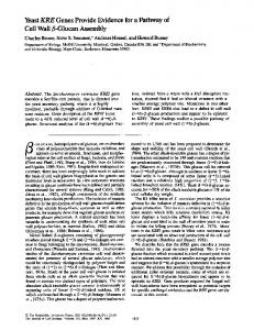
Fig. 1 Example of two product variants †9‡: „a… design domain and boundary conditions, and „b… two topologically optimal structures to be decomposed. Note that the product, variants do not have to be topologically optimal.
manufacturability of the components via stamping processes in each structure, and 4兲 maximize component sharing between two structures. The variant structures are assumed to bear some similarity but are distinct in the geometry and/or loading conditions. Figure 1共b兲 shows an example of two variant structures 关9兴, which are obtained with the beam-based topology optimization on the design domain and boundary conditions shown in Fig. 1共a兲. While the developed method is tailored for 3D beam-based structure models, we will use these simple 2D structures to illustrate each step in the method for the rest of this section. It should be noted, however, that the product variants do not have to be topologically optimal as seen in the case study in Sec. 4. Based on the decomposition-based assembly synthesis method 关7兴, in the modular structural design problem two beam-based structures are optimally decomposed into an assembly consisting of multiple members with simpler geometries. Given two design variants and the results of FEM analysis 共stress distributions within structures兲 for desired loading conditions, there are two main steps in the decomposition process: 1. Construction of the product topology graphs of each structure: The designer defines the basic ‘‘atomic’’ components 共minimum units subject to decomposition兲 on each structure, and a graph is constructed that represents the connectivity of these basic components within the structure, where each node indicates a basic component and each edge indicates potential joining points. If the basic components are simply defined as the beam segments in a structure 共as in the case of the following examples兲, the edges in the product topology graph represent the intersection points of these beam segments.12 For example, Fig. 2 illustrates the topology graphs of the two 2D structures in Fig. 1共b兲. 2. Decomposition of the product topology graphs: The product topology graphs are decomposed so as to maximize or minimize objective functions while satisfying constraints. In the multiobjective formulation presented below, there are four objective functions measuring the structural strength and number of joints in the assembled structures, the manufacturability of components in each structure, and the amount of component sharing between two structures. 3.1 Definition of the Design Variables. Let a product topology graph be G⫽(V,E) where V and E are the sets of nodes and edges, respectively. A decomposition of G into subgraphs can be represented by a 兩E兩-dimensional vector x⫽(x 1 ,x 2 , . . . ,x 兩 E 兩 ) of a binary variable x i indicating the presence of edge e i in the decomposition: 1 If a beam-based structure is seen as a graph, the product topology graph is the dual of the graph of the structure 关17兴.
MARCH 2004, Vol. 126 Õ 235
Fig. 4 A detailed illustration of type 1 joint in Fig. 3„a… †18‡. Beams A and B are also made of sheet metals joined by spot welds.
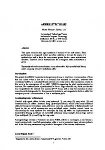
son, Type 4 共Fig. 3共c兲兲 and Type 5 共Fig. 3共d兲兲 are distinguished because the weld planes face the opposite directions. It should be noted that beams A and B in Fig. 3 are simplifications of two strips of bent sheet metals spot-welded to form a closed cross section, as illustrated in more detail in Fig. 4. One element of set J is 0, representing no spot weld at the corresponding joint, hence: Fig. 2 Product topology graphs of „a… the structure on the left, and „b… the structure on the right in Fig. 1„b…
x i⫽
再
1
if edge e i exists in the decomposition
0
otherwise
(1)
If x i ⫽0, edge e i is ‘‘cut’’ in the decomposition, and the two components corresponding to the two nodes incident on e i can be either joined or left as separated. If joined, the type of joints then must be specified. This can be represented as another 兩E兩dimensional vector y⫽(y 1 ,y 2 , . . . ,y 兩 E 兩 ) of a variable y i 苸J, where J is a set of feasible joint types. Assuming the structure is made of sheet metal with spot weld joints, the four typical types of joints shown in Fig. 3 are considered: • • • •
Type Type Type Type
1: 2: 3: 4:
butt joint of beam A onto B 共Fig. 3共a兲兲 butt joint of beam B onto A 共Fig. 3共b兲兲 lap joint of beam A onto B from top 共Fig. 3共c兲兲 lap joint of beam A onto B from bottom 共Fig. 3共d兲兲
The classification of these types is based on the orientation of weld planes that determine the normal and tangential force components the joints are subject to, which is the major governing factor of the joint strength as discussed in Sec. 3.3. For this rea-
Fig. 3 Four types of joints that connects two beams A and B. „a… butt joint of A onto B „type 1…, „b… butt joint of B onto A „type 2…, „c… lap joint of A onto B from top „type 3…, and „d… lap joint of B onto A from bottom „type 4….
236 Õ Vol. 126, MARCH 2004
J⫽ 兵 0,1,2,3,4 其
(2)
Note that the value of y i is ignored when x i ⫽1 共i.e., no ‘‘cut’’兲. 3.2 Definition of the Constraints. The first constraint is on the connectivity of the assembled structures. Since it is possible for an edge e i in the product topology graph to be cut (x i ⫽0) and have no weld (y i ⫽0), a constraint must be in place to ensure the connectivity of the decomposed product topology graphs when reassembled. For both structures this can be expressed in the form: CONNECTED共 COMBINED – GRAPH共 x,y兲兲 ⫽TRUE
(3)
where CONNECTED(G) returns TRUE if the graph G is connected and returns FALSE otherwise, and COMBINED – GRAPH(x,y) returns a graph that consists of the nodes of the original graph and the edges in vectors x and y. The second constraint is on the flatness of the decomposed components to ensure the manufacturability via stamping processes. The flatness of all components in a decomposed product topology graph as specified x can be easily checked geometrically and expressed in the form: FLAT共 x兲 ⫽TRUE
(4)
Figure 5 illustrates examples of a non-flat component 共not manufacturable兲 and a flat component 共manufacturable兲. The quantita-
Fig. 5 Example components that are „a… non-flat „not manufacturable…, and „b… flat „manufacturable… via stamping processes
Transactions of the ASME
tive measure pertaining to the cost of manufacturing each component, namely cost estimation of stamping dies, is included as a part of the objective function. The third and the last constraint guarantees the feasibility of the joint configurations defined in Fig. 3, which implies that a beam end can be joined onto only one beam. The following function checks this condition for every beam in a structure and returns TRUE if it is satisfied:
FEASIBLE – WELDS共 x,y兲 ⫽TRUE
(5)
3.3 Definition of the Objective Functions. The objective functions in this multi-objective formulation evaluate a given decomposition as a weighted sum of the following criteria to be minimized: • Reduction of the structural strength in each structure due to the introduction of spot-weld joints. • Number of redundant joints in assembled structures. • Manufacturing cost of components via stamping process. • Dissimilarity of components between two structures.
Fig. 6 Local, right-handed coordinate system -- located at joint i , where the origin is at the intersection of the neutral axes of beams A and B, and x axis is inline with vector v a of beam A. Note axis is pointing out of the paper.
o⫽ i
Since spot weld joints are much less 共⬃5–10 times兲 strong against tensile loads than against shear loads 关19,20,21兴, the reduction of the reduction of the structural strength due to the introduction of spot-weld joints is evaluated as the sum of tensile forces at each joint in a decomposed structure:
e1 ⫽
e2 ⫽e3 ⫻e1 e3 ⫽
N welds
f s 共 x,y兲 ⫽
兺
i⫽1
max兵 0,Fi "ni 其
(6)
where N welds is the total number of welds in the decomposed structure, Fi is the reaction force at joint i, and ni is the normal vector of the weld plane pointing to the tensile direction. Since we are only concerned with the force exerted to the joints 共strength consideration兲, not the resulting deformation 共stiffness consideration兲, the reaction force Fi at joint i is obtained by looking up the result of one FE analysis conducted prior to decomposition. This avoids the need of repeated FE analyses within the optimization loop, thereby greatly enhancing the speed of optimization process. The vector ni is determined by joint type y i and the angle between joining beams. In the following derivation of ni for each joint types in Fig. 3, it is assumed that: • Only two beams can be joined by a joint, and a joint can have only one weld plane.2iii • Cross sections of joining beams are rectangular and can be flanged 共as in Fig. 3共a兲 and 共b兲兲 or flattened 共as in Fig. 3共c兲 and 共d兲兲 to form a weld plane.3d • Neutral axes of the two joining beams either intersect each other or are inline. • Faces of rectangular cross sections of the joining beams are either parallel or perpendicular to the plane defined by the neutral axes of two joining beams. Let us consider a right-handed local coordinate system (o,e1 ,e2 ,e3 ) at joint i, where o is the origin and e1 , e2 and e3 are the bases in , , and directions as shown in Fig. 6. The origin o is at joint i, and axis is inline with vector a of beam A 共a vector formed by connecting the endpoints of beam A兲. Note axis is pointing out the paper. Namely, 2
While multi-plane joining of two beams can be done in practice, it is not included as possible joint types in Fig. 3 for simplicity. Inclusion of more joint types is one of the future work. 3 Note joint geometry other than the one in Fig. 3 can realize the same weld plane but it will not make a difference in strength calculation in Eq. 共5兲.
Journal of Mechanical Design
a 储 o 储 (7)
o ⫻ i 储 a 储储 b 储 sin
where i is the location of the intersection of the neutral axes of two joining beams A and B and is the angle between two beam as measured in Fig. 6. Using these notations, normal vector of the weld plain ni at joint i for joint types 1– 4 in Fig. 3 are given as:
ni ⫽
冦
e1 cos共 ⫺90° 兲 ⫹e2 sin共 ⫺90° 兲 e2
type 2
⫺e3
type 3
e3
type 4
type 1 (8)
Note ni of type 1 and type 2 are the same if ⫽180 deg, i.e., beams A and B are inline. Since the connectivity of the assembled structure is guaranteed by the constraint in Eq. 共3兲, the number of redundant welds can be inimized by simply minimizing the total number of welds in an assembled structure: f w 共 x兲 ⫽N welds
(9)
In addition to the constraint in Eq. 共4兲 that ensures the flatness of each component, the cost of component manufacturing via stamping processes is estimated as a tooling cost of stamping die necessary for the component. Since the present method is aimed as a tool during conceptual design phases, only two major factors in the die cost estimation 关22兴 are considered in the cost estimation: usable area A u and basic manufacturing points M p . The usable area A u relates to the cost associated with the die size and is computed as the area of the bounding box of a component. The basic manufacturing points M p is measured by the complexity of stamping die. The empirical data in 关22兴 yielded the following second-order polynomial: M p ⫽⫺0.0001X 2p ⫹0.0840X p ⫹30.28
(10)
where X p is the die complexity index: X p ⫽ P 2 / 共 LW 兲
(11)
where P is the perimeter of the component, and L and W are the length and width of the smallest rectangle surrounding the punch, approximated as the bounding box of the component. Figure 7 MARCH 2004, Vol. 126 Õ 237
Fig. 8 Example decomposition of the 2D structures in Figure 1„b…. The identified modules are annotated with ‘‘s.’’
Fig. 7 Basic manufacturing points M p vs. die complexity index X p †21‡
shows the plot of the relationship in Eq. 共10兲. As a result, the manufacturability criterion to discourage complex, large and thus costly parts can be given as: f c 共 x 兲 ⫽w 1 A * u ⫹w 2 M * p
(12)
where w 1 and w 2 are weights, A u* and M * p are the maximum values encountered while examining all decomposed components in a structure. Let two structures subject to decomposition be structures 1 and 2, and x1 and x2 be binary vectors representing decompositions of structures 1 and 2, respectively. Dissimilarity of components in structures 1 and 2 is evaluated as the negative of the number of geometrically similar components larger than a certain minimum size in the two structures. This can be done by comparing the similarity of each pair of components in structures 1 and 2 as follows: function f m (x1 ,y1 ,x2 ,y2 ) 1. 2. 3. 4. 5. 6. 7. 8. 9.
module⫽0 for each pair of subgraphs (g 1 ,g 2 ) in structures 1 and 2 if LARGE(g 1 )⫽TRUE and LARGE(g 2 )⫽TRUE and SIMILAR(g 1 ,y1 ,g 2 ,y2 )⫽TRUE module⫽module⫹1 if module⫽0 return a large number else return-module
where LARGE(g) is a function that returns TRUE if the area of bounding box of the component represented by subgraph g is more than a prescribed minimum size, and SIMILAR(g 1 ,y1 ,g 2 y2 ) is a function that returns TRUE if subgraphs g 1 and g 2 are considered as ‘‘similar’’ both in geometry and in joint types, and returns FALSE otherwise: function SIMILAR(g 1 ,y1 ,g 2 ,y2 ) 1. 2. 3. 4. 5. 6. 7. 8. 9.
if 兩AREA – MOMENT(g 1 )⫺AREA – MOMENT(g 2 ) 兩 ⬍tol and N – VERTICES(g 1 )⫽N – VERTICES(g 2 ) and ISOMORPHIC(g 1 ,g 2 )⫽TRUE for each matching pair of joints 共i, j兲 in g 1 and g 2 if ANGLE((y 1 ) i )!⫽ANGLE((y 2 ) j ) return FALSE return TRUE else return FALSE
where tol is a given constant, AREA – MOMENT(g), N – VERTICES(g) are functions that return the moment of area with respect to the centroid and the number of vertices of the convex hull of the component represented by subgraph g, respectively, ISOMORPHIC(g 1 ,g 2 ) is a function that returns TRUE if 238 Õ Vol. 126, MARCH 2004
g 1 and g 2 are isomorphic and returns FALSE otherwise, and ANGLE((y) i ) is a function that returns the angle of joint i specified by (y) i . The function ISOMORPHIC(g 1 ,g 2 ) is implemented in a generic fashion based on simple node re-labeling 关23兴, rather than as a theoretically polynomial-time algorithm for planar graphs 关24兴. This is because the large constant time overhead in the polynomial-time algorithm is not justifiable for the small graphs such as the ones in the present problem. While the current implementation runs in exponential time in the worst case, it practically works fine with the prescreening with the node invariants 关23兴 such as the degrees of nodes and the lengths of beams corresponding to the nodes. 3.4 Formulation of Optimization Problem. The objective functions and constraints described in the previous sections provide the following Class II optimization problem: • • • •
Given: structures 1 and 2 and FEM results Find: modules, joint locations and joint types Constraints: as given in Section 3.2 Criteria: as given in Section 3.3
More formally, the problem is formulated as the following multiobjective optimization problem: minimize: 兵f s (x1 ,y1 )⫹ f s (x2 ,y2 ), f w (x1 )⫹ f w (x2 ), f c (x1 )⫹ f c (x2 ), f m (x1 ,y1 ,x2 ,y2 )其 subject to: CONNECTED(COMBINED – GRAPH(x1 ,y1 ))⫽TRUE CONNECTED(COMBINED – GRAPH(x2 ,y2 ))⫽TRUE FLAT(x1 )⫽TRUE FLAT(x2 )⫽TRUE FEASIBLE – WELDS(x1 ,y1 )⫽TRUE FEASIBLE – WELDS(x2 ,y2 )⫽TRUE x1 苸 兵 0,1其 兩 E1 兩 x2 苸 兵 0,1其 兩 E2 兩 y1 苸 兵 0,1,2,3,4 其 兩 E1 兩 y2 苸 兵 0,1,2,3,4 其 兩 E2 兩 As an illustration, Fig. 8 shows the example decomposition of the 2D structures in Fig. 1共b兲, where the two triangular components annotated with ‘‘s’’ are selected as the optimal modules. The corresponding product topology graphs are shown in Fig. 9, where dashed lines indicate the edges with welds annotated with the resulting joint types in Fig. 3. Note that for 2D applications only type 1 and type 2 are regarded as joint alternatives. In Fig. 9, the direction of the arrow on the dashed line shows which beam is welded onto another, i.e., which beam corresponds to beam A or B, according to the definition in Fig. 3. While simply speaking, f s and f w prefer less decomposition and f c and f m prefer more decomposition, the nonlinearity in Eq. 共6兲 available joint types, and geometry of structure make the results highly sensitive to the relative importance of the objectives. For this reason, a multi-objective formulation is adopted, which allows an effective exploration of trade-offs among different criteria by generating a set of Pareto optimal solutions. Note that the formulation can be easily extended to the cases where more than two structures are involved. Given appropriate criteria to evaluate strength and manufacturability and and feasible joint types, the formulation can also be adapted to different manufacturing and joining processes. Transactions of the ASME
we are assigning equal probability for every point within the bounding box of each structure. Further details on this crossover operator can be found in 关27兴. This physical crossover is augmented with a repair operator that locally modifies the offspring structures to ensure the feasibility to the manufacturability constraint in Eq. 共4兲. This is done, whenever possible, by enforcing the further decomposition of non-flat components. For example, an infeasible component in Fig. 5共a兲 can be decomposed to two feasible components in Fig. 5共b兲. A software implementation is done using the C⫹⫹ programming language with LEDA library developed at the Max-Planck Institute of Computer Science. ABAQUS software by Hibbitt, Karlsson & Sorensen, Inc is used for the finite element analyses of the structures. Since ABAQUS is used only once prior to an optimization run, a typical run in the following case study takes less than 15 minutes on a PC with an 800 MHz Pentium III processor.
4 Fig. 9 Decomposed product topology graphs of „a… the structure on the left, and „b… the structure on the right in Fig. 8. Dashed lines indicate the edges with welds annotated with the joint types in Fig. 3. Subgraphs with thicker lines with ‘‘s’’ represent the identified modules. The direction of the arrow on the dashed line shows which beam is welded onto another, i.e., which beam corresponds to beam A or B, according to the definition in Fig. 3.
3.5 Optimization Algorithm. The optimization problem in Sec. 3.4 is solved by using a multi-objective genetic algorithm 共GA兲. It is selected as the solution algorithm due to its known capability to produce a high-quality Pareto optimal solution in a single run. In the following case study, a variant of nondominance sorting genetic algorithm 共NSGA兲 关25,26兴 is used, with a separate elite population that stores all non-dominant designs encountered during the run. The constraints are handled by allowing only feasible designs to take part in the non-dominance sorting prior to the selection process 关27兴. The design variables x1 , x2 , y1 and y2 are simply laid in a ‘‘double strand’’ linear chromosome as illustrates in Fig. 10. Instead of the conventional crossover that operates on genotype 共i.e., chromosomes兲, so-called ‘‘direct’’ or ‘‘physical’’ crossover scheme 关27–32兴 is adopted, which directly acts on phenotype 共i.e., structures in 3D space in our case兲 as follows:
Case Study
This section describes a case study on simplified 3D beam models of a sedan-like body and a wagon-like body shown in Fig. 11. Both structures are approximately 4.6 关m兴 in length 共x direction兲, 1.5 关m兴 in width 共y direction兲, and 1.3 关m兴 in height 共z direction兲. All beams are modeled as hollow tubes of a 100 关mm兴 by 100 关mm兴 rectangular cross section with the wall thickness of 1 关mm兴. The material is taken as typical steel with the modulus of elasticity of 200 关GPa兴. The decompositions of these structures are conducted under two loading conditions, global bending and global torsion 关33兴, to illustrate the effects of loading types on module designs and over-
Fig. 11 Simplified beam-based body structures of „a… sedan and „b… wagon. Both structures are approximately 4.6 †m‡ in length „ x direction…, 1.5 †m‡ in width „ y direction…, and 1.3 †m‡ in height „ z direction….
1. Randomly generate a cut-plane within the bounding box of each structure in the 3D space. 2. Slice two parent structures into substructures with the plane. 3. Swap the substructures to produce two offspring structures. Operating on the structures directly has the apparent advantage of keeping the local properties intact, which is expected to have favorable results in having shared modules in place while looking for better configurations in the rest of the structure. Another opportunity is introducing some bias when selecting the random point on the cut-plane as well as the orientation, so having control over how the structures are to be split. In the context of this paper
Fig. 10 Design variables x 1 , x 2 , y 1 and y 2 encoded as a ‘‘double strand’’ linear chromosome
Journal of Mechanical Design
Fig. 12 Product topology graphs of a half-body with respect to x - z plane of „a… the sedan structure and „b… the wagon structure in Fig. 11.
MARCH 2004, Vol. 126 Õ 239
Table 1 Typical GA parameters used in the case study Population size Number of generations Crossover probability Mutation probability
100 500 90% 1%
all decompositions. Since the body geometries are symmetric with respect to the x-z plane in Fig. 11, it is assumed that the decomposed components should obey the same symmetry. This allows us to work on half of the body during the decomposition processes, reducing the number of variables by a half. Figure 12 shows the product topology graph of the sedan and wagon modes, cut in half with respect to the x-z plane. Table 1 shows the typical run-time parameters of genetic algorithms used to generate the following results and Fig. 13 gives the optimization history of a typical GA run in the case study. 4.1 Decomposition Under Global Bending. Figure 14 shows the boundary conditions of global bending case of sedan
Fig. 13 Optimization history of a typical GA run. The values are the average of the elite population for each generation, normalized between 0 and 1.
Fig. 14 Global bending condition on „a… sedan model and „b… wagon model. A downward force of 8.0 †kN‡ is applied at the location indicated by an arrow.
240 Õ Vol. 126, MARCH 2004
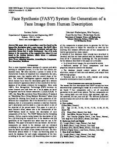
Fig. 15 Objective function values of the ten Pareto optimal solutions for global bending. „a… number of modules and force on welds, and „b… number of welds and manufacturing cost.
and wagon models, where a downward force of 8.0 关kN兴 is applied in the middle of the floor as indicated by an arrow. Since the loading is symmetric with respect to x-z plane, half models are also used for the finite element analyses. Figure 15 show the objective function values of ten Pareto optimal solutions obtained as a result of the multi-objective optimization, where the horizontal axis indicates the solution 1D 共1–10兲. The plots illustrate rather complex trade-off between the objective functions. For instance the total force on welds can be reduced by both choosing the right joint locations and types that have low tensile forces or by simply using smaller number of welds in the structure. However, the selection of the joint location is also affected by the manufacturing cost and the manufacturability constraint. Module identification is another factor that attempts to preserve certain components and joints, likely pushing the design away from the structurally optimal solution. While the components smaller than a prescribed minimum size are excluded from module identification, the current approach makes no distinction between the modules with different manufacturing costs. If complex and hence costly modules are favored more, the trade-off among objectives might change. This issue will be addressed in the future work. Using the graphical representation of lap and butt welds in Fig. 16, two representative designs, solutions 2 and 10 in Fig. 15, are shown in Figs. 17 and 18, respectively. Solution 2 has zero modules, the smallest force on weld, the largest number of welds, and
Fig. 16 Graphical representation of „a… a lap weld and „b… a butt weld in the decomposition results.
Transactions of the ASME
Fig. 17 Decomposition results for solution 2 in the global bending condition.
relatively low manufacturing cost. It can be seen that low manufacturing cost is accomplished by small components, whose joint designs are optimized for the low force on welds. However, the resulting decompositions are very different between two structures, leading to zero sharable modules. On the other hand, solution 10 has the most modules 共4兲, moderate force on welds, small number of welds, and the highest manufacturing cost. Seemingly conflicting goals, a large number of modules and low forces on welds, are simultaneously achieved by sharing relatively large components with a fewer welds, which however caused the increase in the manufacturing cost. If the modularity criterion is important for the designer, this solution might be the preferred one if high manufacturing cost can be tolerated. It is also observed that lap joints are predominant in all Pareto optimal designs. This is because there are many members parallel to x-y-plane on the tensile side of bending 共lower half of the structure兲, for which butt joints would be subject to almost pure tensile force. This resulted in consistently low forces on welds across all Pareto optimal solutions in Fig. 15共a兲.
Fig. 19 Global torsion condition on „a… sedan model and „b… wagon model. Upward and downward forces of 4000 †N‡ each are applied at the locations indicated by two arrows.
sedan and wagon models, where upward and downward forces of 4000 关N兴 each are applied on the sides of the front frames, as indicated by arrows. Note that this loading condition leads to completely opposite force distributions on each side of the x-z plane. Since the structural strength criterion in Eq. 共6兲 is based on the tensile force at each joint, this implies the best decomposition on one side of symmetry is the worst on the opposite side. In order to identify a decomposition that performs well on both sides rather than the best on one side and the worst on another, tensile force at joint F"n in Eq. 共6兲 must be replaced with the worse between both sides: max兵 Fi "ni ,Fˆi "nˆi 其 ⫽max兵 Fi "ni ,⫺Fi "ni 其 ⫽ 兩 Fi "ni 兩
(13)
4.2 Decomposition Under Global Torsion. Figure 19 shows the boundary conditions of the global torsion case of the
where Fˆ"nˆi is the tensile force at joint i on the opposite side of symmetry. Plugging this in Eq. 共6兲 yields
Fig. 18 Decomposition results for solution 10 in the global bending condition. Identified modules are annotated with ‘‘s.’’
Fig. 20 Objective function values of the ten Pareto optimal solutions for global torsion. „a… number of modules and force on welds, and „b… number of welds and manufacturing cost.
Journal of Mechanical Design
MARCH 2004, Vol. 126 Õ 241
Since the modules are larger than a prescribed minimum size, the larger number of modules tends to increase the manufacturing cost. Similar to the global bending case, lap welds are preferred to butt welds in all Pareto optimal designs. This is because members parallel to x-axis experience axial forces 共force in x-direction兲, for which butt joints would be subject to almost pure normal force.
5
Fig. 21 Decomposition results for solution 1 in the global torsion condition. Identified modules are annotated with ‘‘s.’’
N welds
f s 共 x,y 兲 ⫽w 1
兺
i⫽1
N welds
max兵 0,兩 Fi "ni 兩 其 ⫽w 1
兺
i⫽1
兩 Fi "ni 兩
(14)
Equation 共14兲 is used instead of Eq. 共6兲 in the results given in Fig. 20, where the objective function values of 10 Pareto optimal solutions are shown. Since forces normal to the mating planes of joints, whether compressive or tensile, are added the total force on welds, the Pareto optimal solutions have consistently higher force values than the ones for global bending. Since joints are almost always discouraged with the use of Eq. 共14兲, reducing the number of welds seems the best solution to reduce the force on welds. However, the results in Fig. 20 shows no considerable reduction of forces on welds is seen between solution 1 共64 welds兲 and solutions 2–10 共75–76 welds兲, which suggests the designer not to consider strength criterion as a priority in decision-making. Figures 21 and 22 illustrate two representative solutions, solutions 1 and 10, respectively. Solution 1 has both the smallest number of welds and the lowest force on welds, but shares only one module. Solution 10, on the other hand, has the maximum number of modules and manufacturing cost with larger number of welds.
Fig. 22 Decomposition results for solution 10 in the global torsion condition. Identified modules are annotated with ‘‘s.’’
242 Õ Vol. 126, MARCH 2004
Discussion and Future Work
This paper discussed a method for modular design of structural products such as automotive bodies, where two structural products are simultaneously decomposed to components considering the structural performances of each structure and the component sharing between two structures. The problem is posed as an optimization to minimize the reduction of structural strength due to the introduction of spot-weld joints and the number of redundant joints, while maximizing the manufacturability of the component and component sharing between two structures. This multiobjective optimization problem is solved by using a genetic algorithm. Case studies demonstrate that the method successfully finds a set of acceptable solutions, with different influences of objective functions, from which a human designer can choose the best solution with respect to some specific preferences/requirements. While the decomposition of two structures is discussed for simplicity, the method can be easily extended to the assembly synthesis of more than two products. The envisioned future work is summarized below: • While the four joint types in Fig. 3 cover basic joint variations found in many automotive bodies, it is obviously not exhaustive. In particular, it does not include the joints with multiple joining planes common between the components carrying large loads 关18兴. Therefore, inclusion of more joint types into the current joint ‘‘database’’ would be desired to enhance the applicability of the method. • Although the 3D beam models used in the case study can provide useful insights to real automotive body designs, they are yet too simplified. Case studies with more detailed body models consisting of beams and plates would be desired to improve the applicability of the obtained results. It should be noted, however, that the current method can be applied to such beam-plate integral models with no modification, as long as product topology graphs are properly constructed and a joint library 共like the one in Fig. 3兲 is appropriately designed. • The present method takes module formation as a premise but not as an outcome. In other words, it simply tries to maximize the number of shared components, not the benefit resulted from component sharing. However, an effective design tool should be able to quantify the benefit 共perhaps in dollar amount兲 of component sharing to allow the designer to make trade-offs with other design criteria. This will require the development of cost models for component sharing and is sought as the next major research direction. Although the paper focused on sheet metal parts manufactured by stamping and joined by spot welding, other production and assembly methods can be incorporated by modifications in variables, constraints and objective functions. In particular, the application to the aluminum space frame body architectures 关33兴 would be of strong engineering interest due to their increasing popularity in the automotive industry. Since the space frame bodies are naturally modeled as a network of beams, the present method can be easily extended, given a realistic joint library and joint characteristics. Since aluminum space frames are typically joined with MIG welds 共stronger than beams themselves but costs more than spot welds兲 new design criteria should be developed to account for the different joint types. Manufacturability criteria should also be modified as component beams are typically hydro-extruded and hence do not allow nonlinear topologies. For space frame bodies, modularity analysis can potentially lead to many possibilities for component sharing due to the homogeneity of components. It is Transactions of the ASME
therefore of interest to investigate the opportunities for sharing components within a structure, rather than among multiple structures. The present method can be used with minimum modification for this self-sharing with or without component sharing among product variants.
Acknowledgments
关13兴 关14兴
关15兴
The first author has been partially supported by the National Science Foundation under CAREER Award 共DMI-9984606兲, the Horace H. Rackham School of Graduate Studies at the University of Michigan, and General Motors Corporation through General Motors Collaborative Research Laboratory at the University of Michigan. These sources of support are gratefully acknowledged. The authors thank Dr. Donald Malen for valuable comments on the typical joint types during the early stage of the work, and Dr. Shinji Nishiwaki and Mr. Yasuaki Tsurumi for providing us with the body models. Special thanks to Byungwoo Lee and Karim Hamza for the visualization of the results using ACIS and development of the multi-objective genetic algorithm code, respectively. Any opinions, findings, and conclusions or recommendations expressed in this material are those of the authors and do not necessarily reflect the views of the National Science Foundation.
关21兴
References
关22兴
关1兴 Blackenfelt, M., and Stake, R. B., 1998, ‘‘Modularity in the Context of Product Structuring-A Survey,’’ Proceedings of the 2nd NordDesign Seminar, 26 –28 Aug, KTH, Stockholm, Sweden. 关2兴 Kota, S., Sethuraman, K., and Miller, R., 2000, ‘‘A Metric for Evaluating Design Commonality in Product Families,’’ ASME J. Mech. Des., 122共4兲, pp. 403– 410. 关3兴 Muffatto, M., and Roveda, M., 2000, ‘‘Developing Product Platforms: Analysis of the Development Process,’’ Technovation, 20, pp. 617– 630. 关4兴 Sundgren, N., 1999, ‘‘Introducing Interface Management in New Product Family Development,’’ Journal of Product Innovation Management, 16共1兲, pp. 40–51. 关5兴 Gupta, S., Das, D., Regli, W. C., and Nau, D. S., 1997, ‘‘Automated Manufacturability: A Survey,’’ Res. Eng. Des., 9共3兲, pp. 168 –190. 关6兴 Yu, J. C., Krizan, S., and Ishii, K., 1993, ‘‘Computer-aided Design for Manufacturing Process Selection,’’ Journal of Intelligent Manufacturing, 4, pp. 199– 208. 关7兴 Yetis, A., and Saitou, K., 2001, ‘‘Decomposition-Based Assembly Synthesis Based on Structural Considerations,’’ ASME J. Mech. Des., 124, pp. 593– 601. 关8兴 Cetin, O. L., and Saitou, K., 2001, ‘‘Decomposition-based Assembly Synthesis for Maximum Structural Strength and Modularity,’’ Proceedings of the 2001 ASME Design Engineering Technical Conferences, Pittsburgh, Pennsylvania, September 9–12, DETC2001/DAC-21121. An extended version accepted to ASME Journal of Mechanical Design. 关9兴 Cetin, O. L., Saitou, K., Nishigaki, H., Nishiwaki, S., Amago, T. and Kikuchi, N., 2001, ‘‘Modular Structural Component Design Using the First Order Analysis and Decomposition-Based Assembly Synthesis,’’ Proceedings of the 2001 ASME International Mechanical Engineering Congress and Exposition, November 11–16, New York, New York. 关10兴 Fujita, K., and Yoshida, H., 2001, ‘‘Product Variety Optimization: Simultaneous Optimization of Module Combination and Module Attributes,’’ Proceedings of the 2001 ASME Design Engineering Technical Conferences, DETC01/ DAC-21058, September 9–12, Pittsburgh, PA. 关11兴 Zugasti, J. P. G., Otto, K. N., and Baker, J. D., 2001, ‘‘Assessing Value in Platformed Product Family Design,’’ Res. Eng. Des., 13共1兲, pp. 30– 41. 关12兴 Nelson, S., Parkinson, M. B., and Papalambros, P. Y., 2001, ‘‘Multicriteria
Journal of Mechanical Design
关16兴 关17兴 关18兴 关19兴 关20兴
关23兴 关24兴 关25兴 关26兴
关27兴
关28兴 关29兴
关30兴 关31兴 关32兴 关33兴
Optimization in Product Platform Design,’’ ASME J. Mech. Des., 123共2兲, pp. 199–204. Simpson, T. W., Maier, J. R. A., and Mistree, F., 2001, ‘‘Product Platform Design: Method and Application,’’ Res. Eng. Des., 13共1兲, pp. 2–22. Simpson, T. W., and D’Souza, B., ‘‘Assessing Variable Levels of Platform Commonality within a Product Family using a Multiobjective Genetic Algorithm,’’ Proceedings of the 9th AIAA/ISSMO Symposium on Multidisciplinary Analysis and Optimization, AIAA 2002–5427, Atlanta, Georgia, September 4 – 6, 2002. Fellini, R., Kokkolaras, M., Perez-Duarte, A., and Papalambros, P. Y., ‘‘Platform Selection under Performance Loss Constraints in Optimal Design of Product Families,’’ Proceedings of ASME DETC’02 Design Engineering Technical Conference, DETC2002/DAC-34099, Montreal, Canada, September 29– October 2, 2002. Messac, A., Martinez, M. P., and Simpson, T. W., 2002, ‘‘Introduction of a Product Family Penalty Function Using Physical Programming,’’ ASME J. Mech. Des., 124共2兲, pp. 164 –172. Bosa´k, J., 1990, Decompositions of Graphs, Kluwer Academic Publications, Boston. Brown, J., Robertson, J., and Serpento, S., 2002, Motor Vehicle Structures, Concepts and Fundamentals, Society of Automotive Engineers 共SAE International兲 Publications. Hahn, O., Gieske, D., Klasfauseweh, U., and Rohde, A., 1997, ‘‘Fatigue Resistance of Spot Welds under Multiaxial Loads,’’ Weld. World, 37共5兲, pp. 15– 22. Radaj, D., 2000, ‘‘Fatigue Assessment of Spot Welds based on Local Stress Parameters,’’ Weld. Res. Supplement, February pp. 52–53. Davidson, J. A., ‘‘Design-Related Methodology to Determine the Fatigue Life and Related Failure Mode of Spot-Welded Sheet Steels,’’ SAE Technical Papers, No. 8306 –022, pp. 539–551. Boothroyd, G., Dewhurst, P. and Knight, W., 1994, Product Design for Manufacture and Assembly, Marcel Dekker, New York. Skiena, S. S., 1998, The Algorithm Design Manual, TELOS/Springer-Verlag, New York. Hopcroft J. E., and Wong J. K., 1974, ‘‘Linear Time Algorithm for Isomorphism of Planar Graphs,’’ Proceedings of the Sixth Annual ACM Symposium on Theory of Computing, pp. 172–184. Srinivas, N., and Deb, K., 1994, ‘‘Multi-Objective Function Optimization using Non-Dominated Sorting Genetic Algorithms,’’ Evol. Comput., 3共2兲, pp. 221–248. Deb. K., Agrawal, S., Pratab, A., and Meyarivan, T., 2000, ‘‘A Fast Elitist Non-Dominated Sorting Genetic Algorithm for Multi-Objective Optimization: NSGA-II,’’ Proceedings of the Parallel Problem Solving from Nature VI Conference, Paris, France, pp. 849– 858. Springer, Lecture Notes in Computer Science No. 1917. Lyu, N., and Saitou, K., 2003, ‘‘Topology Optimization of Multi-Component Structures via Decomposition-Based Assembly Synthesis,’’ Proceedings of the 2003 ASME Design Engineering Technical Conferences, Chicago, Illinois, September 2– 6, DETC2003/DAC-48730. Globus, A., Lawton, J., and Wipke, T., 1999, ‘‘Automatic Molecular Design using Evolutionary Techniques,’’ Nanotechnology, 10共3兲, pp. 290–299. Hobbs, M. H. W., and Rodgers, P. J., 1998, ‘‘Representing Space: A Hybrid Genetic Algorithm for Aesthetic Graph Layout,’’ FEA 1998, Frontiers in Evolutionary Algorithms, Proceedings of the Fourth Joint Conference on Information Sciences, Research Triangle Park, NC, Vol. 2, pp. 415– 418. Fanjoy, D. W., and Crossley, W. A., 2002, ‘‘Topology Design of Planar CrossSections With a Genetic Algorithm: Part 1–Overcoming the Obstacles,’’ Eng. Optimiz., 34共1兲, pp. 1–22. Kane, C., and Schoenauer, M., 1996, ‘‘Genetic Operators for TwoDimensional Shape Optimization,’’ Lect. Notes Comput. Sci., 1063, pp. 355– 369. Cross, A. D. J., Wilson, R. C., and Hancock, E. R., 1997, ‘‘Inexact Graph Matching using Genetic Search,’’ Pattern Recogn., 30共6兲, pp. 953–970. Malen, D., and Kikuchi, N., 2002, Automotive Body Structure-A GM Sponsored Course in the University of Michigan, ME599 Coursepack, University of Michigan.
MARCH 2004, Vol. 126 Õ 243