zation method as a gray-scale image. In Phase II, the image is .... the Horace H. Rackham School of Graduate Studies at the Uni- versity of Michigan.
O. L. Cetin* Graduate Student Research Assistant
K. Saitou Associate Professor Department of Mechanical Engineering, University of Michigan, Ann Arbor, MI 48109
1
Decomposition-Based Assembly Synthesis for Maximum Structural Strength and Modularity This study presents a systematic decomposition process to carry out assembly synthesis as a tool during the conceptual design phase of a product. Two configurations obtained by structural topology optimization are decomposed automatically into assemblies consisting of multiple members with simpler geometries. Generating topology graphs for both products, the search for an optimal decomposition can then be posed as a graph partitioning problem. Considering the complexity and the corresponding computational overhead of the problem, a steady-state genetic algorithm is employed as the optimization method. The final objective function attempts to find a solution that brings about two structures with maximum structural strength, maximum assemblability, and one or more components that can be shared by both products. The software implementation is carried out and a bicycle frame design problem is solved using the procedure. It is observed that the algorithm manages to find an acceptable solution, allowing the commonality of one component in both end products and still maintaining a good structural strength and assemblability. 关DOI: 10.1115/1.1667890兴
Introduction
Product design is a process in which many product attributes such as cost, performance, manufacturability, safety, and consumer appeal are considered together. Thus, in virtually all cases, designers are forced to make trade-offs among competing criteria. At each stage of the design cycle, solutions are evaluated and reevaluated in the light of a diverse ensemble of objectives. The time and cost involved in making engineering changes increase rapidly as the product development process evolves. Early anticipation and avoidance of manufacturing and assembly problems can have a huge impact in reducing the product development time 关1兴. Most structural products are manufactured through assembly of various components which have simpler geometries than the end product. The decision of which components are better to assemble together to achieve a certain end product is defined as assembly synthesis 关2兴. Since assembly is typically the final major manufacturing process, it can bring to light problems that arise at earlier stages in the manufacturing system 关3兴. During conceptual design, teams of designers generally begin to develop a new product by sketching its general shape on paper. This ‘‘back of the envelope’’ approach is a key aspect of the creative thought process. As a tool for the engineers during this brain-storming period, this project, based on our earlier work 关2–5兴, aims at achieving a systematic decomposition process to carry out assembly synthesis. The presented approach intends to provide the designer with feedback about possible decompositions prior to the detailed design phase. The main contribution of our research to the existing method is that, now the developed software is capable of evaluating several products for modularity, in addition to the optimization of structural strength and assemblability 共ease of assembly兲 in each design.
2
Previous Work
The work on structural optimization started with proportioning the dimensions of the structures, and then advanced to varying * Currently Research Associate, Engineering Design Centre, Cambridge University, UK. Contributed by the Design Theory and Methodology Committee for publication in the JOURNAL OF MECHANICAL DESIGN. Manuscript received July 2001; rev. May 2003. Associate Editor: Linda Schmidt.
244 Õ Vol. 126, MARCH 2004
geometry of structures 共such as nodal coordinates of skeletal structures兲 for an optimum design. Both rigorous and heuristic methods for topology optimization, i.e., the techniques that involve changing the entire design topology 共for instance the number of holes in a structure兲 have developed quickly after early 1980’s 关6,7兴. Modern structural topology design methods enable top-down synthesis of an optimal structure that fits within a specified design domain from the specification of loading and boundary conditions 关2兴. For instance, Bendsoe and Kikuchi 关8兴 used the homogenization method to solve for the optimal material distribution with a specified amount of material, for the stiffest topology. Chapman et al. 关9兴 describe genetic algorithm 共GA兲 based structural topology optimization of finely discretized design domains. Shea and Cagan 关10兴 present the shape annealing method, which uses shape grammar rules with the simulated annealing algorithm to perform shape optimization of trusses. Starting with a random initial structure, topology exploration occurs by applying topology modification rules that transform configurations in the current design; metrics for design performance determine the search direction in the simulated annealing algorithm. Transforming the results of the topology optimization process into manufacturable objects is an important problem, and recently attracted interest from structural optimization researchers. Chirehdast et al. 关6,7兴 describe an additional design phase after achieving the optimal topology a frame 共beam兲 model is fit onto the mesh generated by the homogenization method and cross sections of the beams are designed using a continuous optimization method. Chang and Tang 关11兴 present an integrated design and manufacturing system that starts from a primitive concept stage, followed by a topology optimization for an initial structural layout. The results are then imported into a CAD system to construct parametric solid models for detailed shape optimization with the criteria of minimum manufacturing cost. Another critical task when adapting the topology results to real-life objects is the design of component interconnections, namely joints. Several researchers investigated the integration of topology optimization of multi-component structures 关12–15兴. These approaches, however, requires predefined design domains for components and joints as an input. Even though we get inspiration from the extensive work on topology optimization, we see that the essential problem of decomposing complex products into simpler components for assem-
Copyright © 2004 by ASME
Transactions of the ASME
bly has not been addressed. In this study, the optimal locations and attributes of the joints, together with the identification of the modules for potential sharing, are addressed by simultaneously decomposing the multiple structures obtained via structural topology optimization. The optimum topology of structures, therefore, is the input to the developed method, rather than the end result. In this regard, our method has more common roots with assembly sequence planning applications, which has been an active research field during the past decade. In most of the solutions for assembly sequence generation, the geometric model of an assembly is created by describing the components and the spatial relationship among them 关16兴. In recent years, features that combine geometric and functional information have been introduced in modeling and planning for manufacturing of parts. An integrated object-oriented product model is introduced by van Holland and Bronsvoort 关17兴 for modeling and planning of both single parts and assemblies. Wang and Bourne 关18兴 describe an integrated system for the design and production of sheet metal parts. They automatically generate some features for the sheet metal bending process as the design progresses. After the designs are complete, an automatic process planning system uses the features and generates new ones to aid the production of plans with near minimum manufacturing costs. Most algorithms cited in the literature solve assembly problems by graph searching. Each joining of a component to another component or to a subassembly is called a liaison. The general approach is building a liaison diagram and generating all possible subassemblies by decomposing the graph 共also called ‘‘cut-set’’ algorithms兲. Then the possible assembly sequences are evaluated based on the given constraints to determine the most suitable one 关1,19兴. Such an exhaustive searching method requires substantial computational resources even for a simple structure. As a computational tool, GAs have proved successful in solving combinatorial and complex problems, such as finding a near-optimal assembly plan, with a reasonable execution time 关20,21兴. In addition to the structural strength and assemblability criteria incorporated in the objective function in assembly synthesis, which was tested and verified in the earlier work 关2兴, a measure of modularity is evaluated in this study. Modularity is commonly associated with the division of products into smaller building block, modules, and involves architecting a family of products that share inter-changeable components. The benefit of part commonality is that, the effort and resources invested for the design of one module are not considered again, if the component fits another product. Modularity not only enables simultaneous work in the product development, but the manufacturing process may also be performed in parallel, so lead-times can be reduced 关22兴. Ishii 关23兴 reports that modularity in product design impacts every stage of the product life-cycle, and also affects serviceability and recyclability in terms of disassembly, separation, repair, and reprocessing. He introduces a set of metrics and design charts that aid in enhancing life-cycle modularity of product families and generations. Delayed product differentiation concept, as discussed by He et al. 关24兴 addresses part commonality at an early stage of a manufacturing process; it is proved in their work that modular design may decrease inventory, manufacturing and material handling costs. Conner et al. 关25兴 also address economy-of-scalerelated aspects of product families, including ease of assembly and manufacture. Newcomb et al. 关26兴 developed a method employing a commonality table for the entire product family to identify the effects of a product platform. They determine the commonality indices for the different members of the family for different viewpoints and then combine the measures for the members of the product family to achieve an overall platform index. Kota et al. 关27兴 follow a similar approach and present an objective measure called the Product Line Commonality Index, to capture the level of component commonality in a product family. They suggest seeking Journal of Mechanical Design
functional design features based on configuration similarities 共e.g., geometric shapes兲, kinematic similarities 共e.g., joint types and motion兲, actuation similarities and the like. In addition to product driven concerns, Yu et al. 关28兴 introduce a customer need basis for defining the architecture of a portfolio of products. To study modularity based design decisions quantitatively, a multicriteria optimization problem is formulated by Nelson et al. 关29兴; they analyze Pareto sets that correspond to various derivative products to develop a systematic product platform design methodology. Another approach to set up a mathematical framework for modular architecture is introduced by Fujita et al. 关30兴; they formulate a 0-1 integer programming problem to assess module commonalization.
3
Assembly Synthesis Method
Although proven to be effective, the approaches in the assembly planning literature require pre-decomposed component geometry as input, hence limiting their application to early phases of the design process when such a decomposition is not yet available; it is aimed to overcome this limitation in this project. In the current approach, a structure obtained via structural topology optimization is decomposed automatically into an assembly consisting of multiple structural members with simpler geometries. There are two main steps in the process developed 关5兴: 1. A two-dimensional bitmap image of a structure obtained via structural topology optimization is transformed to a product topology graph through application of image processing algorithms. 2. The product topology graph is decomposed into subgraphs by using a genetic algorithm which results in a decomposition of the product with chosen mating features. During the product topology graph generation, members of the structure are mapped to nodes and the intersections are mapped to multiple edges since they can be joining more than two members. The search for optimal decomposition can then be posed as a graph-partitioning problem, a discrete optimization task, as the problem is defined over a set of discontinuous states 共edges to be cut by a partition兲. In summary, the problem is given the topology graph of the structure, obtain the partition representing the optimal decomposition and the mating feature for each joint, subject to a cost function evaluating the decomposition quality. The objective function to evaluate each decomposition can be chosen in the light of the guidelines for Design of Manufacturing 共DFM兲 and Design for Assembly 共DFA兲 methods in the literature. Typical examples are 关31兴: • Maximize standardization 共materials, design concepts, components, tools, fixtures, modular design兲 • Select solutions that simplify manufacturing 共shape, composition etc.兲 • Choose solutions that enhance uniformity and parallelism • Minimize the number of required resources In the current problem it is decided that joining method at every joint is assigned as spot weld and the only joint feature considered is the weld angle which is chosen from discrete set of possible values. Welding orientation is an important factor in the design and manufacturing of weld products. Welding orientation selection must be made at the early stages of the design process so that necessary design changes can easily be made to achieve an optimal design solution; consequently other design tasks, such as fixture design, can be completed in parallel 关32兴. Since spot weld joints are much weaker against tensile loads than against shear loads 关33兴, to evaluate the decomposition according to the structural strength criteria, the normal stress at the joints and the area on which the normal stress acts are calculated. The evaluation is based on the difference between the angle at which the normal stress is minimum ( ideal) and the chosen mating angle; note that deviation from the ideal angle means higher MARCH 2004, Vol. 126 Õ 245
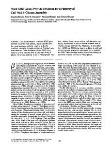
Fig. 1 The design problems to be addressed simultaneously
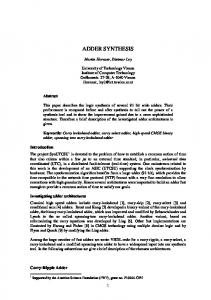
normal stress. So in this formulation maximum structural strength is achieved when there is no weld 共no decomposition case兲 or when none of the welds are under tensile stress. Consequently the reduction in structural strength is defined as the sum of normal stresses on all welds, which should be minimized. When assemblability is considered, the similarity of weld angles and the number of welds in the decomposition are taken into account. Along the line of DFM and DFA rules, it is assumed that lower number of welds is preferred to simplify the assembly process and minimize the required resources. Similar weld angles are favored to end up with higher uniformity and parallelism in the design. The modularity criteria proposed in this work is implemented by analyzing two structures at a time, and assessing the similarity of the disconnected components to point at a probable part commonality. A term is added to the objective function to favor the decompositions that result at: a兲 components with similar stress states, represented by the joint angles, b兲 components that are geometrically similar to each other, by considering the lengths and thicknesses of their corresponding members, or by using an equivalent measure of shape similarity. Also, before evaluating the cost function component related to modularity, it is certified that the subgraphs of the components to be shared are isomorphic; note that this is necessary but not sufficient condition for two structures to be assembled in the same way. Thus the final objective function attempts to find a solution that results in two decompositions with maximum structural strength, maximum assemblability, and one or more components that can be shared by the both designs. To be used as an illustrative case throughout this section, let us consider the two simple structural design problems given in Fig. 1: note that the only the difference between 共a兲 and 共b兲 is the application point of the concentrated force P⫽1000 N. The structural topology optimization method is applied to the two design domains in Fig. 1 to obtain the stiffest structures occupying a desired fraction 共40% in Fig. 2兲 of the design domains. In the following examples, the publicly available Web-based topology optimization software1 based on the ‘‘density method’’ of topology optimization 关34兴 is used for this purpose. After thresholding the results, the topologies presented in Figure 2 are obtained. The problem is to find two optimal decompositions for Figs. 2共a兲 and 共b兲, so that the maximum structural strength for both structures are maintained, and at the same time some components are shared by the products. 3.1
Mathematical Model
3.1.1 Definition of the Design Variables. Let the members of the structure be mapped to the nodes of the product topology graph and the intersections be mapped to the edges. This mapping 1
Developed at the Technical University of Denmark: www.topopt.dtu.dk
246 Õ Vol. 126, MARCH 2004
Fig. 2 Optimum topologies for the design problems
is done automatically using the image processing tools2 developed by Yetis and Saitou 关5兴, which is an improvement of the graph extraction algorithm by Chirehdast 关7兴. The graph representation for the optimum topology of the first design problem is given in Fig. 3共b兲 as an example. So the whole structure can be represented as G⫽(V,E) with a node set V and an edge set E. The problem of optimal decomposition becomes one of finding a partition, i.e., the design variable P, of the node set V such that the objective function, c( P), is maximized. Mating features at the joints are to be used to assess the structural strength of the members: therefore a set, F, of joint features must be defined to be able to evaluate different decompositions. Based on assumptions in the earlier work, F is the set of possible mating angles at the welded joints. The optimal partitioning of G can be represented mathematically by a vector x⫽(x 1 ,x 2 , . . . ,x 兩 E 兩 ) where x i is a binary variable representing the presence of edge e i in the decomposition defined by the partitioning P. Another vector y ⫽(y 1 ,y 2 , . . . ,y 兩 E 兩 ) is defined to store the mating features for each edge e i ; note that domain of y depends on the model of the joint represented by the edge. As an illustration of the concept, consider Fig. 3共c兲, where a certain partitioning is depicted; all the marked edges are cut in the graph, and the ones with a circular spot are to be welded 共also shown as dashed lines in the second part of Fig. 3共c兲兲. Figure 3共d兲 presents the corresponding decomposition. 3.1.2 Definition of the Constraints. The constraint on the vector x, which represents the presence of edges, is the following: COMPONENTS共 GRAPH共 x 兲兲 ⫽k
(1)
where • GRAPH(x) returns the graph after the edges with x i ⫽0 in vector x, have been removed from the original topology graph, • COMPONENTS(G) returns the number of disconnected components in graph G, • k denotes the desired number of components specified by the user. The constraint on vector y is as follows: y i 苸F
(2)
where F is the set of mating angles at which spot welds can be applied at the joints. One element of set F represents the case for no weld at the corresponding joint. Another constraint is imposed on the combination of the vectors x and y in the following way: IS – CONNECTED共 COMBINED – GRAPH共 x,y 兲兲 ⫽1
(3)
where 2 LEDA library developed at the Max-Planck Institute of Computer Science is used for the graph algorithms.
Transactions of the ASME
blability criteria, the similarity of weld angles and the number of welds in the decomposition are taken into account. Obviously, lower number of welds and similar weld angles result in higher assemblability. These criteria result in the following objective function component for structural considerations: N welds
f s 共 x,y 兲 ⫽w 1
兺
i⫽1
N welds
共 i ⫺ iideal兲 2 ⫹w 2
兺
i⫽1
共 i 共 i 兲 A i 共 i 兲兲
N welds N welds
⫹w 3
兺 兺 i⫽1
j⫽i⫹1
共 i ⫺ j 兲 2 ⫹w 4 N welds
(4)
The variables are defined as follows: x⫽(x i ) x i is a binary variable representing the presence of edge e i in subset x y⫽(y i ) y i is discrete variable representing the choice of weld angle at joint i wi weight of i-th criteria in the objective function N welds total number of welds in the decomposed structure i weld angle with respect to vertical direction at joint i iideal angle of minimum normal stress at joint i i ( i ) normal stress at joint i at angle i A i ( i ) weld area at joint i 共function of i ) As the second part of the objective function, the cost function for modularity is incorporated to evaluate two attributes of the components to be shared between the structures: 1. Similarity in stresses that the components are subject to: this condition is simply implemented by maintaining that joint angles of the components should be close to each other, 2. Similarity in shapes of the components in a given 共userspecified兲 tolerance: this attribute is checked by comparing the components with respect to their areas.
Fig. 3 Graph representation for problem 1
• IS – CONNECTED(G) is a function which returns 1 if the graph G is connected and returns 0 otherwise. • COMBINED – GRAPH共x,y兲 is a function that returns a graph which consists of the nodes of the original graph and the edges in vectors x, y. This constraint ensures that the combination of the decomposition given by vector x and the mating angles given by vector y constitutes a structure which has the same connectivity as the original disconnected structure. 3.1.3 Definition of the Objective Function. Objective function will evaluate each decomposition according to the following criteria: • Reduction of structural strength due to introduction of joints • Assemblability of the decomposed structures • The maximum modularity of the structures To evaluate the decomposition according to the structural strength criteria, the normal stress at the joints and the area on which the normal stress acts are calculated. The evaluation is based on the difference between the angle at which the normal stress is minimum, iideal , and the chosen welding angle given by vector y, as deviation from the ideal angle means higher normal stress. The stress at the chosen angle multiplied by the weld area provides a measure of force acting on the weld which is also used in evaluating the decrease in strength. A weld with larger area introduces a higher amount of decrease in strength than a weld with smaller area. While assessing the decomposition with respect to the assemJournal of Mechanical Design
Note that this procedure requires that all components that come out of the decomposition process of one structure be compared with the components in the second design problem. However, probably only a few of the components at each iteration will have the same number of members assembled in a similar manner. Thus, before evaluating how similar two components are, it is convenient to test if the corresponding subgraphs are isomorphic: the modularity cost function should return a large number if no components are found to be isomorphic, and if this check is passed, then the similarity measure can be applied. Considering the computational overhead of this check, a simple approximation, actually a necessary but not sufficient condition is utilized in the software: it is required that the components have an equal number of nodes and edges to be shared. A fast graph isomorphism check algorithm will be employed for more complex design problems in the future work. Thus the modularity component of the objective function is implemented as follows: function f m (x1 ,y1 ,x2 ,y2 ) 1. cost⫽0 2. for each pair of subgraphs (g k1 ,g l2 ) 3. if Is – Isomorphic(g k1 ,g l2 )⫽TRUE 4. 5.
N
c
welds (( 1 ) i ⫺( 2 ) i ) 2 ⫹w 6 h(g k1 ,g l2 ) cost⫽cost⫹w 5 兺 i⫽1 else cost⫽cost⫹a large number return cost (5)
where • g k1 and g l2 are two subgraphs representing the component in structures 1 and 2 decomposed as specified in x1 , y1 and x2 , y2 , respectively. • Superscripts k and l are the indices of subgraphs in each structure. • w 5 and w 6 are the weights for the corresponding criteria, MARCH 2004, Vol. 126 Õ 247
• ( 1 ) i and ( 2 ) i are the weld angles at joint i of each component, c is the number of welds in the shared components, • N welds • Is – Isomorphic(g k1 ,g l2 ) is a function that returns TRUE if subgraphs g k1 , g l2 are isomorphic, FALSE otherwise. For the time being the function only checks if the two subgraphs have the same number of nodes and edges. Therefore the size of the combinatorial problem that results from checking each pair of subgraphs from the structures decreases considerably. • h(g k1 ,g l2 ) is a function that returns a measure of geometric similarity between the components. This measure is realized by the calculation of first moments of component areas with respect to origin; so the locations of the components in the configuration are also incorporated. Note that before f m (x1 ,y1 ,x2 ,y2 ) returns a cost at an iteration, all components, i.e., all subgraphs are examined, and only if none of them are isomorphic a large number is returned to introduce a penalty for lack of part commonality. In a similar manner, if more than one component in each structure match with others, the similarity measures are added up to favor the sharing of several components among the products. The constraints and objective function combine to give the following optimization problem: minimize ⫹ f m (x1 ,y1 ,x2 ,y2 )
f (x1 ,y1 ,x2 ,y2 )⫽ f s (x1 ,y1 )⫹ f s (x2 ,y2 )
subject to x1 苸 兵 0,1其 兩 E1 兩 x2 苸 兵 0,1其 兩 E2 兩 y1 苸F⫽ 兵 0,1,2,3,4 其 兩 E1 兩 y2 苸F⫽ 兵 0,1,2,3,4 其 兩 E2 兩 COMPONENTS(GRAPH(x1 ))⫽k 1 COMPONENTS(GRAPH(x2 ))⫽k 2 IS – CONNECTED(COMBINED – GRAPH(x1 ,y1 ))⫽1 IS – CONNECTED(COMBINED – GRAPH(x2 ,y2 ))⫽1 3.2 Optimization Method. The exact solution of the graph partitioning problem, even with a linear objective function, requires exponential computation 关34兴. Noting the computational overhead and high nonlinearity of the cost function, a genetic algorithm 共GA兲, is conveniently used in this project. GAs are regarded as a compromise between random and informed search methods, and they have proved very efficient in the solution of discrete optimization problems. The decomposition problem is to be solved by using a steadystate GA 关36兴. Instead of replacing all parents by their children as in conventional 共generational兲 GA, this approach involves keeping a specified percentage of the population and renewing the rest with the newly formed chromosomes. The basic flow of the algorithm is given below. Note that the fitness is assumed to be minimized: 1. Randomly create a population P of n chromosomes 共an encoded representation of design variables兲 and evaluate their fitness values and store the chromosome with the minimum fitness value. Also create an empty subpopulation Q. 2. Select two chromosomes c i and c j in P with probability proportional to ( f max⫺f i) and ( f max⫺f j), respectively, where f i and f j are the fitness value of chromosome c i and c j , and f max is the maximum fitness in P at the current generation. 3. Crossover c i and c j to generate two new chromosomes c i⬘ and c ⬘j . 4. Mutate c i⬘ and c ⬘j with a certain low probability. 5. Evaluate the fitness values of c i⬘ and c ⬘j and add them in Q. If Q contains less than m new chromosomes, go to 2. 6. Replace m chromosomes in P with the ones in Q and empty Q. Update the best chromosome and increment the genera248 Õ Vol. 126, MARCH 2004
Fig. 4 First half of chromosome with binary information
tion counter. If the generation counter has reached a prespecified number, terminate the process and return the best chromosome. Otherwise go to 2. Empirical advantages of steady-state GA are that it prevents premature convergence of population and reaches an optimal solution with fewer number of fitness evaluations 关36兴. These improvements can be attributed to the fact that child chromosomes can mate with their parents in subsequent steps of the steady-state procedure, leading to better solutions faster. The resulting children are also often checked against the remaining parents to avoid duplication and possible early domination. Each solution is encoded in a chromosome in the following way: The chromosome is of length 2 兩 E 兩 where 兩E兩 is the number of the edges in the graph. First 兩E兩 genes carry binary information about which edges of the topology graph are kept and which are removed to produce a decomposition 共Fig. 4兲. If the ith element of the chromosome is 0, it means that this edge has been cut in this particular decomposition represented by this chromosome. The second half of the chromosome carries the information about which discrete choice of possible mating angles is chosen for a given joint 共Fig. 5兲. The ( 兩 E 兩 ⫹i)th element carries the choice of mating angle for the ith joint 共edge in the graph兲. Since the procedure introduced in this project requires the simultaneous evaluation of two structures, apparently the chromosomes given in Figs. 4 and 5 cannot be used on their own. A simple way of examining two chromosomes, i.e., two partitioning problems at once is combining the chromosomes and treating the genome properly by customized crossover and mutation operations. Then the length of the chromosome becomes 2 兩 E 1 兩 ⫹2 兩 E 2 兩 , where E 1 and E 2 represent the number of edges in each structure’s topology graph. Since the customization of the operations and representations given in this section for this new application only involves the repetition of the tasks for both 1st and 2nd structures, and the implementation consists of solely changing the indices to point to the correct gene, details are avoided in this paper. For this study, the possible mating angles have been chosen as ⫺45, 0, 45, 90 degrees from the vertical and map to gene values of 1, 2, 3, 4, respectively, as given in Fig. 6. A gene value of zero means no weld at that intersection. Since chromosomes representing the decompositions carry two different kinds of information (x i is binary and y i 苸F) the crossover and the mutation operators have been customized. The crossover operator treats the first and second halves of the chromosome simultaneously since the information in the second half complements the information in the second half and only combinations of corresponding genes in the first and second halves represent a good or bad solution. Therefore application of crossover at the same point in both halves preserves the good or bad nature of the chromosome. Practically the custom crossover operator is a multipoint crossover operator 共Fig. 7兲. As genetic algorithms do not handle constraints directly, the constraints in the mathematical problem formulation have to be
Fig. 5 Second half of chromosome with mating angle information
Transactions of the ASME
Fig. 6 Possible mating angles at the joints
translated into penalty terms. Therefore, the fitness function will consist of two main terms; the objective function value f (x1 ,y1 ,x2 ,y2 ) of the decomposition and the penalty term which imposes the constraints of the mathematical model: Fitness⫽ f 共 x1 ,y1 ,x2 ,y2 兲 ⫹Penalty terms
(6)
The constraint on vectors x and y are imposed simply by the chromosome representation of the problem, i.e., genes in the first half of the chromosome are binary values imposing the constraint x i 苸 兵 0,1其 and genes in the second half of the chromosome can only have values imposing the condition y i 苸F, where F is the set of possible mating angles. The constraint on the number of components is imposed as a penalty term in the fitness function by taking the difference of the resulting number of components and the one specified by the user. Penalty⫽ 共 COMPONENTS共 GRAPH共 x兲兲 ⫺k 兲 2
(7)
Connectivity constraint is implemented by returning a fitness of infinity 共very large number in the software implementation兲 for decompositions lacking connectivity, i.e., returning 0 when passed to the IS – CONNECTED(G) function. Structurally disconnected decompositions, which are not feasible, are eliminated by this constraint straight away. 3.3 Decomposition of the Products. Using a population ranging between 200 and 300 members, and running the genetic algorithm with a termination condition of about 5000 iterations, several local minima, i.e., optimal decompositions are obtained 共Fig. 8兲. It turns out that using a small number of iterations is not enough for the system to reach a steady population. As expected, the search space is really spacious and the convergence to a different solution is highly dependent on the random initial population. Fortunately, due to the fact that the finite element analysis is performed a priori, and results are stored in a look-up table, the whole process takes around 30 seconds on a Pentium III 800 MHz computer. The fast approximate isomorphism check also contributes to the good speed of the software. So the optimization can be performed repeatedly to cover increasingly bigger areas in the search space, to ultimately reach the global optimum. The decomposition given in Fig. 8共a兲 is found to be the best solution when modularity consideration has a sufficient weight to force the designs to share a component at all times. Though the
Fig. 7 Crossover of two chromosomes
Journal of Mechanical Design
Fig. 8 The minima for the sample problem. The components marked with ‘‘s ’’ are shared among the products.
best solution agrees with the human intuition that the triangular components in the both products should be shared in some way, note that the ideal case that involves two shared components 共Fig. 8共b兲兲 has a cost nearly 50% more than the best cost in Fig. 8共a兲. So the expected ideal configuration is essentially not feasible unless the modularity measure is far more important than the structural strength and assemblability considerations. However if some manufacturability criterion was present as well, the best solution might be disregarded due to the complex shape of the second configuration. cost An important observation is that, in the modularity criteria, the term that contains the resemblance of angles cannot be made too large, i.e., the corresponding weight has an upper bound. When one tries to increase this weight to force that the shared components have similar angles, the solutions tend to avoid having part commonality. A further analysis is certainly necessary to investigate this conflict, but at this stage it will be only inferred that practically it is difficult to make the shared components have similar weld angles. To examine the effects of the modularity terms in the objective function, the earlier version of the assembly synthesis implementation as reported in 关2兴 is used, and the configurations that result from solely structural measures are presented in Fig. 9. Note that while the optimal configuration in Fig. 9共a兲 agrees with the minima found in the scope of the modularity analysis, the structural measures, when applied alone, lead to different decompositions for the second problem as can be observed by comparing Fig. 8 with Fig. 9共b兲. For further insight into the obtained solution, the ideal angles for the joints and the von Mises stress distributions for both structures are given in Fig. 10 and Fig. 11 respectively.
Fig. 9 Decompositions when only structural measures are used
MARCH 2004, Vol. 126 Õ 249
Fig. 10 Ideal angles calculated for the joints using the results of the finite element analysis
4
Case Study: Bicycle Frame Design
To demonstrate the capabilities of the method better, a real life problem is addressed as a case study. The goal in this problem is to decompose two similar bicycle frames in an optimal way. Apparently spot-welding is not the usual joining method for bicycle frames; however we apply our formulation without any modification for illustration purposes only. Figure 12 illustrates the bicycle frame design model as given by Chirehdast et al. 关6兴; with a few simplifications in the loading conditions, this model is the starting point of our example. Chirehdast et al. use a three-phase design process called Integrated Structural Optimization System 共ISOS兲. In Phase I, an optimal initial topology is created by a homogenization method as a gray-scale image. In Phase II, the image is transformed to a smoother and realizable design using computer vision techniques. In Phase III, the design is parameterized and
Fig. 13 Loads and boundary conditions for the first frame
conventional size and shape optimization methods are employed. The model in Fig. 12 is the starting point of Phase I in ISOS environment. Figure 13 presents the original loadings and the resulting optimal topology. Changing the application point of the load on the handle, taking into account the fact that some bicycle models have the handle lower than the seat, the optimal configuration given in Fig. 14 is obtained. The resulting structures are similar at first sight, but slightly different in geometry, which make them ideal candidates for a modularity analysis. Note that Fig. 13共b兲 is the same as the optimal configuration given in 关6兴 at the end of Phase II, and also very close to the customary frames offered by the industry. The von Mises stress distribution and the ideal angles as given in Fig. 15 and Fig. 16 are obtained using Abaqus, with a mesh size
Fig. 11 Stress distributions for the sample problem. Maximum stresses are 600 MPa and 500 MPa respectively for the two structures. Stress increases from dark to light regions.
Fig. 12 Bicycle frame model modified from Chirehdast et al., †6‡
250 Õ Vol. 126, MARCH 2004
Fig. 14 Loads and boundary conditions for the second frame. Application point of the „1000 N, 140 N… load is slightly changed compared to Fig. 13.
Transactions of the ASME
Fig. 16 Ideal joint angles for the frames
Fig. 15 Stress distributions for the frames. Maximum stresses are 170 MPa and 100 MPa respectively for the two structures. Stress increases from dark to light regions.
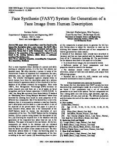
of 25 mm by 25 mm. Table 1 gives the typical GA parameters used during the optimization run. The weight values for the objective function terms are also tabulated 共Table 2兲. To better visualize the influence of the modularity terms in the objective function, the software is run initially with only structural criteria, and the decompositions presented in Fig. 17 and Fig. 18 are found to be the optimal solutions. Consequently carrying out the modularity analysis, several local optimal solutions with close costs are achieved 共Fig. 19兲. The evolution history graph depicting the change in each objective function term and visualizing the convergence of the GA is given in Fig. 20. Note that in general the resulting decompositions are similar to the analysis for structural criteria, but especially the second frame converges to a single solution to share the triangular component on the left of the structure. Another interesting observation is the shared component shown in Fig. 19共a兲, this solution would not be possible without the area-moment calculation, which evaluates geometric similarity in a rotationally invariant way.
5
Discussion and Future Work
We observe that the algorithm manages to find an acceptable solution, allowing the sharing of one component by both end products and still maintaining a good structural strength and assemblability. It may be necessary, however, to carry out the syn-
Table 1 Typical run-time GA parameters used in the case study Population size Number of generations Crossover probability Mutation probability Population replacement
200 3000 90% 1% 20%
Table 2 Typical weight values for objective function terms w1 w2 w3 w4 w5 w6
共deviation from ideal angle兲 共tensile force on welds兲 共similarity of joint angles兲 共number of welds兲 共weld angles of modules兲 共geometric similarity of modules兲
Journal of Mechanical Design
100.0 1.0 10.0 1000.0 1000.0 1.0
Fig. 17 Decomposition of frame 1 when only structural measures are used, i.e., w 5 Ä w 6 Ä0.
thesis with different objective function weights in a systematic way to have a complete understanding of the design. Note that this process is essentially equivalent to estimating the Pareto set3 in a multicriteria optimization problem. In the specific examples presented in this study, the weights are determined by trial-and-error, taking into account the relative function values; the optimal solutions are not found to be very sensitive to changes in the weights. For more complex problems this might not hold true, so this issue will be addressed more rigorously in the future. Besides the objective function weights, there are two userspecified parameters that potentially have influence on the optimization results. One is the shape similarity tolerance that is used to decide if two components are geometrically similar; it turns out the results are not very sensitive to this value. The second parameter, the desired number of components 共k兲, however, is much more critical. Though as done in the examples given in this paper, several different optimization runs with different k values are feasible, for complex problems the value could be hard to predict. Ideally the number of components should be the result of the optimization, instead of an input, which will be realized when a manufacturability criterion is implemented in the future versions of the method. The decomposition then would result in the optimal sizes of components, and consequently the optimal value for k. The approximation used instead of a formal graph isomorphism check seems to be working well, obviously introducing a faster evaluation of the objective function. However for larger graphs this approximation may not be applicable; there may be many subgraphs having the same number of nodes and edges but not having isomorphism, leading the software to incorrect module identifications. So either a better approximation or an exact isomorphism check is needed for larger scale problems. It is planned to employ exact graph isomorphism in the future applications: though this would mean exponential increase in computational overhead, it is expected that the graphs of concern will not be extremely large, so the additional computation expense is a good trade-off with accuracy. A possible research direction for the future work is applying assembly synthesis during the process of structural topology opti3 For minimization, a value y of a vector function is said to be Pareto optimal if no other value of the vector function is smaller than y in all components.
MARCH 2004, Vol. 126 Õ 251
Fig. 18 Decomposition of frame 2 when only structural measures are used. a… and b… are two alternative decompositions with close cost values.
mization, not afterwards, considerably broadening the search space for the optimal design. Another improvement may be incorporating additional objectives into the problem formulation and as a result into the fitness evaluation. Also complex modeling of joint
Fig. 20 Optimization history of a typical GA run for the bicycle design example for each objective function term: „a… f s „x1 ,y1 …, „b… f s „x2 ,y2 …, and „c… number of modules. The values shown in the plots are of the best individual for each generation.
features can be done to achieve more accurate evaluation of effect of joints on structural stiffness and strength. Ultimately, extension to 3-D structures is necessary to extend the application of the method devised in this research to real-life cases in the industry.
Acknowledgments
Fig. 19 Decomposition of the frames for modularity. The components marked with ‘‘s ’’ are shared among the products.
252 Õ Vol. 126, MARCH 2004
A partial support for this work has been provided by National Science Foundation under CAREER Award 共DMI-9984606兲 and the Horace H. Rackham School of Graduate Studies at the University of Michigan. These sources of support are gratefully acknowledged. Transactions of the ASME
References 关1兴 Mantripragada, R., and Whitney, D. E., 1998, ‘‘The Datum Flow Chain: A Systematic Approach to Assembly Design and Modeling,’’ Res. Eng. Des., 10共3兲, pp. 150–165. 关2兴 Saitou, K., and Yetis, A., 2000, ‘‘Decomposition-Based Assembly Synthesis of Structural Products: Preliminary Results,’’ Proceedings of the Third International Symposium on Tools and Methods of Competitive Engineering, Delft, The Netherlands, April 18 –21. 关3兴 Smith, R. P., 1998, ‘‘Teaching Design for Assembly Using Product Disassembly,’’ IEEE Trans. Educ., 41共1兲, pp. 50–53. 关4兴 Yetis, A., 2000, ‘‘Decomposition-based Assembly Synthesis of Structural Products,’’ Master’s thesis, Department of Mechanical Engineering, University of Michigan-Ann Arbor. 关5兴 Yetis, A., and Saitou, K., 2002, ‘‘Decomposition-Based Assembly Synthesis Based on Structural Considerations,’’ ASME J. Mech. Des., 124, pp. 593– 601. 关6兴 Chirehdast, M., Gea, H.-C., Kikuchi, N., and Papalambros, P. Y., 1994, ‘‘Structural Configuration Examples of an Integrated Optimal Design Process,’’ ASME J. Mech. Des., 116共4兲, pp. 997–1004. 关7兴 Chirehdast, M., 1992, ‘‘An Integrated Optimization Environment for Structural Configuration Design,’’ PhD dissertation, University of Michigan. 关8兴 Bendsoe, M., and Kikuchi, N., 1988, ‘‘Generating Optimal Topologies in Structural Design using a Homegenization Method,’’ Comput. Methods Appl. Mech. Eng., 71, pp. 197–224. 关9兴 Chapman, C. D., Saitou, K., and Jakiela, M. J., 1994, ‘‘Genetic Algorithms as an Approach to Configuration and Topology Design,’’ ASME J. Mech. Des., 116, pp. 1005–1012. 关10兴 Shea, K., and Cagan, J., 1999, ‘‘Languages and Semantics of Grammatical Discrete Structures,’’ Artificial Intelligence for Engineering Design, Analysis and Manufacturing, 13, pp. 241–251. 关11兴 Chang, K.-H., and Tang, P.-S., 2001, ‘‘Integration of Design and Manufacturing for Structural Shape Optimization,’’ Adv. Eng. Software, 32共7兲, pp. 555– 567. 关12兴 Johanson, R., Kikuchi, N., and Papalambros, P., 1994, ‘‘Simultaneous Topology and Material Microstructure Design,’’ Advances in Structural Optimization, B. H. V. Topping and M. Papadrakakis 共ed.兲, Civil-Comp Ltd., Edinburgh, Scotland, pp. 143–149. 关13兴 Jiang, T., and Chirehdast, M., 1997, ‘‘A Systems Approach to Structural Topology Optimization: Designing Optimal Connections,’’ ASME J. Mech. Des., 119, pp. 40– 47. 关14兴 Chickermane, H., and Gea, H. C., 1997, ‘‘Design of Multi-Component Structural Systems for Optimal Layout Topology and Joint Locations,’’ Eng. Comput., 13, pp. 235–243. 关15兴 Li, Q., Steven, G. P., and Xie, Y. M., 2001, ‘‘Evolutionary Structural Optimization for Connection Topology Design of Multi-Component Systems,’’ Engineering Computations, 18共3/4兲, pp. 460– 479. 关16兴 Eng, T.-H., Ling, Z.-K., Olson, W., and McLean, C., 1999, ‘‘Feature-based Assembly Modeling and Sequence Generation,’’ Computers & Industrial Engineering, 36共1兲 , pp. 17–33. 关17兴 van Holland, W., and Bronsvoort, W. F., 2000, ‘‘Assembly Features in Modeling and Planning,’’ Rob. Comput.-Integr. Manufact., 16共4兲, pp. 277–294. 关18兴 Wang, C.-H., and Bourne, D. A., 1997, ‘‘Design and Manufacturing of Sheet Metal Parts: Using Features to Aid Process Planning and Resolve Manufacturability Problems,’’ Rob. Comput.-Integr. Manufact., 13共3兲, pp. 281–294.
Journal of Mechanical Design
关19兴 Whitney, D. E., Mantripragada, R., Adams, J. D., and Rhee, S. J., 1999, ‘‘Designing Assemblies,’’ Res. Eng. Des., 11共4兲, pp. 228 –253. 关20兴 Senin, N., Groppetti, R., and Wallace, D. R., 2000, ‘‘Concurrent Assembly Planning with Genetic Algorithms,’’ International Journal of Product Design and Process Development, 16共1兲, pp. 65–72. 关21兴 Lazzerini, B., and Marcelloni, F., 2000, ‘‘A Genetic Algorithm for Generating Optimal Assembly Plans,’’ Artif. Intell. Eng., 14共4兲, pp. 319–329. 关22兴 Stake, R. B., 1999, ‘‘A Hierarchical Classification of the Reasons for Dividing Products into Modules-A Theoretical Analysis,’’ Licentiate thesis, Department of Manufacturing Systems, Royal Institute of Technology, Sweden. 关23兴 Ishii, K., 1998, ‘‘The Life-cycle of an Enterprise,’’ A. Molina, J. M. Sanchez, and A. Kusiak, eds., Handbook of Life-cycle Engineering, Kluwer Academic Publishers & Chapman and Hall, London ISBN: 0-412812509. 关24兴 He, D., Kusiak, A., and Tseng, T. L., 1998, ‘‘Delayed Product Differentiation: A Design and Manufacturing Perspective,’’ Comput.-Aided Des., 30共2兲, pp. 105–113. 关25兴 Conner, C. G., De Kroon, J. P., and Mistree, F., 1999, ‘‘A Product Variety Tradeoff Evaluation Method for a Family of Cordless Drill Transmissions,’’ Proceedings of the 1999 ASME Design Engineering Technical Conferences, DETC99/DAC-8625, Las Vegas, Nevada, September 12–15. 关26兴 Newcomb, P. J., Bras, B. A., and Rosen, D. W., 1998, ‘‘Implications of Modularity on Product Design for the Life Cycle,’’ ASME J. Mech. Des., 120共3兲, pp. 483– 490. 关27兴 Kota, S., Sethuraman, K., and Miller, R., 2000, ‘‘A Metric for Evaluating Design Commonality in Product Families,’’ ASME J. Mech. Des., 122共4兲, pp. 403– 410. 关28兴 Yu, J. S., Gonzalez-Zugasti, J. P., and Otto, K. N., 1999, ‘‘Product Architecture Definition Based Upon Customer Demands,’’ ASME J. Mech. Des., 129共3兲, pp. 329–335. 关29兴 Nelson, S., Parkinson, M. B., and Papalambros, P. Y., 2001, ‘‘Multicriteria Optimization in Product Platform Design,’’ ASME J. Mech. Des., 123共2兲, pp. 199–204. 关30兴 Fujita, K., Sakaguchi, H., and Akagi, S., 1999, ‘‘Product Variety Deployment and Its Optimization under Modular Architecture and Module Commonalization,’’ Proceedings of the 1999 ASME Design Engineering Technical Conferences, DETC99/DFM-8923, Las Vegas, Nevada, September 12–15. 关31兴 van Vliet, J. W., van Luttervelt, C. A., and Kals, H. J. J., 1999, ‘‘State-of-theart Report On Design for Manufacturing,’’ Proceedings of the 1999 ASME Design Engineering Technical Conferences, DETC99/DFM-8970, Las Vegas, Nevada, September 12–15. 关32兴 Yao, Z., Bradley, H. D., and Maropoulos, P. G., 1998, ‘‘An Aggregate Weld Product Model for the Early Design Stages,’’ Artificial Intelligence for Engineering Design, Analysis and Manufacturing, 12共5兲, pp. 447– 461. 关33兴 Hahn, O., Gieske, D., Klasfauseweh, U., and Rohde, A., 1997, ‘‘Fatigue Resistance of Spot Welds under Multiaxial Loads,’’ Weld. World, 37共5兲, pp. 15– 22. 关34兴 Sigmund, O., 2001, ‘‘A 99 Line Topology Optimization Code Written in Matlab,’’ Structural and Multidisciplinary Optimization, 21, pp. 120–127. 关35兴 Garey, M. R., and Johnson, D. S., 1979, Computers and Intractability, A Guide to the Theory of NP-completeness, W. H. Freeman and Co. New York. 关36兴 Davis, L., 1991, Handbook of Genetic Algorithms, Van Nostrand, Reinhold, New York.
MARCH 2004, Vol. 126 Õ 253