32nd Annual International Conference of the IEEE EMBS Buenos Aires, Argentina, August 31 - September 4, 2010
A Low-Power High-Performance Accelerometer ASIC for High-End Medical Motion Sensing Olivier D. Bernal, Member, IEEE, Kunil Choe, Pradeep K. Gopalakrishnan, Senior Member, IEEE, Hsiu-Yu Cheng, Kotlanka R. Krishna, David Nuttman, Noel Axelrod, Minkyu Je, Member, IEEE
Abstract—A 170µW readout IC for a capacitive MEMS acceleration sensor was implemented in a 1.5V 0.13µm CMOS for high-end medical motion sensing applications. The accelerometer achieves a 45µg/√Hz noise floor and a dynamic range larger than 87dB for a 400Hz bandwidth. Power reduction is achieved by introducing reset and common-mode feedback circuit techniques based on a non-unity-gain feedback configuration.
Accelerometer ASIC
© 2009 Nucleus Medical Media, Inc.
I. INTRODUCTION
L
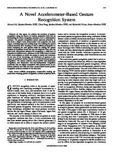
OW-POWER high-performance small-size MEMS accelerometer plays a critical role in the advancement of emerging medical motion sensing technologies such as sensing of cardiac wall motion for rate-responsive pacemakers [1], surface motion of organs for robot-assisted surgery [2], and human body motion for activity monitoring and analysis [3]. Fig. 1 shows how the MEMS accelerometer is utilized together with the pacemaker in the cardiac wall motion sensing application. In this implantable motion sensing application, it is extremely important for the accelerometer to achieve both low power consumption and small size without sacrificing its performance and reliability. The operation of a micro-accelerometer based on capacitive MEMS sensors has the advantages of low power consumption and low-cost manufacturing, and is highly compatible with micro-electronics. The readout of a capacitive sensor involves the conversion of capacitance or its changes to an electrical signal such as voltage. A number of ΔΣ capacitive accelerometers [4-7] have been demonstrated as they benefit from direct data conversion and high Manuscript received April 1, 2010. This work was supported by Physical Logic – Bio Research Pte. Ltd. O. D. Bernal was with the Integrated Circuits and Systems Laboratory, Institute of Microelectronics, A*STAR (Agency of Science, Technology and Research), Singapore. He is now with the Department of Electronics, University of Toulouse INP-LOSE, France. K. Choe was with the Integrated Circuits and Systems Laboratory, Institute of Microelectronics, A*STAR (Agency of Science, Technology and Research), Singapore. He is now with the Electrical Engineering Department, Yale University, Connecticut, USA. P. K. Gopalakrishnan was with the Integrated Circuits and Systems Laboratory, Institute of Microelectronics, A*STAR (Agency of Science, Technology and Research), Singapore. He is now with RV-VLSI Design Center, Bangalore, India. H-Y. Cheng, K. R. Krishna and M. Je are with the Integrated Circuits and Systems Laboratory, Institute of Microelectronics, A*STAR (Agency of Science), Technology and Research, Singapore (phone: 65-6770-5507; fax: 65-6778-0136; e-mail:
[email protected]). D. Nuttman and N. Axelrod are with Physical Logic, Bnei Brak, Israel; a medical & military MEMS-based accelerometers company (phone: +972-35708188; e-mail:
[email protected])
978-1-4244-4124-2/10/$25.00 ©2010 IEEE
MEMS Acceleration Sensor
3-D Integration of Accelerometer
Fig. 1. The use of a MEMS accelerometer together with a pacemaker in cardiac wall motion sensing application.
linearity. Nevertheless, they do not provide the best possible power efficiency for high resolution applications [8] mainly due to wideband noise aliasing and mass residual motion [6]. Further, the electro-mechanical feedback loop used in ΔΣ accelerometers requires high enough supply voltage to generate electrostatic forces capable of balancing the forces induced by large accelerations on the proof mass. This paper presents a continuous-time open-loop capacitive accelerometer, which is known to provide an optimum trade-off between power and resolution [8]. New reset and common-mode feedback (CMFB) circuit techniques based on the non-unity-gain feedback configuration are introduced to reduce further down its power consumption without compromising either the dynamic range or the stability of the analog processing chain. II. ARCHITECTURE AND NEW CIRCUIT TECHNIQUE A. Accelerometer ASIC Fig. 2 shows the architecture of the implemented fully differential transcapacitance amplifier readout scheme with the capacitive MEMS sensor. The differential MEMS sensor can be represented by a full-bridge configuration of four sense capacitors. Each sense capacitor is composed of fixed component, CS±, and a variable portion, ΔCS±, which varies proportionally to the acceleration. To readout the capacitance changes, a capacitance-to-voltage converter (CVC) is employed which can perform the signal conversion and front-end amplification. Note that the MOS-bipolar pseudoresistors are used to define the DC bias point at the
190
MEMS
CV Converter
VDRV
Reset switches
ϕrst
ϕ ϕ
Pseudoresistor
Cp
Cs-
Cs-
Cs+ Cp Rp
Power = 35μW, fchop = 10kHz NEA = 120μg/√Hz, DR > 78.5dB (400Hz BW)
High-Resolution (HR) mode:
Power = 170μW, fchop = 50kHz NEA = 45μg/√Hz, DR > 87dB (400Hz BW)
Demodulator
VGA
LPF
Variable gain: x1 to x32
VCM
Rp
Cs+
Low-Power (LP) mode:
Cint
ϕrst ϕ rst
ϕ
CMFB
Cint
Cut-off frequency: 400Hz (adjustable)
ϕ
VOUT+
ϕ ϕ
VOUT-
VCM
VCM
ϕ rst ϕ ϕ VDRV
1/fchop
ϕ
ϕ rst
ϕ
VCMFB
Fig. 2. Accelerometer architecture including MEMS sensor, CVC, demodulator, VGA and LPF.
high impedance input nodes of CVC. Four MOS transistors are connected in series to reduce the nonlinearity induced by these voltage-dependent impedance devices when the CVC output voltage swing is large. In order to reduce the offset and the flicker noise of the CVC, chopper stabilization is implemented by driving the MEMS sensor with two antiphasic clock signals for modulation and demodulating the output of the CVC with the same clock [9]. A resistive voltage gain amplifier (VGA) follows the demodulator switches to provide additional gain and system flexibility. The last stage, a 400Hz low pass filter (LPF), limits the bandwidth of both output signal and noise of the accelerometer. Note that the accelerometer ASIC can operate across different operation modes (sleep, low-power and high-resolution modes) to provide an optimized sensing solution corresponding to the user’s real-time request. B. Front-End Amplifier and New Circuit Design The change in the MEMS capacitance is in the range of fF and for this high-resolution sensing, the gain of the front-end amplifier (FEA) needs to be as high as possible to achieve a large signal-to-noise ratio (SNR) by minimizing the noise contributions from later stages in the processing chain. For low-voltage applications, a class AB output stage can be employed to achieve rail-to-rail output characteristic with minimum power consumption [10]. Consequently, in the CVC, a two-stage fully differential folded-cascode operational amplifier (OPA) is adopted with a class AB output stage as shown in Fig. 3. In the same way, such architecture is necessary when a resistive VGA structure is chosen. The large open-loop gain provided by the two stages of the OPA helps to minimize nonlinearity and gain error. However, the two-stage OPA has to consume a large additional power in the 2nd stage, because the stability requirement must be met in the unity-gain feedback condition which holds during the reset operation of the CVC. Note also that the CMFB circuit
VDD VB6 VB5 MF
Vout+
MF
VB4 MD
CC CC
MD MC
CC
MC VB3
ME
Vout-
CC
ME
Vin+
VinVB2
VCMFB
VB1 MB MA
M A MB
Fig. 3. Operational amplifier circuit diagram used for the CVC and VGA.
faces the same power overhead problem in order to ensure the stability. Considering the normal operation of CVC (Fig. 2), the closed-loop gain (CLG) is given by (2Cs+Cp+Cint)/Cint, where Cs is the MEMS sense capacitance, Cp the total parasitic capacitance at CVC input nodes, and Cint the integration capacitance of CVC, and thus larger than unity (larger than 10 in this design). Therefore, power consumption can be significantly reduced in the 2nd stage of the CVC by relaxing the stability requirement, if the unity-gain feedback configuration can be avoided during the reset operation. The new reset scheme shown in Fig. 4 uses two switches Ms1 and Ms2 in the feedback path to reset Cint, instead of a single switch used in conventional schemes. The CLG during the reset operation can thus be set by the ratio of their sizes – ((W/L)Ms1+(W/L)Ms2)/(W/L)Ms2. Assuming a weak-inversion design, the 2nd stage power consumption can
191
CMFB Loop βreset =
Bias generation to minimize passive power and area consumption
β CMFB =
1 n+1
1 (W/L)Ms2 = 1+ GCL,reset (W/L)Ms1
Reset Loop
Fig. 5. Chip micrograph (technology: 0.13 3µm CMOS with MIM capacitor option).
Power reduction while achieving the same stability: ⎛ (W/L)Ms2 ⎞ ⎟ from the 2nd stage of the main amplifier × ⎜⎜ 1 + (W/L)Ms1 ⎟⎠ ⎝ ×
1 from the CMFB amplifier n+1
Fig. 4. Circuit Diagram of the proposed non-unityy-gain CMFB and reset scheme.
be directly scaled down by this CLG, whichh is set to 5 in this work. While achieving the same 70o phasee margin, the 2nd stage current consumption can be reducedd from 100µA to 20µA. The differential input pair in the 1st stage is biased with 16µA to achieve 4) may not ensure a proper operation of the CMFB under worst-case process variations or largee common-mode disturbances. Therefore, to improve furrther the CMFB stability, a non-unity-gain CMFB is proposed here. The CMFB CLG, βCMFB, is set by the resistancce ratio n+1 (Fig. 4). By adding a simple bias generationn circuitry, both passive power and silicon area, which are consumed by the common-mode sensing resistors, can bee advantageously reduced.
consuming 120µW, 15µW and 35µ µW respectively in highresolution mode. In sleep mod de, the overall power consumption is less than 1µW. A maximal m THD of 0.25% is observed for a 2.4Vpp output voltaage (electrical test only). The noise spectrum was measured both in low-power (LP) and high-resolution (HR) modes as shown s in Fig. 6. Without the MEMS, in low-pow wer mode, with a 10kHz chopping clock, the input noise equivalent acceleration g/√Hz is achieved with density is 140µg/√Hz, while 57µg 50kHz chopping in high-resolution mode. With the MEMS, the total noise spectral density is 12 20µg/√Hz and 45µg/√Hz in low-power and high-resolution modes, m respectively. Note that larger noise density is observed in ASIC stand-alone test due to the larger parasitic capacitance Cp contributed from the package and test board. uit is tested for the bias The accelerometer readout circu instability for 12 hours with and without w the MEMS in a laboratory environment. Fig. 7 sh hows the measured bias instability of the system through thee Allan variance analysis [11]. The measured bias instabilitty is around 31µg. The accelerometer output voltage meaasured as a function of acceleration is shown in Fig. 8. The T accelerometer output voltage increases linearly up to 25g with the sensitivity of 18mV/g. Note that ±25g operation n range is limited by the shaker used. Considering a 400Hz bandwidth b and a full scale
III. RESULTS AND DISCUSSIO ON The accelerometer ASIC (Fig. 2) was fabbricated in a 1.5V 0.13µm CMOS technology with MIM ccapacitors. A die photo of the full accelerometer readout cirrcuit is shown in Fig. 5. The chip operation is controlled thhrough the serial peripheral interface (SPI). All the requirred passive components were integrated and the total active area is 1×0.6mm2. The ASIC is combined with a 1.8fF/g MEMS accelerometer in the same DIP package bbut it can also be electrically characterized without the M MEMS sensor by mimicking the sensor behavior through a capacitive VGA configuration. Based on the proposed nonn-unity-gain reset and CMFB schemes, in low-power mode, the CVC, VGA, and LPF consume 22.5µW, 4µW andd 8.5µW, while
192
Fig. 6. Measured spectral density of the noise n equivalent acceleration from the accelerometer ASIC with and without the MEMS in lowpower and high-resolution modes.
Allan Deviation, σy [ g ]
10m
TABLE I COMPARISON WITH OTHER ACCELEROMETER WORKS
ASIC only
Parameter Supply voltage (V) Power consumption (W/axis) Full scale (g) Noise density (µg/√Hz) Dynamic Range (dB)
1m ASIC & MEMS
100u
Bias instability = 31μg
10u 10m
100m
1
10
100
1k
10k
* **
100k
τ [ sec ] Fig. 7. Allan deviation plot of the accelerometer ASIC with and without the MEMS.
Output Voltage [ V ]
[2] 0.4
[3] 0.3
[4] 0.2
0.1
[5] 0
5
10
15
20
[12]
[9]
[6]
[13]
[14]
1.5
2.4
5
5
1
3
170µ
680µ
20m
7.2m
1.5µ
3.7m
> ±25 *
±2
-
±2.3
±2
±1
45
50
30
0.8
704
6.3
> 87
60
< 82 **
101
41
76
Full scale measurement was limited to ±25g due to the shaker. Maximum possible dynamic range was inferred from the reported sensitivity and maximum possible full scale when a rail-to-rail output range assumed.
REFERENCES [1]
0.5
0.0
This work
25
Acceleration [ g ]
[6]
Fig. 8. The measured output voltage of the accelerometer versus acceleration. [7]
larger than ±25g, the dynamic range is larger than 78.5dB in low-power mode and 87dB in high-resolution mode. This work is favorably compared with other accelerometer works as shown in Table I by successfully achieving both the low power consumption and high performance at the same time. Note that the MEMS acceleration sensor is under re-fabrication to increase its sensitivity by ten times to obtain more useful acceleration sensing range for targeted applications. The sensing range is currently 1mg to >±25g and will become 100µg to >±2.5g with new MEMS sensors.
[9]
IV. CONCLUSION
[11]
A low-power high-resolution ASIC interfacing with a MEMS accelerometer sensor has been presented. It has been shown that to ensure lower power consumption: (1) a continuous time approach is preferred, (2) the non-unity gain closed-loop feedback mainly due to MEMS-ASIC capacitive parasitics should be taken into account during the design phase, and (3) maximizing the signal output voltage directly after the CVC stage is better. A new reset and CMFB design technique based on a non-unity-gain feedback approach has been proposed to reduce the power consumption further without stability penalty. This accelerometer ASIC achieves a resolution better than 14 bits while consuming only 170µW from a 1.5V supply voltage.
[8]
[10]
[12]
[13]
[14]
193
S.A.P. Haddad, R.P.M Houben, and W.A. Serdijn, “The Evolution of Pacemakers”, in IEEE Eng. Med. Bio. Mag., vol. 25, May/June 2006, pp. 38-48. T. Ortmaier, Motion Estimation in Beating Heart Surgery, in IEEE Trans. Biomed. Eng., vol. 52, Oct 2005, pp. 1729-1740. C.V.C Bouten, “A Triaxial Accelerometer and Portable Data Processing Unit for the Assessment of Daily Physical Activity”, in IEEE Trans. Biomed. Eng., vol. 44, Mar 1997, pp. 136-147. M. Kamarainen, M. Saukoski, M. Halonen, “A micropower differential charge-balancing switched-capacitor front-end for capacitive microaccelerometers”, Circuit Theory and Design, 2005. in Proceedings of the 2005 European Conference on, vol. 3, Sept 2005, pp. 421-424. Babak Vakili Amini, R. Abdolvand and Farrokh Ayazi, “A 4.5mA Closed- Loop __ΔΣ Micro-Gravity CMOS SOI Accelerometer”, in Dig. Tech. of International Solid-State Circuits Conference, Feb 2006, pp. 1101-1102. Haluk Kulah, Junseok Chae, Navid Yazdi, and Khalil Najafi, “Noise Analysis and Characterization of a Sigma-Delta Capacitive Microaccelerometer”, in IEEE Journal of Solid-State Circuits, vol. 41, no. 2, February 2006, pp. 352-361. N. Yazdi, H. Kulah and K. Najafi, “Precision readout circuits for capacitive microaccelerometers”, in IEEE sensors proceedings, vol.1, pp. 28-31, 2004. W. Jiangfeng, G.K. Fedder and L.R. Carley, “A low-noise low-offset capacitive sensing amplifier for a 50-μg/√Hz monolithic CMOS MEMS accelerometer”, in IEEE Journal of Solid-State Circuits, vol. 39, Issue 5, pp. 722-730, May 2004. M. Tavakoli, and R. Sarpeshkar, “An Offset-Canceling Low-Noise Lock-In Architecture for Capacitive Sensing”, in IEEE Journal of Solid-State Circuits, vol. 38, no. 2, pp. 244-253, Feb. 2003. Ron Hogervorst and John P. Tero and Ruud G. H. Eschauzier and Johan H. Huijsing, “A Compact Power-Efficient 3 V CMOS Rail-toRail Input/Output Operational Amplifier for VLSI Cell Libraries”, in IEEE Journal of Solid-State Circuits, vol. 29, no. 12, December 1994, pp. 1505-1512. IEEE Recommended Practice for Inertial Sensor Test Equipment Instrumentation, Data Acquisition, and Analysis, IEEE Std 15542005. Matti Paavola and Mika Kmrinen and Jere A. M. Jrvinen and Mikko Saukoski and Mika Laiho and Kari A. I. Halonen, “A Micropower Interface ASIC for a Capacitive 3-Axis Micro-Accelerometer”, in IEEE Journal of Solid-State Circuits, 2007, vol. 42, pp 2651-2665. Mika Kmrinen and Matti Paavola and Mikko Saukoski and Erkka Laulainen and Lauri Koskinen and Marko Kosunen and Kari Halonen, “A 1.5µW 1V 2nd-Order ΔΣ Sensor Front-End with Signal Boosting and Offset Compensation for a Capacitive 3-Axis MicroAccelerometer”, in Dig. Tech. of IEEE International Solid-State Circuits Conference Feb 2008, pp. 578-580. Dongning Zhao and M. Faisal Zaman and Farrokh Ayazi, “A Chopper- Stabilized Lateral-BJT-Input Interface in 0.6μm CMOS for Capacitive Accelerometers”, in Dig. Tech. of IEEE International Solid-State Circuits Conference Feb 2008, vol. 32, Mems & Sensor, pp. 584-586.