A Microcontroller Based Gate Drive Circuit for Three-Phase Line Commutated SCR. Inverter. Tapan Kumar Chakraborty*, Shahruk Osman** and Nadia Binte ...
A Microcontroller Based Gate Drive Circuit for Three-Phase Line Commutated SCR Inverter Tapan Kumar Chakraborty*, Shahruk Osman** and Nadia Binte Asif***
ABSTRACT
this paper concerns the design and implementation of a simple microcontroller based gate-pulse generating circuit for three-phase line commutated SCR inverter connected to a synchronous motor. The control scheme is consisting of terminal voltage sensor, comparator, AVR microcontroller, reference dc voltage source, and pulse amplifier and isolating circuit. The gate pulses for the six SCRs of the inverter are generated by the microcontroller from the comparator output. It is found that the firing angle can be controlled satisfactorily from 90o to 180o by changing the reference dc voltage. The firing angle, once adjusted, remains constant irrespective of the changes in machine terminal ac voltage and frequency. Microcontroller; line-commutation; SCR inverter, Constant firing angle, variable voltage and frequency. Keywords:
INTRODUCTION Nowadays, synchronous motor drives fed by thruster inverters are widely used in industry for precise and smooth control of speed with long-term stability and good transient performance as that of a dc motors [15]. Besides it is possible to use the silicon-controlled-rectifier (SCR) based inverter for the adjustability of power factor and the constancy in speed for a given frequency. Conventional dc motor drives are used as motor drives for many cases. However, due to several drawbacks such as, mechanical commentator needs regular maintenance, power/weight ratio reduces due to the additional weight of commentator, brush and commentator wear occurs due to friction and sparking, the commentator construction increases the cost of the dc motor drive, and unsuitable to operate in explosive and dusty environments; it is not advisable to use dc motor drives in many industrial applications. Modern variable drives uses synchronous motor fed from current source inverters which uses the machine EMF for commutation, thus removing the usage of costly commutating equipment and complexity. The power circuit and firing control circuit configuration of the inverter are very simple [6] in structure. *Professor, Presidency University, Bangladesh, **Asst. Prof, Presidency University, Bangladesh, Lecturer, Presidency University, Bangladesh.
There has been some research works performed on the line commutated inverter fed synchronous motor [7-10]. Most of the research works highlighted the use of speed sensor to generate triggering pulses for the SCRs of the inverter. Such hardware for the system based on rotor position might impose problems on both the machine as well as system design. In this paper, attention is paid on the microcontroller based gate drive circuit for three phase SCR inverter using terminal voltage sensor. SYSTEM DESCRIPTION AND OPERATION Fig. 1 shows the block diagram the microcontroller based gate drive circuit for three-phase line commutated SCR inverter. The system comprises of a three-phase autotransformer, an uncontrolled threephase bridge rectifier, a dc link inductor, a three-phase line commutated inverter, microcontroller gate drive circuit, firing angle control input, LCD interface and a comparator circuit. The function of the dc link inductor is to suppress the harmonics contained in the output of the bridge rectifier. The combination of the uncontrolled rectifier and dc link inductor acts as a current source for the inverter. The excitation winding of the synchronous machine is connected in series to the input of the inverter. The synchronizing signal is obtained by sensing line-to-line voltages with the help of a small step-down transformer from the synchronous machine terminals as shown in fig. 1. The secondary voltage of the transformer is compared with a dc reference signal using a 741C op-amp comparator to produce an alternating rectangular waveform of a variable pulse width. The output of the comparator ideally swings between +5 and -5 V at every zero crossing of transformer output voltage. The microcontroller is programmed to generate firing pulses for six SCRs of the inverter in proper sequence. The firing angle can be changed at any instant by incrementing or decrementing by 1° using control input buttons (increment, decrement & set). The firing angle could be observed through LCD interface.
Fig. 1. Block diagram of microcontroller based gate drive circuit for the three-phase SCR inverter.
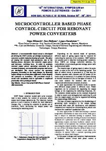
Fig. 2. Flow Chart of the Program
SOFTWARE IMPLEMENTATION Microcontroller unit accepts input from comparator circuit to sense the terminal voltage change. The given logic in microcontroller then calculates the new firing angle for six different channels. Microcontroller board with 2-line LCD display is used for showing the current ADC value, as well as the
corresponding firing angle. Embedded C language is used for programming of AVR microcontroller. The algorithm for implementation of this scheme is developed using embedded C language. The compilation of executable software code is achieved using WinAVR, a development tool for the AT mega AVR processor, hosted on Windows. The compiled executable code in the form of hex file can be downloaded in the microcontroller chip. This burning of the chip embeds the necessary instructions in the chip memory. Figure 2 shows the flow chart of the microcontroller program. The program starts by initializing the timer, ADC, I/O etc. The comparator output fed into the microcontroller is used to detect zero -crossing mo ments of the phase voltage. During the lo w-h igh transition of rectangular pulse fro m comparator circuit, the controller starts the timer. It stops the timer and calculates the time period during the next high -low transition. It is able to calculate the time duration for 1° firing angle and is able to generate firing pulses according to input firing angle instruction through ADC. In total 6 firing pulses of duration 0.1ms are generated at the outputs of the controller with an interval of 60°.
RESULTS AND DISCUSSIONS The secondary voltage of the step down transformer connected to the terminals of the synchronous motor is compared with zero dc reference voltage using an op-amp based comparator to produce an alternating rectangular waveform of a variable pulse width proportional to the system frequency. The output of the comparator ideally swings between +5 and -5 V at every zero crossing of transformer output voltage. It is used a CLK input to the microcontroller to calculate the delay time to generate firing pulses for six SCRs of the inverter in proper sequence. The firing angle can be changed at any instant by incrementing or decrementing by 1° using control input buttons. The firing angle could be observed through LCD interface. Figure 3 shows the simulation result between line to line voltage and line to neutral voltages. It can be observed that the phase difference between line to line voltages is 120° whereas the phase difference between line-line and line-neutral is 30°. Therefore, the triggering pulses for six SCRs of the three phase
inverter are generated by the control circuit in proper sequence with a reference angle starting from 30°+90°=120° and separation of 60° between the firing pulses.
Fig. 4 : Phase voltage Van and gating pulses for T1, T2 a nd T3
Fig. 3. Relationship between line-line and line-neutral voltage
Fig. 5. Phase voltage Van and gating pulses for T 4, T 5 and T 6
Figure 4 shows the simulat ion result of generation of gating pulse T1, T2 and T3 at the microcontroller output. It can T1 starts at 30°+90°=120° instant and T2 is separated by 60° fro m T1 and T3 separated by 60° fro m T2. Fig. 5 shows the simulat ion result of generation of gating pulses for T4,T5 and T6 be observed that the reference gating
pulse at the microcontroller output. T4 is separated by 60° fro m T3; T5 is separated by 60° fro m T4 and T6 separated by 60° from T5. Figure 6 shows the experimental setup of the microcontroller based system. CONCLUSION Design and simu lation of a simp le microcontroller based gate-drive circuit for three-phase line commutated SCR inverter connected to a synchronous motor has been presented. The microcontroller generates gate pulses for the six SCRs of the inverter fro m the co mparator output in proper sequence. It is found that the firing angle can be controlled satisfactorily fro m 90o to 180o by changing the reference dc voltage. The firing angle, once adjusted, remains constant irrespective of the changes in machine terminal ac voltage and frequency. 1.
REFERENCES
S. Sengupta, S. N. Bhadra and A. K. Chattopadhyay, “ An Inverter Fed Self -Controlled Commutatatorless Series Motor with the Field Winding in the DC Link”, IEEE Transactions on Industry Applications, Vol.33, No.4, August 1997. [2] R. Arulmozhiyal, and K. Baskaran, "Space vector pulse width modulation based speed control of induction motor using fuzzy PI controller, "International Journal of Computer and Electrical Engineering, vol. 1, no. 1, pp. 98-103, April 2009. [3] A. Maamoun, A. Soliman, and A. M. Kheirelden, "Space-vector PWM inverter feeding a small induction motor," in Proc. IEEE International Conference on Mechatronics, Komamoto, Japan, pp. 1 -4, May 2007. [4] A. B. Chattopadhyay, S. T homas and R. Chatterjee, “ Analysis of Steady State Analysis of a Current Source Inverter Fed Synchronous Motor Drive System with Damper Windings Included”, Trends in Applied Sciences Research, Vol.9, No.6, pp.992 -1005, 2011. [5] M. N. Uddin, and R. S. Rebeiro, “Online Efficiency Optimization of a Fuzzy-Logic Controller-based IPM Synchronous Motor”, IEEE T ransaction on Industry Applications, Vol.47, No.2, April 2011. [6] T. K. Chakraborty, B. Singh, and S. P. Gupta, “ A Microprocessor-based Firing Control Scheme for Three-Phase Thyristor Power Converter”, Journal of Microcomputer Applications, Vol.13, pp.361-369, 1990. [7] T. K. Chakraborty, “Microprocessor controlled commutatorless DC series motor drive”, M. Sc. Engg Thesis, Department of Electr ical Engineering, University of Roorkee, 1988. [8] F.C. Brockhurst, "Performance Equations for D.C Commutatorless Motors using Salient Pole Synchronous Type Machines", IEEE T ransaction on Industry Applications, Vol. IA - 16, No. 3, pp. 362 - 371, May / June 1980. [9] H. Naitoh and F. Harashima, "Effects of magnetic saturation on the performance of thyristor commutatorless motor”, IEEE Transa ction on Industry Applications, Vol. IA- 18, No. 1, pp. 213-218, May/June, 1982. [10] H. Natio, K. Iwamoto and F. Harashima, "Dynamic Characteristics and Instability problems of Triggering Lead Angle Controlled Commutatiorless Motors", Electrical Engineering in Japan Vol.102, No.4, pp. 81 - 90, July/August, 1982. [1]