52.5
A Model-driven Design Environment for Embedded Systems E. Riccobene
P. Scandurra
A. Rosti and S. Bocchio
University of Milano DTI, Crema, Italy
University of Catania DMI, Catania, Italy
STMicroelectronics Lab R&I, Agrate Brianza, Italy
[email protected]
[email protected]
{alberto.rosti,sara.bocchio}
@st.com ABSTRACT This paper presents a prototype environment for HW/SW co–design of embedded systems based on the Unified Modeling Language (UML) and SystemC. The environment supports a model-driven SoC design methodology which provides a graphical high-level representation of hardware and software components, and allows either C/C++/SystemC code generation from models and a reverse engineering process from code to graphical UML models. Categories and Subject Descriptors: J.6 [Computer Applications]: Computer-aided engineering – computer-aided design (CAD) General Terms: Design, Languages, Documentation. Keywords: HW/SW Co-design, UML, MDA, SystemC.
1.
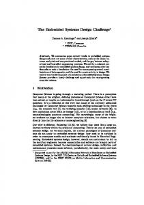
Figure 1: Tool architecture
In this paper, we present a prototype HW-SW co-design environment that we have been developing to support this model-driven SoC design flow. It works as front-end for consolidated lower level co-design tools, and was primarily intended to assist the designer across the refinement steps in the UML modeling activity, from a high-level functional model of the system down to the RTL level. Our framework allows to use the UML profile to provide a graphical entry for SystemC-based designs by UML diagrams, to generate SystemC code from models, and to perform reverse engineering from code to UML models. This paper is organized as follows. Section 2 presents the environment architecture and its components features. Section 3 and 4 contain design examples. Section 5 lists some related work. Section 6 draws some conclusions and envisages future possible enhancements.
INTRODUCTION
Conventional system level design flows for System on Chip (SoC) usually start by writing the system specification and developing a functional executable model. The system is refined through a set of abstraction levels, towards a final implementation in hardware and software. Nowadays it is an emerging practice to develop the functional model and refine it with the C/C++/SystemC languages [25]. The hardware part of the system goes down to the RTL level for the synthesis flow, while the software part can be either simulated at high (functional or transactional) level or compiled for an Instruction Set Simulator (ISS). In our opinion a further improvement to this practice can be achieved by exploiting lightweight software modeling languages like UML [28] to describe system specifications and generate from them executable models in C/C++/SystemC. In accordance with the design principles of the OMG’s Model-driven architecture (MDA) [11], we defined a modeldriven SoC design methodology [19, 2] which involves the UML 2.0, a UML 2.0 profile for the SystemC language [25], and some other UML profiles primarily related for the SW implementations.
2.
TOOL ARCHITECTURE
Figure 1 shows the tool architecture. Components visualized inside dashed lines are still under development. The tool consists of two major parts: a development kit (DK) with design and development components, and a runtime environment (RE) represented by the standard SystemC execution engine. The DK consists of a UML 2.0 modeler supporting the UML profile for SystemC [18], translators for the forward/reverse engineering to/from C/C++/SystemC, and an abstraction/refinement evaluator to guarantee traceability and correctness along the refinement process from the high-level abstract description to the final implementation. This last component is under development.
Permission to make digital or hard copies of all or part of this work for personal or classroom use is granted without fee provided that copies are not made or distributed for profit or commercial advantage and that copies bear this notice and the full citation on the first page. To copy otherwise, to republish, to post on servers or to redistribute to lists, requires prior specific permission and/or a fee. DAC 2006, July 24–28, 2006, San Francisco, California, USA. Copyright 2006 ACM 1-59593-381-6/06/0007 ...$5.00.
915
2.1
The Modeler
identified depending on the degree of completeness of the PIM and of the resulting PSM [12]: skeleton generation, partial generation, and full generation. Skeleton generation has been adopted by most tools, and deals only with the static structure of the system (classes with attributes and relations). Partial generation takes a more complete specification as input. Behavior may be modelled by state machines, sequence diagrams, activity diagrams, etc. However, these diagrams are most of the time incomplete at PIM level. The result code needs further refinement, even if it already integrates some significant pieces of behavior. Full generation tools introduce at PIM level a new action language, conforming to an action semantics. The Action Semantics proposal for the UML [1, 28], for example, defines only an action metamodel (abstract syntax) to allow an easy mapping of classical languages such as Java, C++ or SDL. There are several examples of such approach: iUML [6], Projtech BridgePoint [16], Kabira Object Switch [8], or Telelogic Tau architect/developer [26]. We followed a full generation approach; we adopted C/C++/SystemC as action languages at PSM level, so that the source code is fully generated, even if we did not adopt any action language at PIM level. The EA supports forward/reverse engineering to/from C++. We added to the EA the capability of generating complete SystemC code from UML models for both structural and behavioral views. To this end, the EA provides an automation and scripting interface for the customization of its user interface and of the templates used to generate code from UML. It is based on the Windows OLE Automation (ActiveX) technology. Therefore all development environments capable of generating ActiveX COM clients are able to connect to the EA automation interface, and this involves scripting clients like Microsoft Visual Basic 6.0. Alternatively, the XMI [30] import/export facility can be exploited to extract the model information required to generate code for a target language. We developed an EA add-in in Visual Basic 6.0 which exploits the added semantics in the profile definition to generate SystemC code from input models written in the SystemC UML profile. This application can be invoked from the main menu selecting Tools | SystemC (see Figure 2). It is possible to generate code from the whole model, at package level or even for single diagrams. Starting from the selected element in the EA project view browser (project, package or class diagram) the code generation analyzes the underlying hierarchy of views generating the corresponding C/C++ or SystemC code. The code generator traverses all class diagrams and for every encountered class it produces a C++ header file (.h); this happens both for the definition of SystemC classes (modules, channels and interfaces) and for simple C++ classes, allowing a mixed design style. Classes contain fields and methods, for each method it is possible to describe its behavior either as an inline code description or as a state machine diagram. Special state machine diagrams, called SC Process State Machines, are used to implement the behavior of the SystemC processes, i.e. of methods declared to be reactive processes running concurrently within modules. Each state machine therefore contributes to the generation and enrichment of a single body file (.cpp) which contains the implementation code of all methods of a class or module or channel. The internal structure of composite modules, especially the one of the
The modeler is built on top of Enterprise Architect (EA), version 4.5, a commercial UML visual modeling tool by Sparx Systems [3]. Among all the tools on the market this one seems to be most suitable for our purposes. EA supports UML 2.0 and the UML extension mechanism. It has stateof-the-art development including XMI import/export [30] to allow model interchange between tools, and forward/reverse engineering in the C++ programming language. There is however no reason to use other tools supporting UML 2.0 and the standard extension mechanism of UML profiles. Fig. 2 shows a screenshot of EA. The SystemC data types and predefined channels, interfaces, and ports are modelled with the core stereotypes, and are available in the Project View with the name SystemC Layer1. Stereotypes for the SystemC building constructs (modules, interfaces, ports and channels) are available to be used in various UML structural diagrams such as UML class diagrams and composite structure diagrams to represent hierarchical structures and communication blocks. Behavior is modelled by the use of special state and action stereotypes which lead to a variation of the UML state machine diagram, the SC Process State Machines. This formalism has been included in the profile to model the control flow and the reactive behavior of SystemC processes (methods and threads) within modules. A finite number of abstract behavior patterns of state machines [17] have been identified.
2.2
The Translators
The Code Generation Facility. Driving the design of code is one of the key ideas of the OMG’s Model Driven Architecture [11]. Models are used to build programs by model transformations. A platform-independent model (PIM) is created in UML without specifying technology-dependent details. The PIM can be mapped to a platform-specific model (PSM), which contains design and implementation details. The PSM is then mapped to implementation in a particular coding language. The goal is to model once, and generate everywhere.
Figure 2: Generate SystemC code from EA Currently, modeling tools support code generation in a variety of ways. Three categories of code generators can be
916
Figure 4: A master from the Simple Bus
here, and some of industrial interest like the one given in the next section. The Simple Bus case study is a well-known transactional level example, designed to perform also cycleaccurate simulation1 . It is made of about 1200 lines of code that implement a high performance, abstract bus model. The complete code is available at the SystemC web site [15]. We modelled the Simple Bus entirely in a forward engineering flow. The Simple Bus design structure is modelled by the UML composite structure diagram shown in Figure 3. There are three masters as module parts with the stereotype keyword , while all the other parts – two slave memories, a bus connecting masters and slaves, an arbiter to select a request to serve, and a clock generator – appear with the stereotype keyword as they expose interfaces. Figure 4 shows the module definition for a blocking master. It requires the interface simple bus blocking if.
Figure 3: The Simple Bus Structure
topmost level module (which represents the structure of the overall system), is captured by UML composite structure diagrams; from these diagrams several UML object diagrams can be created to describe different configuration scenarios. The composite structure diagrams and object diagrams are used to derive the module constructors in the header files. For the SW part, we are working on the C code engineering and on how to support the specification of multiple tasks and their mapping on abstract RTOSs models by including precise modeling primitives directly at UML level.
The Reverse Engineering component. This component
4. THE OCCN CASE STUDY
is made of three parts: a parser, a data structure and a XMI writer. We developed a parser for C/C++/SystemC using the JavaCC tool [7]. The component accepts SystemC code which is translated into constructs of the UML profile for SystemC, C++ code which is translated to UML classes (including the behavioral description) and C which is translated into a UML object oriented-like model (C in our vision is used to describe pure embedded software parts). The internal data structure of our reverse engineering engine captures the main structures of the C/C++/SystemC model and their relations. The XMI writer finally produces a UML model that can be imported in the EA tool. The reverse engineering facility allows us to import existing models into our environment and to achieve rapidly a high number of design cases. It is also indispensable to allow round trip engineering, that is the synchronized cooperation with code generation (forward engineering) to complete the description of a model working on both the UML model and the code. It is also useful in practice as a tool to inspect the structure of a source code graphically. This reverse engineering tool is used, in fact, by our designer community mainly for the analysis of the application code’s structure. Starting from a bunch of source code header files, which are delivered from designer group A to designer group B, it is possible, from group B, to obtain immediately a graphical representation of the significative design changes introduced at code level including structure, relations, variables, functions, etc.
3.
The OCCN project [14] focuses on modeling complex onchip communication networks by providing a highly-parameterized and configurable SystemC library. This library is made of about 14.000 lines of code and implements an abstract communication pattern for connecting multiple processing elements and storage elements on a single chip. OCCN-based models have already been used by Academia and Industry. The generic features of the OCCN modeling approach involve multiple abstraction levels (from functional level to RTL level), separation of communication and computation, and communication layering. This test case contains a mixture of SystemC constructs and C++ classes; the situation is also complicated by complex inheritances and by the fact that almost all the classes are templates. The OCCN design has been imported automatically from the C++/SystemC code into the EA-based modeler exploiting the reverse engineering facility, then it was refined using the modeling constructs of the SystemC UML profile. We are using this example to test the reverse engineering flow.
5. RELATED WORK The possibility to use UML 1.x for system design [5] started since 1999, but the general opinion at that time was that UML was not mature enough as a system design language. Nevertheless significant industrial experiences using UML in a system design process soon started leading to the first results in design methodology, such as the one in [27] that
THE SIMPLE BUS DESIGN
To test the expressive power of our profile in representing a variety of architectural and behavioral aspects, we have developed several different case studies, some taken from the SystemC distribution like the Simple Bus design described
1 Transactional models are used for functional modeling of the communication enhanced with actual timing information. Communication is modelled by channels, through interfaces which encapsulate low-level details.
917
was applied to an internal project for the development of a OFDM Wireless LAN chipset. In this project SystemC was used to provide executable models. Later more integrated design methodologies were developed. In [10], a UML profile for a platform-based approach to embedded software development is presented. It includes stereotypes to represent platform services and resources that can be assembled together. The authors also present a design methodology supported by a design environment, called Metropolis, where a set of UML diagrams (use cases, classes, state machines, activity and sequence diagrams) can be used to capture the functionality and then refine it by adding models of computation. Another approach to the unification of UML and SoC design is the HASoC (Hardware and Software Objects on Chip) [4] methodology. It is based on the UML-RT profile [21] and on the RUP process [9]. The design process starts with an uncommitted model and after a committed model is derived by partitioning the system into software and hardware, and then mapped onto a system platform. From these models a SystemC skeleton code can be also generated, but to provide a finer degree of behavioral validation, detailed C++ code must be added by hand to the skeleton code. All the works mentioned above could greatly benefit from the use of new constructs available in the UML 2.0 standardization. Currently, the UML with the enhancements of the new standardization UML 2.0 and its profile mechanism is receiving significant interest as standard approach to defining family of languages targeted to specific application domains and levels of abstraction. This is confirmed by several current standardization activities controlled by the OMG such as: the SysML proposal [24], which extends UML towards the System Engineering domain; the recent MARTE initiative [22], a new UML profile for modelling and analysis of Embedded Real-time Systems, in addition to the existing UML profile for Schedulability, Performance and Time [23]; and the UML for SoC Forum (USoC) in Japan [29] founded by Fujitsu, IBM/Rational, and CATS to define a UML extension for SoC design. SysML [24] is a conservative extension of UML 2.0 for a domain- neutral representation (i.e. a PIM model as in MDA [11]) of system engineering applications. It can be involved at the beginning of the design process, in place of the UML, for the requirements, analysis, and functional design workflows. So it is in agreement with our UML profile for SystemC, which can be thought (and effectively made) a customization of SysML rather than UML. The standardization proposal [29] by Fujitsu, in collaboration with IBM and NEC, has evident similarities with our approach, like the choice of SystemC as a target implementation language. Their profile, however, does not provide building blocks for behavior modeling. Some other proposals exist about extensions of UML towards C/C++/SystemC. However, they do not not rely on UML 2.0 and on a UML profile definition. Moreover, in all the proposals we have seen, no code generation, except in [13], from behavioral diagrams is considered.
6.
level HW/SW co-design frameworks (these last would be used therefore for the final exploration and synthesis only). To foster our methodology in a systematic and seamless manner, we are developing [20] a new design process UPSoC (Unified Process for SoC)to assist the designer across the UML modeling activity from a high-level functional model of the system down to a RTL model. We are still exploring the possibility to implement MDAstyle transformations (only recently supported by the version 5.0 of EA) according to the levels of abstraction of the UPSoC process (functional, transactional, behavioral, BCA, and RTL). We are defining a refinement methodology with precise abstraction/refinement rules for this purpose.
7.
REFERENCES
[1] OMG, UML Specification, Document ad/03-03-09, version 1.5. [2] S. Bocchio, E. Riccobene, A. Rosti, and P. Scandurra. A SoC design flow based on UML 2.0 and SystemC. In International DAC Workshop UML-SoC’05, June 2005, Anaheim, CA. [3] The Enterprise Architect tool: www.sparxsystems.com.au/. [4] M. Edwards and P. Green. UML for hardware and software object modeling. UML for Real Design of Embedded Real-time Systems, Chapter 6, 2003. [5] G.Martin. UML and VCC. White paper, Cadence Design Systems, Inc, Dec. 1999. [6] iUML, from Kennedy Carter’s website. http://www.kc.com. [7] Java Compiler Compiler. https://javacc.dev.java.net/. [8] Kabira Design Center. http://www.Kabira.com. [9] P. Kruchten. The Rational Unified Process. Addison Wesley, 1999. [10] L. Lavagno, G. Martin, A. S. Vincentelli, J. Rabaey, R. Chen, and M. Sgroi. UML and Platform based Design. UML for Real Design of Embedded Real-Time Systems, 2003. [11] OMG, Model Driven Architecture. http://www.omg.org/mda/. [12] P.-A. Muller, P. Studer, F. Fondement, and J. Bivin. Platform independent Web Application Modeling and Development with Netsilon. Journal SoSym, 2005. [13] K. Nguyen, Z. Sun, P. Thiagarajan, and W. Wong. Model-Driven SoC Design: The UML-SystemC Bridge. UML for SOC Design, Chapter 8, 2005. [14] OCCN Project: http://occn.sourceforge.net/. [15] The Open SystemC Initiative. http://www.systemc.org. [16] BridgePoint Development Suite http://www.projtech.com. [17] E. Riccobene and P. Scandurra. Modelling SystemC Process Behavior by the UML Method State Machines. In Proc. of RISE’04, volume 3475 of LNCS. Springer, 2005. [18] E. Riccobene, P. Scandurra, A. Rosti, and S. Bocchio. A UML 2.0 Profile for SystemC. ST Microelectronics Technical Report, AST-AGR-2005-3. [19] E. Riccobene, P. Scandurra, A. Rosti, and S. Bocchio. A SoC Design Methodology involving a UML 2.0 profile for SystemC. In Proc. of DATE’05, IEEE. [20] P. Scandurra. Model-driven Language Definition: metamodelling methodologies and applications. PhD thesis, University of Catania, Italy, December, 2005. [21] B. Selic. A Generic Framework for Modeling Resources with UML. In Proc. of SBCCI’03, 33:64–69, 2000, IEEE. [22] R. D. Simone et al. MARTE: A new Profile RFP for the Modelling and Analysis of Real-time Embedded Systems. In UML for SoC Design workshop at DAC’05. [23] OMG, UML-SPT profile, formal/03-09-01. [24] SysML Partners web site. http://www.sysml.org/. [25] T. Gr¨ oetker and S. Liao and G. Martin and S. Swan. System Design with SystemC. Kluwer Academic Publisher, 2002. [26] UML 2.0 Action Semantics and Telelogic TAU/Architect and TAU/Developer Action Language. White paper, Telelogic, 2004. [27] T. Moore et al. A Design Methodology for the Development of a Complex System-On-Chip using UML and Executable System Models. In Proc. of FDL, 2002. [28] OMG, UML 2.0 Superstructure, ptc/04-10-02. [29] Fujitsu Limited, IBM, NEC. A UML Extension Profile for SoC. Draft RFC to OMG, 2005-01-01. [30] OMG, XML Metadata Interchange (XMI) Specification, v1.2.
CONCLUSIONS AND FUTURE WORK
Using SystemC to link the system level SoC design flow to the consolidated VLSI design flow is a well known issue. What is innovative is the idea to rely on low-cost customized UML visual modeling tools as front-ends of lower
918