A Modified Closed Loop V/F Controlled Induction Motor Drive. C.U. Ogbuka, M.Eng. and M.U. Agu, Ph.D. Department of Electrical Engineering, University of Nigeria, Nsukka, Enugu State. E-mail:
[email protected] [email protected]
ABSTRACT A modified approach, involving the addition of a low frequency boost voltage, is developed and adopted as an enhancement to the conventional closed loop
v speed control of a three-phase f
squirrel cage induction motor modeled in the stationary qd reference frame using six-step voltage source inverter waveform. The results obtained show a superior performance in the two basic mechanical characteristics: motor speed and electromechanical torque. The performance of this proposed scheme is presented in MATLAB/SIMULINK®. (Keywords: induction motor, stationary reference frame, volts/hertz v/f control, torque and speed)
INTRODUCTION Induction machines are some of the most frequently used in industry because of their robustness, reliability, low cost, high efficiency and good self-starting capability [1, 2, 3, 4]. The induction motor, particularly with a squirrel cage rotor, is the most widely used source of mechanical power fed from an AC power system. Its low sensitivity to disturbances during operation make the squirrel cage motor the first choice when selecting a motor for a particular application [5]. In spite of this popularity, the induction motor has two inherent limitations: (1) the standard motor is not a true constant-speed machine, its full-load slip varies from less than 1% (in highhorse power motors) to more than 5% (in fractional-horsepower motors) and (2) It is not, inherently, capable of providing variable speed operations [6, 7].
The Pacific Journal of Science and Technology http://www.akamaiuniversity.us/PJST.htm
With respect to the control method, AC drives are classified into two basic categories. The first category of motors has reduced dynamic requirements. The standard drives such as pumps and fans with electric motors operating at a maximum efficiency point are the examples of this category. In the second category includes dynamically high performance industrial drives [8]. During start-up and other severe motoring operations, the induction motor draws large currents, produces voltage dips, oscillatory torques, and can even generate harmonics in the power system [9, 10, 11]. It is, therefore, important to be able to predict these phenomena. Various models have been developed and the qd or two axis model for the study of transient behaviors has been tested and proved to be very reliable and accurate [12]. This method of modeling has been applied by several authors in their analysis [13, 14]. Since it is usually more convenient to simulate an induction machine and its converters on a stationary reference frame, the model presented in this paper is on the stationary reference frame and the complete model equations for the induction motor in the stationary reference frame is derived in [15].
CLOSED LOOP V/F CONTROLLED INDUCTION MOTOR DRIVE When accuracy in speed response is a concern, closed-loop speed control can be implemented with the constant
v f
principle through the
regulation of slip speed. A PI controller is employed to regulate the slip speed of the motor to keep the motor speed at its set value.
–52– Volume 10. Number 1. May 2009 (Spring)
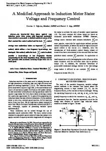
Figure 1 shows a typical closed-loop speed control scheme which uses volts/hertz and slip regulation [16].
DC Supply Constant V/F
ω
PI Speed Controller
• r
+ −
ωr
THREE PHASE VSI
Slip Limiter
• ω sl• ω e
+
Ka+(Kb/s )
ωr +
Vs
P 2
schemes utilizing PWM inverters are discussed in [17].
EVALUATION OF LOW FREQUENCY BOOST VOLTAGE The voltage relationships in the exact equivalent circuit of Figure 2 are analyzed to determine the low frequency boost voltage V0 needed to sustain motor flux even at zero frequency.
IM
Speed Sensor
Figure 1: Closed-Loop Speed Control Scheme Utilizing Volts/Hertz and Slip Regulation.
The parameter ' a ' known as the per-unit frequency, is defined as the ratio of the operating speed to the rated speed as:
a=
The major blocks consist of a DC source, a threephase inverter, and an induction motor with load. The speed loop error generates the slip speed command
ω sl•
frequency command,
ω e• .
f rated
=
ωs ω sr
(1)
I r'
Is rs
through the proportional–integral
controller and limiter. The slip is added to the speed feedback signal, ω r to generate the slip
fs
Vs
jaxls aE ar
jaxlr' jax I mm
rr' s
The slip frequency
command generates the voltage command Vs through a Volts/Hz function generator [8, 16]. A step increase in slip frequency command,
ω e• ,
produces a positive speed error and the slip speed command
ωsl∗
Figure 2: Steady State Equivalent Circuit of a Squirrel Cage Induction Motor for Variable Voltage and Frequency Control.
is set at the maximum
value. The drive accelerates at the permissible inverter current, producing the maximum available torque, until the speed error is reduced to a very small value. The drive finally settles at a slip speed for which the motor torque balances the load torque. A step decrease in slip frequency command,
http://www.akamaiuniversity.us/PJST.htm
Vs = aE ar + ( I m + I r' )(rs + jaxls ) Where I m + I r = ( '
ω e• ,
produces a negative speed error. The slip speed command is set at the maximum negative value. The drive accelerates under regenerative braking; at the maximum permissible current and the maximum available breaking torque, until the speed error is reduced to a small value. Now the operation shifts to motoring and the drive settles at the slip speed for which the motor torque equal the load torque. Several other closed-loop control The Pacific Journal of Science and Technology
From figure 2,
jE ar aE + ' ar ) xm rr + jaxlr' s
(2)
(3)
Therefore,
Vs = aE ar + (rs + jaxls )(
jE ar E + ' ar ) (4) xm rr + xlr' as
Equation 4 is programmed in MATLAB® as ' a ' varies in the range 0.1 ≤ a ≤ 1 as shown below.
–53– Volume 10. Number 1. May 2009 (Spring)
Tem = TL +
2 dω r J p dt
(6)
Where p is the operator d/dt, rs is the stator '
resistance, rr is the rotor resistance referred to '
the stator side, Lls and Llr are the stator and rotor leakage inductance respectively. Lm is the Figure 3: Look-Up Plot for Modified
v Control. f
magnetizing inductance,
TL is the load torque, P is the number of pole pairs, J is the moment
of inertia,
ωr
is the rotor electrical speed, and
V0 =13.3261V is obtained by extrapolating the
ω e is the supply synchronous speed.
straight line and determining the point of intersection at a=0. This low frequency boost voltage is utilized in the constant Volts/Hertz generator in the closed loop arrangement.
DYNAMIC PERFORMANCE UNDER REFERENCE SPEED VARIATION A closed loop
INDUCTION MACHINE MODEL IN STATIONARY REFERENCE FRAME Making reference to the induction machine model in the arbitrary reference frame and substituting ω = 0 , the induction machine model in the stationary reference frame is realized. This is called the stationary reference frame because the qd axis does not rotate and is said to be fixed in the stator. The analysis done above recognizes that in a vast majority of cases, the machine is connected in delta or wye such that the neutral current does not flow. In this case, the neutral axis voltages and currents are identically zero. The machine model in stationary reference frame for a squirrel cage induction machine is:
0 0 ⎤⎡iqs ⎤ Lm p ⎡vqs ⎤ ⎡rs + Ls p ⎢v ⎥ ⎢ 0 0 rs + Ls p Lm p ⎥⎥⎢⎢ids ⎥⎥ (5) ⎢ ds ⎥ = ⎢ ⎢ 0 ⎥ ⎢ Lm p −ωr Lm rr' + L'r p −ωr L'r ⎥⎢iqr' ⎥ ⎥⎢ ⎥ ⎢ ⎥ ⎢ ωr L'r rr' + L'r p⎦⎣idr' ⎦ Lm p ⎣ 0 ⎦ ⎣ −ωr Lm
and Lr = Llr + Lm
The electromechanical evaluated as:
'
torque
developed
The Pacific Journal of Science and Technology http://www.akamaiuniversity.us/PJST.htm
Table 1: Sample Machine Data Rated Voltage Winding Connection Rated Frequency Number of Poles Rated Speed Stator Resistance Rotor Referred Resistance Stator Reactance Rotor Referred Reactance Magnetizing Reactance Moment of Inertia
400V Star 50Hz 6 960rpm 0.4Ω 0.2Ω 1.5Ω 1.5Ω 30Ω 2.1kg.m2
The speed reference is changed from 25Hz to 50Hz at load torque TL=0 Nm. The effect on motor speed is observed in Figure 4, while the effect on electromechanical torque delivered by the motor is shown in Figure 5. A sudden jerk is noticed on the load torque at the time the sudden change in reference speed occurred.
vqs = 2Vs cos ωet , vds = − 2Vs sin ωet , '
simulated in the stationary reference frame using MATLAB/SIMULINK®. The parameters of the sample motor are shown in Table 1 below.
Effect of a Step Change in Reference Speed
Where,
Ls = Lls + Lm
v controlled induction motor is f
is
–54– Volume 10. Number 1. May 2009 (Spring)
Figure 4: Rotor Speed for Step Change in Reference Speed.
Figure 6: Speed Reversal Due to Change in Reference Speed.
Figure 5: Electromechanical Torque for Step Change in Reference Speed.
Figure 7: Electromechanical Torque Due to Change in Speed Reference.
Effect of Reversal in Speed Reference With a load torque of 0Nm, Figure 6 shows the rotor speed due to the reference speed reversal in the sequence [0 50 -50 50 0]Hz while Figure 7 shows the effect on the electromechanical torque. The speed and torque transients are, as expected, observed each time the reference speed crosses the zero point. The transient effects needs definite time to settle as can be observed in the curves.
The Pacific Journal of Science and Technology http://www.akamaiuniversity.us/PJST.htm
DYNAMIC PERFORMANCE UNDER LOAD TORQUE VARIATION Sequential changes in Load Torque at Reference Speed of 50Hz Dynamic performance is observed when load torque changes in the sequence [0 30 15 30 0] Nm at a reference speed of 50Hz. Figure 8 shows the speed changes due to the programmed sequence of load torque variation while Figure 9 shows the change in electromechanical torque due to the load torque changes.
–55– Volume 10. Number 1. May 2009 (Spring)
Figure 8: Rotor Speed for Programmed Changes in Load Torque.
Figure 10: Rotor Speed for Step Change in Load Torque from 0Nm to 50Nm at Reference Speed of 25Hz.
Figure 9: Electromechanical Torque for Programmed Changes in Load Torque.
Step change in Load Torque at a Reference Speed of 25Hz Figures 10 and 11 show the rotor speed and electromechanical torque respectively due to the load torque changes from 0 Nm to 50 Nm at a reference speed of 25Hz.
CONCLUSION The scheme presented here has successfully incorporated the estimated low frequency boost voltage to the conventional closed loop v/f control modeled in the stationary qd reference frame.
The Pacific Journal of Science and Technology http://www.akamaiuniversity.us/PJST.htm
Figure 11: Electromagnetic Torque for Step Change in Load Torque at Reference Speed of 25Hz.
The choice of the stationary reference frame is made because of its compatibility with the threephase six step inverter waveform used in place of actual inverter model. This modification is validated for the dynamic performance by subjecting it to reference speed and load torque variations. The ripple in motor speed and electromechanical torque due to sudden changes in reference speed and load torque are observed as expected.
–56– Volume 10. Number 1. May 2009 (Spring)
REFERENCES 1.
Leonhard, W. 1995. ‘‘Controlled AC Drives, A Successful Transfer from Ideas to Industrial Practice’’. CETTI 95. Brazil, pp. 1-12.
2.
Okoro, O.I. 2005. ‘‘Steady and Transient States Thermal Analysis of a 7.5KW Squirrel-cage Induction Machine at Rated-Load Operation’., IEEE Transactions on Energy Conversion. 20(4):730-736.
3.
4.
5.
Okoro, O.I. 2005. ‘‘Dynamic Modelling and Simulation of Squirrel-Cage Asynchronous Machine with Non-Linear Effects’’. Journal of ASTM International. 2(6):1-16. MacDonald, M.L. and P.C. Sen. 1979. ‘‘Control Loop Study of Induction Motor Drive Using D-Q Model’’. IEEE Transaction on Industrial Electronics and Control Instrumentation. 26(4):237-241. Ostovic, V. 1994. Computer-Aided Analysis of Electric Machines. Prentice Hall International (UK) Ltd.: London, UK.
6.
Okoro, O.I. 2004. ‘‘MATLAB Simulation of Induction Machine with Saturable Leakage and Magnetizing Inductances’’, Botswana Journal of Technology. 13(2): 20-28.
7.
Fitzgerald, A.E. 1990. Electric Machinery. 5th Edition, McGraw-Hill Inc.: New York, NY.
8.
Mulay, S.P. and M.V. Aware. 2008. ‘‘V/F Control of an Induction Machine Predicting Inverter Machine Interaction’’. International Journal of Innovation in Energy Systems and Power. 3(1):27-31.
9.
Limebeer, D.J.N. and R.G. Harley. 1981. ‘‘Subsynchronous Resonance of Single Cage Induction Motors’’. Proc. Inst. Electr. Eng., Part B. (128):33-42.
10. Landy, C.F. 1972. ‘‘The Predictions of Transient Torques Produced in Induction Motors due to Rapid Reconnection of Supply’’. Trans. S. Africa Inst. Electr. Eng. 63:178-185. 11. Pillay, P. and R.G. Harley. 1983. ‘‘Comparison of Models for Predicting Disturbances Caused by Induction Motor Starting’’. SAIEE Symposium on Power Systems Disturbances. Pretoria, South Africa. 12. Lee, R.J, P. Pillay, and R.G. Harley. 1984/1985. ‘‘D,Q Reference Frame for the Simulation of Induction Motors’’. Electric Power Systems Research. 8:15-16. 13. Jordan, H.E. 1967. ‘‘Digital Computer Analysis of Induction Machines in Dynamic Systems’’. IEEE The Pacific Journal of Science and Technology http://www.akamaiuniversity.us/PJST.htm
Transaction on Power Apparatus and System. PAS-86, (6): 722-728. 14. Chattopadhyay, A.K. 1976. ‘‘Digital Computer Simulation of an Adjustable-Speed Induction Motor Drive with a Cycloconverter-Type ThyristorCommutator in the Rotor’’. IEEE Transactions on Industrial Electronics and Control Instrumentation. IECI-23(1):86-92. 15. Ong, C.M. 1997. ‘Dynamic Simulation of Electric Machinery Using MATLAB and SIMULINK. Prentice Hall PTR: Princeton, NJ. 16. Yu, Z. and D. Figoli. 1998. ‘‘AC Induction Motor Control Using Constant V/Hz Principle and Space Vector PWM Technique with TM320C240’’. Texas Instruments: Houston, TX. 17. Bose, B.K. 1986. Power Electronics and AC Drives. Prentice-Hall, Englewood Cliffs, NJ.
ABOUT THE AUTHORS Engr. Ogbuka, Cosmas Uchenna received his B.Eng. (First Class Honors) and M.Eng. degrees in 2004 and 2008, respectively, in the Department of Electrical Engineering University of Nigeria, Nsukka where he presently works as a Lecturer/Research Student. His research interests are in Adjustable Speed Drives of Electrical Machines: (DC and AC Electric Machine Torque/Speed Control with Converters and Inverters) and Power Electronics. Engr. Prof. Agu, Marcel U. obtained his B.Sc. in Electrical Engineering in 1974 in the University of Nigeria, Nsukka. He also received his M.A.Sc. and Ph.D. in 1978 and 1982, respectively, in Power Electronics from the University of Toronto, Canada. He is a Professor of Power Electronic in the Department of Electrical Engineering University of Nigeria, Nsukka. His research interests are in, but not limited to, Power Electronic Circuits (Solid State AC/DC and DC/DC Converters, Inverter Circuits and Cycloconverter/inverter circuits), Static Electric Motor Drives (DC and AC Electric Machine Torque/Speed Control with Converters and Inverters), Analogue, digital and microprocessorbased electronic control circuits, Static Induction Heating Power Supplies for heat treatment of metals (melting, casting, forging, forming, annealing, hardening), Renewable Energy Sources (especially in the area of working with solar photo voltaic cells and panels to realize
–57– Volume 10. Number 1. May 2009 (Spring)
solar lighting, heating, battery charging and water pumping), Power System Distribution for Residential, Commercial and Industrial Areas.
SUGGESTED CITATION Ogbuka, C.U. and M.U. Agu. 2009. “A Modified Closed Loop V/F Controlled Induction Motor Drive”. Pacific Journal of Science and Technology. 10(1):52-58.
Pacific Journal of Science and Technology
The Pacific Journal of Science and Technology http://www.akamaiuniversity.us/PJST.htm
–58– Volume 10. Number 1. May 2009 (Spring)