A Modified Approach to Induction Motor Stator Voltage and Frequency Control. C.U. Ogbuka, M.Eng. and M.U. Agu, Ph.D. Department of Electrical Engineering, University of Nigeria, Nsukka, Enugu State. E-mail:
[email protected] [email protected]
inherently, capable of providing variable speed operations [6, 7].
ABSTRACT An inverter-fed three phase squirrel cage induction motor drive system with improved mechanical characteristics is presented. A detailed analytical review of the ideal constant
v
flux control method and the basic strategy improved v
were
f
undertaken
f
control
before
an
control method, which utilizes a low
frequency boost-voltage, was developed. This method, unlike the basic
v
f
control method,
provides a boost-voltage at low frequencies thereby compensating for the stator impedance drop, offering constant flux operation with maximum motoring torque from zero to rated speed. (Keywords: induction motor, constant volts/hertz v/f, constant flux, motor torque and speed)
INTRODUCTION Induction machines are some of the most frequently used in industry because of their robustness, reliability, low cost, high efficiency and good self-starting capability [1, 2, 3, 4]. The induction motor, particularly with a squirrel cage rotor, is the most widely used source of mechanical power fed from an AC power system. Its low sensitivity to disturbances during operation make the squirrel cage motor the first choice when selecting a motor for a particular application [5]. In spite of this popularity, the induction motor has two inherent limitations: (1) the standard motor is not a true constant-speed machine, its full-load slip varies from less than 1% (in highhorse power motors) to more than 5% (in fractional-horsepower motors) and (2) It is not,
The Pacific Journal of Science and Technology http://www.akamaiuniversity.us/PJST.htm
These limitations can be solved through the use of adjustable speed controllers [8, 9]. The basic control action involved in adjustable speed control of induction motors is to apply a variable frequency variable magnitude AC voltage to the motor to achieve the aims of variable speed operation [10]. The most common AC drives today are based on sinusoidal pulse-width modulation SPWM. However, voltage source inverters with constant volts/hertz v
f
are more
popular, especially for applications without position control requirements, or where the need for high accuracy of speed control is not crucial [11]. However, since the introduction of fieldoriented control theory, almost all research has been concentrated in this area and little has been published about constant v
f
operation.
Its application at low frequencies is still challenging due to the influence of the stator resistance and the necessary rotor slip to produce torque [12]. In addition, the nonlinear behavior of pulse-width modulated voltage inverter in the low voltage range makes it difficult to use constant
v
f
drives at frequencies below 3Hz [13].
CONSTANT FLUX CONTROL: PRINCIPLES AND MOTOR PERFORMANCE The ideal of the variable frequency, variable voltage control methods is the constant flux control where the magnetizing current is kept constant [10, 14]. As the frequency varies, all the reactances vary, accordingly. Taking the
–44– Volume 10. Number 1. May 2009 (Spring)
operating frequency as
ωs
and
ωb
or
ω sr
as the
base (rated) frequency at which the reactances
The maximum and minimum torques,
Tmax/ min ,
dTem = 0 to find ds
xls , xlr' , and xm are determined, then the
are determined by setting
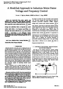
familiar equivalent circuit for the steady state analysis of squirrel cage induction motor modifies as shown in Figure 1 below.
smax/ min ; where smax/ min are values of slip at which Tmax/ min occur. Therefore,
Is
I
rs
jaxls aE ar
Vs
' r
jaxlr' jax I mm
rr' s
Figure 1: Steady State Equivalent Circuit of a Squirrel Cage Induction Motor for Constant Flux Control (a ≤ 1). The per unit frequency ‘‘a’’ is defined as,
a=
fs
=
f rated
ωs ωs = ωb ωsr
Where Ear , is the rated induced voltage or back emf. For constant I m ,
(2)
Next, the motor operation for this constant flux control is examined. Under this operating condition, the rotor referred current is
Ir' =
aEar ' r 2
r ( ) + (axlr' )2 s
=
Ear ' r
(3)
r ( )2 + ( xlr' )2 as
The resulting motor torque is:
3P ' 2 rr' 3P rr' Ear2 (4) Tem = ( Ir ) = 2aωsr s 2ωsr as rr' 2 ' 2 ( ) + (xlr ) as The Pacific Journal of Science and Technology http://www.akamaiuniversity.us/PJST.htm
rr' axlr'
Substituting
smax/ min for s in Equations 4,
Tmax/ min = ±
3P Ear2 4ωsr xlr'
(5)
(6)
The effect of the term ‘‘as’’ is obvious in Equations 3 and 4. It is seen that if ‘‘as’’ is maintained constant, then
I r' and Tem are
maintained constant analogous to armature voltage control of dc motor up to rated speed. From Equation 6, it can be seen that Tmax/ min is independent of ‘‘as’’ and that
(1)
E' E = ar ≡ E ' = aEar axm xm
smax/ min = ±
Tmax is equal to
Tmin in magnitude. Table 1: Sample Machine Data. Rated Voltage Winding Connection Rated Frequency Number of Poles Rated Speed Stator Resistance Rotor Referred Resistance Stator Reactance Rotor Referred Reactance Magnetizing Reactance
400V Star 50Hz 6 960rpm 0.4Ω 0.2Ω 1.5Ω 1.5Ω 30Ω
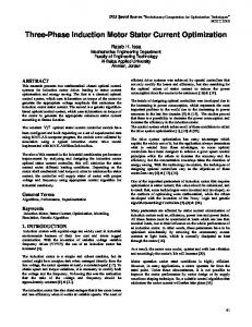
Figure 2 shows the Torque-Per Unit Frequency Curves of the Sample Motor of Table One under Constant Flux Control, at a ≤ 1. This control strategy applies up to the rated stator voltage V s = V sr at the rated frequency. Above the rated frequency, a>1, constant at
V s must be kept
Vsr to avoid damage to insulation. –45– Volume 10. Number 1. May 2009 (Spring)
From analysis,
Tmax/ min =
3P Vsr2 4aωsr (rs ± rs2 + a 2 xL2 )
(9)
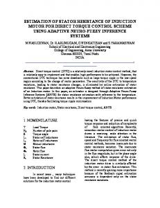
Figure 4 shows the Torque-Per Unit Frequency Curves of the Sample Motor of Table 1 for control above rated speed (a ≥1).
Figure 2: Torque-Per Unit Frequency Curves for Constant Flux Control (a ≤ 1).
For control above base speed, where a >1, I m is no longer constant but decreasing with increase in frequency. This implies increased magnetizing reactance and continuous decrease in magnetizing current. The approximate equivalent circuit is, therefore, used for analysis in this region of operation. The magnetizing reactance is transferred to the input terminal as shown in Figure 3.
Vsr
rs jaxm
jaxls
jaxlr'
rr' s
I r'
Figure 3: Approximate Equivalent Circuit for Control above Rated Speed (a ≥ 1).
Figure 4: Torque-Per Unit Frequency Curves for Control above Rated Speed (a ≥ 1). The problem with direct implementation of constant flux drive is that flux (especially magnetizing flux or current) cannot be directly measured due to the lumped nature of winding parameters. Drive engineers have tried to solve this problem by using the constant
v control f
strategy which permits the indirect control of flux. Under this operating condition, the rotor referred current and the motor torque are, respectively, as shown below.
(rs + Tem =
rr' 2 ) + a 2 xL2 s
3P rr' 2ωsr as
Vsr2 (rs +
v CONTROL: PRINCIPLES AND f
MOTOR PERFORMANCE
Vsr
I r' =
BASIC
' r 2
r ) + a 2 xL2 s
The Pacific Journal of Science and Technology http://www.akamaiuniversity.us/PJST.htm
(7) The approximate equivalent circuit is adopted for the basic (8)
v control analysis as shown in Figure f
5.
–46– Volume 10. Number 1. May 2009 (Spring)
s m ax / min = ±
rs jaxm
aV sr
jaxls
jaxlr'
rr' s
I r'
Figure 5: Approximate Equivalent Circuit for Basic
fs
to rated frequency ratio
= a multiplies the
f rated rated terminal voltage Vsr and all inductive reactances. Where, f rated , is the rated frequency.
(13)
r ( s ) 2 + ( x ls + x lr' ) 2 a
Finally, the maximum and minimum torque for operation at a ≤ 1 is obtained as:
Tmax/min =
v Control (a ≤ 1). f
In the equivalent circuit, the operating frequency
rr' a
Vsr2 3P (14) 4ωsr rs rs 2 ( ± ( ) + (xls + xlr' ) 2 ) a a
The ‘‘+’’ sign is for maximum torque while the ‘‘– ’’ sign is for minimum torque. Figure 6 shows the Torque-Per Unit Frequency Curves of the Sample Motor of Table One under Basic
v Control at a ≤1. f
It is deduced from Figure 5, that:
aV sr
I r' = ( rs +
(10)
' r
r 2 ) + a 2 ( x ls + x lr' ) 2 s
From this, the operating torque
Tem =
3P rr' 2aωsr s
To
obtain
Tem is derived as:
a 2Vsr2
(11)
rr' 2 2 (rs + ) + a (xls + xlr' ) 2 s the
slip
s max/ min
at
which
maximum/minimum torques occur, the first slip derivative of the operating torque, Tem , is equated to zero.
dTem =0 ds It is obtained, therefore, that
The Pacific Journal of Science and Technology http://www.akamaiuniversity.us/PJST.htm
Figure 6: Torque-Per Unit Frequency Curves for Basic
v Control (a ≤ 1) f
With this approach, for 0 ≤ a ≤ 1 , the magnetizing current I m is far from being constant (12)
at low speeds because of large drops in the stator impedance when compared to aVsr . Hence the need for modifications to compensate for this stator impedance drops at low frequencies [10].
–47– Volume 10. Number 1. May 2009 (Spring)
MODIFIED
v CONTROL STRATEGY AND f
Where
I m + I r' = (
EXAMPLE MOTOR PERFORMANCES To make full use of the motor torque capability at the start and at low speed, the
v ratio is f
increased to sustain magnetizing flux at its rated value thereby compensating for the stator resistance drop at low frequencies associated
v control. The stator voltage is f
with the basic
jEar aE + ' ar ) xm rr + jaxlr' s
(17)
Therefore,
Vs = aEar + (rs + jaxls )(
jEar E + ' ar ) xm rr + xlr' as
(18)
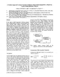
Equation 18 is plotted as ‘‘a’’ varies in the range 0.1≤a≤1. The result is shown in Figure 8 below.
adjusted according to Equation 15.
Vs = V0 + Ka
(15)
This stator voltage is composed of two components. One is a constant term which is an off-set voltage and the other is a frequency dependent component. Where even at zero frequency, Vo compensates for the drop in stator series impedance to make the magnetizing current equal to its rated value. Where, a, is the per-unit frequency and Vo is the stator voltage chosen to give rated magnetizing current at zero speed. Now, to determine Vo and K , the voltage relationships in the exact equivalent circuit of Figure 7 is analyzed.
rs Vs
jaxls aE ar
jaxlr' jax I mm
rr' s
v Control. f
The constant, K, in Equation 15 is the slope of Figure 8 while V0 is obtained by extrapolating the straight line and intersection at a=0.
I r'
Is
Figure 8: Look-Up Plot for Modified
determining
the point
of
The slope, K, is obtained as 217.614 and V0 obtained as 13.3261V (through extrapolation at a =0) Then, Equation 15 modifies to
Vs = 13.3261 + 217.614a Figure 7: Steady State Equivalent Circuit of a Squirrel Cage Induction Motor for Variable Voltage and Frequency Control.
(19)
It is seen that even at zero frequency (a=0), the low frequency boost-voltage V s = 13.3261V compensates for the stator impedance drop.
From Figure 7,
Vs = aE ar + ( I m + I r' )(rs + jax ls )
The Pacific Journal of Science and Technology http://www.akamaiuniversity.us/PJST.htm
(16)
Under this condition, the control characteristics are examined as a varies from 0.1 to 2 using the approximate equivalent circuit of Figure 9.
–48– Volume 10. Number 1. May 2009 (Spring)
PERFORMANCE COMPARISM BETWEEN THE ' + Ir
rs
jaxls
jax
' lr
BASIC AND THE MODIFIED
rr' s
V s = 13.3261 + 217.614a _
v CONTROL f
STRATEGIES Due to the stator impedance drop at low frequencies associated with the basic
Figure 9: Approximate Equivalent Circuit for Modified
v Control Strategy. f
v control, f
the magnetizing flux and current gradually increases to rated values as frequency tends to rated. This leads to a corresponding gradual increase in the motor developed torque up to rated value at rated frequency. The complete drive strategy, as programmed in MATLAB®, is shown in Figure 11.
'
From Figure 9, I r and Tem are obtained as follows:
For the modified
Vs
I r' = (rs +
Tem
(20)
' r 2
r ) + a 2 xL2 s
3P rr' = 2ω sr as
V s2 r' (rs + r ) 2 + a 2 x L2 s
(21)
v control strategy where the f
low frequency boost voltage is injected to sustain the magnetizing flux thereby compensating for the stator resistance drop, at the maximum permissible current the drive operate essentially at a constant flux, providing constant torque operation from zero to rated speed [10]. The complete drive strategy, as programmed in MATLAB®, is shown in Figure 12.
Where, xL = xls + xlr '
Figure 10 shows the Torque-Per Unit Frequency Curves of the sample motor of Table One under the Modified
v Control. f
Figure 11: The Complete Drive Strategy for Basic
v Control. f For both the basic and the modified Figure 10: Complete Torque-Per Unit Frequency Curves for Modified
v Control. f
The Pacific Journal of Science and Technology http://www.akamaiuniversity.us/PJST.htm
v drives f
strategies, the motor is driven beyond base speed by increasing the frequency further. However the voltage applied cannot be increased beyond rated value to avoid insulation breakdown.
–49– Volume 10. Number 1. May 2009 (Spring)
allows the constant v
f
control to operate up to
the rated speed beyond which the motor terminal voltage is kept constant at its rated value to avoid damage to motor insulation. A comparison of the complete drives strategies of the basic and the modified v
control methods, which describe
f
the operation of the machine in a wide frequency range, were undertaken and the results, as shown in Figure 11 and Figure 12, confirms the modified
v
f
control
as
a
very
good
approximation to the idealistic constant flux control. Figure 12: The Complete Drive Strategy for
v Control. Modified f There are some applications, like traction, in which speed control in a wide range is required and the torque demand in the high-speed range is low. For such applications, control beyond the constant power range is required. To prevent the power from exceeding breakdown torque, the machine is operated at a constant slip speed and the machine current and power are allowed to decrease as shown in Figures 11 and 12. Now, the motor current and torque decreases inversely with the speed. This characteristic is often called the series motor characteristic. For speed below rated, the voltage and frequency are reduced with speed to maintain the desired
v ratio or f
constant flux, and to keep the operation on the portion of the speed-torque curves with a negative slope.
CONCLUSION The modified
v
f
control strategy, the central
theme of which is the injection of low frequency boost-voltage, offers the opportunity to realize maximum torque from zero to rated speed, thereby compensating for the low frequency stator impedance drops associated with the basic
v
f
control. The control strategy generally
The Pacific Journal of Science and Technology http://www.akamaiuniversity.us/PJST.htm
REFERENCES 1.
Leonhard, W. 1995. ‘‘Controlled AC Drives, A Successful Transfer from Ideas to Industrial Practice’’. CETTI 95. Brazil, pp. 1-12.
2.
Okoro, O.I. 2005. ‘‘Dynamic Modelling and Simulation of Squirrel-Cage Asynchronous Machine with Non-Linear Effects’’. Journal of ASTM International. 2(6):1-16.
3.
Daniel, L. and T. K. Philip. 2002. Control of Induction Machine Drives. CRC press LLC, Illinois.
4.
MacDonald, M.L. and P.C. Sen. 1979. ‘‘Control Loop Study of Induction Motor Drive Using D-Q Model’’. IEEE Transaction on Industrial Electronics and Control Instrumentation. 26(4):237-241.
5.
Ostovic, V. 1994. Computer-Aided Analysis of Electric Machines. Prentice Hall International (UK) Ltd.: London, UK.
6.
Okoro, O.I. 2004. ‘‘MATLAB Simulation of Induction Machine with Saturable Leakage and Magnetizing Inductances’’, Botswana Journal of Technology. 13(2): 20-28.
7.
Fitzgerald, A.E. 1990. Electric Machinery. 5th Edition, McGraw-Hill Inc.: New York, NY.
8.
Marino, R., S. Peresada, and P. Valigi. 1993. ‘‘Adaptive Input-Output Linearizing Control of Induction Motor’’. IEEE Transaction on Automatic Control, 38(2): 208-221.
9.
Zhou, K. and D. Wang. 2002. ‘‘Relationship Carrier-Based Vector Modulation and Three Phase Carrier-based PWM: A Comparative Analysis’’. IEEE Trans. Industrial Electronics. 49(1): 186-195.
–50– Volume 10. Number 1. May 2009 (Spring)
10. Bose, B.K. 1997. Power Electronics and Variable Frequency Drives. IEEE Press, New York, NY. 11. Hussein, S. and R. Issa. 2006. ‘‘Improving Mechanical Characteristics of Inverter-Induction Motor Drive System’’. American Journal of Applied Sciences.3(8):1961-1966. 12. Alfredo, M.G., T. Lipo and D.W. Novotny. 1998. ‘‘A New Induction Motor V/F Control Method Capable of High-Performance Regulation at Low Speed’’, IEEE Trans. Ind. Application. 34(4):813-820. 13. Sepe, S. and L. Lang. 1994. ‘‘Inverter NonLinearities and Discrete-Time Vector Current Control’’. IEEE Trans. Ind. Application. 30(1): 6270. 14. Agu, M.U. 2007/2008 Session. ‘‘Electric Machine Drives’’. Unpublished Course Notes for EE 614, Department of Electrical Engineering, University of Nigeria, Nsukka.
metals (melting, casting, forging, forming, annealing, hardening), Renewable Energy Sources (especially in the area of working with solar photo voltaic cells and panels to realize solar lighting, heating, battery charging and water pumping), Power System Distribution for Residential, Commercial and Industrial Areas.
SUGGESTED CITATION Ogbuka, C.U. and M.U. Agu. 2009. “A Modified Approach to Induction Motor Stator Voltage and Frequency Control”. Pacific Journal of Science and Technology. 10(1):44-51.
Pacific Journal of Science and Technology
ABOUT THE AUTHORS Engr. Ogbuka, Cosmas Uchenna received his B.Eng. (First Class Honors) and M.Eng. degrees in 2004 and 2008, respectively, in the Department of Electrical Engineering University of Nigeria, Nsukka where he presently works as a Lecturer/Research Student. His research interests are in Adjustable Speed Drives of Electrical Machines: (DC and AC Electric Machine Torque/Speed Control with Converters and Inverters) and Power Electronics. Engr. Prof. Agu, Marcel U. obtained his B.Sc. in Electrical Engineering in 1974 in the University of Nigeria, Nsukka. He also received his M.A.Sc. and Ph.D. in 1978 and 1982, respectively, in Power Electronics from the University of Toronto, Canada. He is a Professor of Power Electronic in the Department of Electrical Engineering University of Nigeria, Nsukka. His research interests are in, but not limited to, Power Electronic Circuits (Solid State AC/DC and DC/DC Converters, Inverter Circuits and Cycloconverter/inverter circuits), Static Electric Motor Drives (DC and AC Electric Machine Torque/Speed Control with Converters and Inverters), Analogue, digital and microprocessorbased electronic control circuits, Static Induction Heating Power Supplies for heat treatment of
The Pacific Journal of Science and Technology http://www.akamaiuniversity.us/PJST.htm
–51– Volume 10. Number 1. May 2009 (Spring)