The concept of fixture reconfigurability was first developed in the Federal .... flected light intensity is below a threshold value, an OFF signal is sent to the ...
B. Benhabib Assistant Professor.
K. C. Chan Graduate Student.
M. Q. Dai Senior Designer.
A Modular Programmable Fixturing System
Computer Integrated Manufacturing Laboratory, Department of Mechanical Engineering, University of Toronto, Toronto, Ontario, Canada M5S 1A4
1
Introduction A fixture is a production tool that locates, and holds a workpiece securely so that the required manufacturing operations can be performed [1]. Fixtures can be classified as dedicated or reconfigurable. Dedicated fixtures generally imply that they have been designed for a specific workpiece geometry and/or manufacturing operation. These types of fixtures are most suitable for mass production environments, where they can be discarded at the end of the product life and their costs can be absorbed by the large number of products. Reconfigurable fixtures, on the other hand, generally imply that they have been designed for a family of workpiece geometries and/ or manufacturing operations. These types of fixtures are most suitable for batch and production and job-shop environments, where they can be used by many different products. The concept of fixture reconfigurability was first developed in the Federal Republic of Germany [2], where such fixtures consisted of kits of standard modular components such as locators, V-blocks, and clamps assembled on a baseplate. Currently available commerical modular fixturing systems, based on this approach, include the Warton Unitool System, the Haider Jig and Fixturing system, and the Bluco Technik fixturing system [3, 4, 5]. These systems, however, lack "intelligence" in the form of sensory feedback capability and programmability. Some of the more recent research results are presented below to give an insight to the state-of-the-art in reconfigurable fixtures. The modular programmable conformable clamping system developed by M. R. Cutkosky, et al. was designed for fixturing a variety of turbine blade forgings during their machining [6]. The clamps consist of hinged octagonal frames which may be positioned at almost any position along the blade. The lower half of each clamp employs pneumatic plungers which, when released, are free to conform to the profile of the turbine blade. With the plungers pressed against the blade, a high strength belt is wrapped over the convex surface of the blade to hold Contributed by the Production Engineering Division for publication in the JOURNAL OP ENGINEERING FOR INDUSTRY . Manuscript received June 1989; revised March 1990.
it against the plungers in the lower half of the clamp. The programmability of this device is of only open-loop type, where information about the status of the fixturing process is not transmitted back to the computer. The automatically reconfigurable fixture developed by H. Asada and A. B. By was specifically designed for assembly [7]. This modular fixture includes locating pins (locators), guides, and clamps, which can be stored in magazines. The main limitation of this fixture is that the baseplate, on which the fixture is configured, is a magnetic chuck, and therefore, only useful for nonmagnetic workpieces. The modular fixturing system developed by J. L. Colbert et al. was primarily designed for the machining of prismatic workpieces, [8]. This fixture includes a baseplate, tool point units, and clamps. The baseplate has two sets of hole patterns, one for the mounting of the tool points and clamps, and the other for hydraulic fluid supply to the clamps. The tool point unit is equipped with a microswitch activated by the motion of the tool point when a workpiece is in contact. This fixture design is not entirely flexible, in the sense that, it uses workpiece specific mounting blocks along with modular standard clamps and locators. The reconfigurable fixture developed by K. Youcef-Toumi et al. was specifically designed for the drilling of sheet metal parts [9]. This fixture includes a baseplate, vertical supports, and locating pins. The main concept is to support the sheet metal part from beneath with vertical supports on a fixture baseplate. The baseplate is a flat plate with evenly spaced Tslots. The height of the vertical supports can only be adjusted by discrete amounts. Similar to other systems, this system cannot provide a controller with possible feedback information from the fixture. The automatic modular and adaptable fixture developed by J. H. Buitrago and K. Youcef-Toumi consists of multipin modules that can conform to the workpiece geometry [10]. The modules consist of three main parts: array of pins, a Shape Memory Alloy (SMA) actuator, and a modular interface. Once all the modules are located on the baseplate, and the workpiece is positioned on the fixture, the (shape memory alloy) clamping FEBRUARY 1991, Vol. 113/93
Journal of Engineering for Industry
Copyright © 1991 by ASME Downloaded From: http://www.asmedl.org/ on 09/23/2013 Terms of Use: http://asme.org/terms
actuator is first commanded to release the pins to conform to the surface of the workpiece, and then commanded to clamp the pins so that the adaptable surface becomes rigid. The mechanical design of this fixture is complicated in comparison to other systems, and it does not incorporate any sensors. Most fixturing systems reviewed in this section had been either developed for a specific purpose or limited in number of applications. Sensor integration has always been considered as the last step, or completely ignored due to the complicated designs of the systems. The objective of our research was therefore set as "to develop a modular fixturing system (hardware/software) with some built-in flexibility, for robotic assembly (in relatively clean environments)" with the following basic features: modularity, automatic reconfigurability, sensory feedback, and programmability through a computer interface. This paper presents the results of this research. Design Requirements and Conceptual Design The Modular Programmable Fixturing System (MPFS) presented in this paper is designed and developed for assembly operations only. The basic design simplification for assembly fixtures, as opposed to machining fixtures, is the lack of consideration for high cutting forces or liquid coolants that exist during most machining operations. According to an analysis of the typical robotic assembly tasks, almost all assembly operations occur along the vertical direction, layered assembly [11]. Therefore, our design efforts of the MPFS concentrated on the development of fixture components mainly for vertical assembly of workpieces.
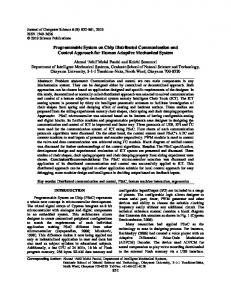
LIGHT EMnTER
OPTICAL FIBERS LIGHT RECEIVER
2
0 Fig. 1
DISTANCE TO REFLECTIVE SURFACE Y-guide configuration, and output graph
decision to be made in designing the MPFS was the interface between the modular components (locators, clamps, etc.) and the baseplate. The two basic types of baseplate geometries considered were the T-slot and the hole type [12]. The hole type baseplate is more suitable for the automatic reconfigurability of the fixture, since the robot would be required to 2.1 MPFS Design Requirements. The design requirements perform only vertical, "peg-in-the-hole" operations. Whereas, of the MPFS are presented in this section under two categories: for the T-slot type baseplates, the insertions of components the general requirements pertinent to the design of any fixture have to be sideways. [4]; and, the specific requirements pertinent to the design of Sensor integration is also easier in a hole type baseplate, the MPFS. since the interfaces can be located at fixed locations directly under the holes. For T-slot type baseplates, since the locations General Design Requirements of components can be continuously varied along the slots, the (1) Positive location: the workpiece must be located and re- sensors have to designed accordingly. Although the hole type stricted from all possible motion. baseplate would constrain the fixture components to only cer(2) Rigidity: the workpiece must be held securely against ex- tain discrete locations, flexibility can be achieved by designing ternal forces. modules with some adjustable features to compensate for this (3) Ruggedness: the fixture must be able to endure wear and disadvantage. Based on these factors the hole type baseplate shock forces during contact with the workpiece, where fixture was chosen for the MPFS design. components that are subject to damage should be easily reThe following inventory of components, which can be replaceable. configured on the hole type baseplate, was envisioned to yield (4) Repeatability: identical workpieces should be located in an effective MPFS: precisely the same location on repeated loading/unloading (/) Horizontal locators: for external profile support. cycles. (2) Vertical locators: for external support from underneath. (5) Low profile: the fixture components must not obstruct the (3) V-block: for external profile support of cylindrical workmanufacturing path. pieces. (6) Minimum distortion of workpieces: the clamping forces (4) Universal clamp: for clamping workpieces in any direction. should not cause any bending or damage to the workpiece. The mechanical designs and functional aspects of these com(7) Tolerance to small variations in workpiece geometry: the ponents, as well as the baseplate, will be discussed in Section fixture should be tolerant to minor size variations in workpieces 3. that are manufactured using processes such as casting. (S) Reliability: high level of reliability achieved by minimizing 2.2.2 Sensor Integration. The purpose for sensor integrathe number of movable components in the fixture. tion into the above fixture components was three-fold: (i) Verification of the proper insertion of the fixture comSpecific Design Requirements ponents into the baseplate. (7) Modularity: the fixture must be composed of standard (2) Detection of the workpiece presence. modules, which can be assembled on a baseplate. (3) Control of the clamping process. (2) Automatic reconfigurability: the fixture must be reconfigIn this research, three types of transducers, namely the pieurable by a robot (i.e., the fixture components should be dezoresistive, the piezoelectric, and the electro-optical transsigned for robotic assembly). ducers were considered. The electro-optical transducer was (5) Sensory feedback controllability: the fixture components selected to be used in the fixture component designs based on must be integrated with sensors for feedback control. the following advantages [13]: (4) Programmability: the operation of the fixture must be (7) freedom from electro-magnetic interference and electroprogrammable by a computer. magnetic pulses, (2) passive operation (no electronics or power required at the 2.2 Conceptual Design sensing point), 2.2.1 Mechanical Design of Fixture Components. The first (3) insensitivity to temperature, and, 94 / Vol. 113, FEBRUARY 1991 Downloaded From: http://www.asmedl.org/ on 09/23/2013 Terms of Use: http://asme.org/terms
Transactions of the ASME
UPPER RUBBER SPRING CONTACT COVER REFLECTOR'ROD HOLDER REFLECTOR ROD LOWER RUBBER SPRING
LOCATOR BODY
ELECTRO-MAGNETIC COIL ELECTRICAL WIRES TEETH-INCORPORATED FERRO-MAGNETIC INSERT
OPTICAL FIBERS
Fig. 2
Horizontal locator
(4) simple electro-optical interfaces. The electro-optical Y-guide distance sensor was selected to be incorporated into the fixture components as a "proximity sensor," [14]. This design uses two optical fibers positioned across an orthogonal surface, with one end coupled to an emitter, and another to a receiver. The approximate light intensity output of this sensor is shown in Fig. 1. However, since the proximity sensor for the MPFS is not intended to measure distance, rather to provide a signal to indicate whether an object is in its close vicinity, it has to be implemented in a binary format. To achieve this objective, the analog signal received from the sensor is digitized such that, when the reflected light intensity is below a threshold value, an OFF signal is sent to the controller; otherwise, an ON signal is sent. Therefore, as an object approaches the sensor from a distance, and touches the sensor, an OFF/ON/OFF signal sequence should be received by the controller. This signal sequence implies that an object is close-by or touching the sensor. The application of this scheme to the MPFS will be discussed in Section 3. It should be noted that reflecting surfaces must be periodically cleaned to avoid incorrect signal interpretation. 2.2.3 Computer Interface. The sensing and clamping operations of the MPFS are to be controlled by a personal computer (PC) through a remote interface circuit. In this scheme, the digital command signals are to be sent from the PC to the remote interface, for the initiation of the clamping operation for example, through the PC's parallel port, while analog signals from the sensors are received through an Analog to Digital board (ADDA card), located in the PC. Software programs have to developed for the input/output signal processing and the control of the fixturing process, namely for component insertion verification, workpiece presence detection, and clamp actuation. 3 Mechanical Design of the MPFS 3.1 Horizontal Locator. The horizontal locator consists of a cap, a contact cover, a reflector rod and its holder, two rubber springs, and a locator body, Fig. 2. It is chamfered for ease of insertion, and a slot is incorporated for ease of robotic handling. A long contact cover which provides a larger height range for workpiece contact sensing is incorporated into the design. This contact cover consists of a long tube and a cylindrical part attached by screws. The reflector rod is held by its holder and is connected to the cap. It can be deflected aoout the center point of the reflector rod holder when it is pushed horizontally by the contact cover. The upper rubber spring
Fig. 3
Horizontal locator in contact with a workpiece
prevents the contact cover from moving freely, and provides a continuous force to ensure that it is in contact with the top surface of the locator body. The bottom rubber spring is used to retain the central position of the reflector rod. This design has the advantage that the locator can be inserted into the baseplate hole at any orientation, due to its axisymmetric nature. Therefore, a locking mechanism for avoiding rotation of the locator in the baseplate hole is not required. However, a locational clearance fit (H7/h6), which provides accurate snug fit but free assembly has to be employed, [15]. In this design, the sensing scheme utilizes the Y-guide proximity sensor concept discussed in the previous section. The optical fibers are housed in the baseplate hole and the light emitter and receiver are placed remotely outside the baseplate. Prior to the insertion of the locator into the baseplate hole, the controller receives an OFF signal corresponding to the weak ambient light. As the locator is inserted, an ON signal is received when the increased light intensity reflected from the bottom surface of the reflector rod inside the locator reaches a threshold value. A calibration has to be carried out to determine this threshold level. When a workpiece is placed against the locator at any orientation, the contact cover shifts horizontally to deflect the reflector rod, thus causing the reflected light intensity to drop significantly from an ON level to an OFF level, to indicate workpiece presence, Fig. 3. This sensing scheme requires a minimal force to overcome the spring stiffnesses of rubber springs in order to move the contact cover, and thus, actuate the sensor. This design allows workpiece presence detection along almost the full height of the locator—this feature can be considered as built-in flexibility. , 3.2 Vertical Locator. The pneumatic type vertical locator is of variable-height—this feature can be considered as built-in flexibility. It consists of a piston, two O-rings, eight ball bearings, a steel ring, a wedge, a sensing pin, a lock cap, a lock nut, and a reflector, Fig. 4. The locator is chamfered for ease of insertion, and a slot is incorporated for ease of robotic handling. The piston in the locator can move vertically for height adjustment, where a self-locking mechanism is employed to hold it at the required height. The piston lock contains the O-
Journal of Engineering for Industry Downloaded From: http://www.asmedl.org/ on 09/23/2013 Terms of Use: http://asme.org/terms
FEBRUARY 1991, Vol. 113/95
(.)
(iii)
Fig. 4
(iv)
Variable-height vertical locator
Fig. 6
Fig. 5
VARIABLE-HEIGHT LOCATOR
Vertical locator in contact with a workpiece
ring, the ball bearings, the wedge, and the steel ring. As the ball bearings are in a lower position, the piston is locked by friction. When the steel ring pushes the ball bearings upward, the lock is released and the piston can move freely. This variable-height vertical locator is more flexible than a fixed-height locator, though, at the expense of design complexity. The sensor configuration that was used for the horizontal locator was also used for the vertical locator in order to achieve a standard interface mechanism between the fixture components and the baseplate. The only difference is that when a workpiece is located on top of the vertical locator, the reflector moves downward instead of deflecting sideways to cause drop in reflected light intensity, Fig. 5. The sensing pin is connected to the reflector by means of a small O-ring. This O-ring allows the sensing pin to stay at a specific height by providing a frictional force, as well as to move to another height when a sufficient external force is applied. The lock cap and nut are used to achieve the required friction level by compressing the small O-ring. An air exhaust hole is incorporated in the reflector so that the sensing pin can be pulled/pushed smoothly. 9 6 / V o l . 113, FEBRUARY 1991
Vertical locator height setting procedure
When the locator is inserted into a baseplate hole successfully, an OFF-ON signal sequence is received. When a workpiece is placed on the locator, the sensing pin and the reflector move downward together to block the reflected light, thus an ON-OFF signal sequence is received to indicate workpiece presence. The desired height of the locator is set with an external device prior to its insertion into a baseplate hole. The base of the height setting device contains a hole for supply of air, and two O-rings for sealing. The height adjustment process, as illustrated in Fig. 6, is as follows: (/) The locator is inserted into the height setting mechanism baseplate hole. (2) Air is injected into the locator through the air inlet to release the lock by pushing the ball bearings upward, and allow the piston to move freely. (5) The air pressure is greater than the friction holding the sensing pin in the reflector, thus it forces the piston and the sensing pin to move upward, and the reflector to move downward. (4) The piston continues to move upward and the reflector continues to move downward until the piston is constrained by the external height setting device and the reflector by the base. (5) The supply of air is then halted and the piston is locked at the required height by the locking mechanism. The O-ring provides a frictional force to prevent the piston from moving downward before it is locked, and a downward spring force to push the bearings to lock the piston. (6) Lastly, the height setting device can be removed, to release the sensing pin and the reflector, which are held together by the friction supplied by the small O-ring. 3.3 V-block. The V-block is of variable-width type (but not of variable-height type) and consists of a fixed jaw, a movable jaw, a T-slide, a reflector, a spring-loaded pin, and a teethTransactions of the ASME
Downloaded From: http://www.asmedl.org/ on 09/23/2013 Terms of Use: http://asme.org/terms
Fig. 7
Variable-width V-block
(0
(.1)
woKKi'ihri-:
10 HOLES
Fig. 9
V-block width setting procedure
(7) The spring-loaded pin is pressed so that its larger diameter end can be released from the hole. (2) The movable jaw, now freed, can be relocated by sliding it along the T-slide to another predetermined hole location. (5) The movable jaw can be fixed at the new location by releasing the pressed pin, which in turn causes the pin's larger diameter end enter the new hole. Fig. 8
V-block in contact with a workpiece
incorporated base, Fig. 7. The base is chamfered for ease of insertion and designed to be adjusted and handled by a robot. Unlike the locators, the location of the V-block on the baseplate is "directional," (i.e., the orientation of the V-block must be predetermined). Therefore, a teeth-incorporated electro-magnetic locking mechanism was designed to prevent the V-block from rotating during the fixturing process once it is inserted into the baseplate. The magnetic field does not affect the fixturing of ferro-magnetic workpieces, since the ferromagnetic base is isolated to the bottom part of the V-block. The locking mechanism consists of a coil and teeth-incorporated ferro-magnetic insert in the baseplate hole, onto which the corresponding teeth-incorporated base of the V-block meshes. Electrical wires are connected to the coil through a hole under the baseplate. When the V-block is inserted into the baseplate hole at the correct orientation, power is supplied to the coil to generate the necessary magnetic field (a normal force) to hold the V-block in place. The teeth ensure that the V-block does not rotate about the vertical axis during the fixturing process. In this design, the number of teeth solely depends on the resolution required for locating the V-block on the baseplate. The sensing scheme for the V-block is the same as for the vertical locator. As the V-block is inserted into a baseplate hole successfully, an OFF-ON signal sequence is received. When a cylindrical workpiece is placed on the V-block, the reflector moves downward to block the reflected light, thus, an ONOFF signal sequence is received to indicate workpiece presence, Fig. 8. The desired width of the V-block must be set before it can be used for locating workpieces. The width setting mechanism consists of a spring-loaded pin, and the larger diameter of a pin, which is inserted into any one of the ten holes along'one of the sides of the middle part of the T-slide. The width adjustment procedure, as illustrated in Fig. 9, is as follows:
3.4 Universal Clamp. A five dof universal clamp that can clamp workpieces at any direction is designed to substitute for horizontal and vertical clamps, which can be used only in single directions, though, at the expense of structural complexity— this feature can be considered as built-in flexibility. This clamp consists of two 2-dof (degree-of-freedom) and one 1-dof joints, a pneumatic cylinder, an exchangeable clamp head, a sensor line, and five locating pins, Figs. 10 and 11. The two 2-dof joints consist of identical collet locking mechanisms [16], allowing linear and rotary motions along and about the vertical and the horizontal directions. The 1-dof joint consists of one collet locking mechanism. This joint holds the pneumatic cylinder and the sensing pin and allows it to rotate about the center line of the collet mechanism. The "five-legged" base of this universal clamp consists of five press-fitted locating pins, with ferro-magnetic bases. The clamp is located on the baseplate through these five pins. The standard electro-magnetic locking mechanism designed for the V-block is used for the universal clamp without the teeth. The combined magnetic field generated in the five holes is sufficient to hold the clamp in the baseplate rigidly. The magnetic field does not affect the fixturing of ferro-magnetic workpieces, as for the previous designs, since the ferro-magnetic inserts are isolated to the bottom part of the locating pins. The sensing scheme for the verification of the insertion process is the same as for the previous designs. When the clamp is inserted into the baseplate, an OFF-ON signal sequence is received at the center locating pin hole to indicate successful clamp insertion. The workpiece detection scheme of this universal clamp, however is different from the previous designs. A flexible wire housed inside the sensor line and the base link connects the sensing pin to the reflector at the base. The sensing procedure is as follows, Fig. 12: (7) Air is supplied to actuate the pneumatic cylinder of the clamp. (2) When the workpiece is clamped, the reaction force causes the sensing pin to move away from the wedge. (5) Consequently, the flexible wire inside the sensor line moves
Journal of Engineering for Industry Downloaded From: http://www.asmedl.org/ on 09/23/2013 Terms of Use: http://asme.org/terms
FEBRUARY 1991, Vol. 113/97
SPRING
COLLET
SENSOR LINE
1 dof JOINT
PNEUMATIC CYLINDER
Fig. 13
Collet locking mechanism and operation
LOCATING PINS
Fig. 10
Universal clamp (isometric view)
TEETH-INCORPORATED EERRO-MAGNETIC INSERT
I ... i\
OPTICAL FIBERS
ELECTRICAL WIRES
Fig. 14
Fig. 11
Universal clamp (orthographic views)
wt^p c_::::i Fig. 12
Universal clamp in contact with a workpiece
along its tube, which in turn causes the reflector to move downward. Therefore, the light-reflected to the receiving fiber is blocked and an ON-OFF signal sequence is received to indicate workpiece presence. The collet locking mechanisms, incorporated into the joints
Baseplate
are used for changing the clamp configuration, (each) consist of a collet, a wedge, four springs, and a coil, Fig. 13. The operation of the collet locking mechanism is as follows: (/) Power is supplied to the coil for generating a magnetic field to attract the wedge, thus compressing the four springs and letting the collet to open. (2) The joint is rotated and/or moved linearly to set the desired configuration. (3) Lastly, the supply of power is halted, letting the springs push the wedge back to its original position to close the collet. 3.5 Baseplate. According to the fixture component designs (horizontal locator, variable-height vertical locator, variablewidth V-block, and universal clamp) presented in this section, a baseplate that consists of a matrix of accurately machined standard interface holes was designed. Every hole contains a teeth-incorporated ferro-magnetic insert, which houses a coil, two optical fibers, and two electrical wires, Fig. 14. The hole is chamfered for ease of component insertion. The optical fibers, and the electrical wires from all the holes are connected to a remote interface board which in turn is connected to a PC. The two optical fibers are located at the center of the ferromagnetic insert for the transmitting and receiving light Y-guide. One fiber is connected to a remote light emitter, and another to a remote light receiver. Combined with the light emitter and receiver, these two fibers are used for verification of component insertion and workpiece presence detection. To accomplish these, the emitter is first powered and the receiver receives an OFF signal corresponding to the ambient light. As a component is inserted into the hole, the reflected light intensity increases to its maximum, thus an ON signal is received to
98 / Vol. 113, FEBRUARY 1991 Downloaded From: http://www.asmedl.org/ on 09/23/2013 Terms of Use: http://asme.org/terms
Transactions of the ASME
Fig. 17
orr
O~
SIC:\AL RECEIVED
Horizontal clamp
SIGNAL RECEIVED "DUMMY' LOCATOR
SENSOR INTEGRATED LOCATOR
(,,)
(i)
SOl.ES'OID VALVE
REFLECTOR \10\'£S DOW:-.iWARD OR DEFLECTS SIDEWAYS
---r-;;~PlJT
I I
CONTROL VALVE
~l ADDA PORT
O;.J
SIC~AL
Off SIC:-"AL RECE1VI::D
REC£IVF:D
TRA~S.\lIT
LIGHT
PARALLf.:L PORT
Fig. 15 (a) Component insertion verification, (b) Workpiece presence detection
IBM PC-AT
FIXTURE CONTROLLER
REMOTE INTERfACE CIRCUIT
--
-
LIGHT SOURCE
- - OPTICAL FIRERS ELP.CTRICAL WIRES
Fig. 18
Interfacing scheme
the "intelligent" locator described in Section 3 without the sensing capability. The horizontal clamp is a different design than the universal clamp, and its design is explained below, [17].
Fig. 16
MPFS prototype
indicate successful insertion, Fig. l5(a). After this, an ON signal is sent continuously to the controller. When a workpiece comes in contact with the component, the reflector either moves downward or deflects sideways, thus, causing the reflected light intensity to drop to an OFF level to indicate a workpiece presence, Fig. l5(b). An electro-magnetic locking mechanism is formed with the teeth-incorporated ferro-magnetic insert, the coil, and the electrical wires. This locking mechanism is necessary to hold the V-block and the universal clamp in their places, where the function of the teeth is used for the V-block only. The locking function is not necessary for horizontal or vertical locators, since these components are axisymmetrical and can be inserted into the hole at any orientation.
4 A Prototype MPFS Only certain fixture components were selected for verifying the concepts developed, especially the sensing scheme, and the electro-magnetic locking mechanism. The prototype MfFS consists of a baseplate, a sensor integrated "intelligent" horizontallocator, a "dummy" locator, and a horizontal clamp, Fig. 16. The "dummy" locator is geometrically equivalent to
Horizontal Clamp: This specific clamp design consists of a pneumatic cylinder, a cylinder wedge cover, a sensing pin, a spring, a teeth-incorporated base, and an exchangeable clamp head, Fig. 17. The locking mechanism is the same as that of the V-block, and the sensing scheme uses the same standard configuration of the vertical locator. The operation of the clamp is as follows: (1) When the clamp is actuated, the cylinder rod extends until it is in contact with the workpiece. (2) At contact, the reaction force from the workpiece causes the cylinder and its wedge cover to move backward. (3) During the reverse motion, the wedge cover pushes the sensing pin downward to block the light reflected into the receiving optical fiber in the baseplate hole. An IBM PC-AT was used as the fixture controller, the interface diagram is shown in Fig. 18. The software, designed for experimentation with this prototype, consisted of three subroutines aimed at: (1) locator/clamp insertion verification, (2) workpiece presence detection, and, (3) electro-magnet/clamp actuation. This prototype MPFS, even with its limited number of components, could be used to accommodate workpieces of different sizes and shapes, Fig. 19. The sensing scheme, the teethincorporated electro-magnet locking mechanism, the interface circuit, and the control software were successfully tested by the fixturing processes of these example workpieces.
5 Conclusions Traditionally, fi?,tures have been required to be redesigned
Journal of Engineering for Industry Downloaded From: http://www.asmedl.org/ on 09/23/2013 Terms of Use: http://asme.org/terms
FEBRUARY 1991, Vol. 113 I 99
sor integrated, of variable-height or variable-width type, and with a standard component/baseplate interface. The modularity of the MPFS is achieved through the baseplate design, which allows reconfigurability of the fixture components for the workpiece geometry at hand. Flexibility, on the other hand, is achieved through the fixture component designs, which allow variations in dimensions for a specific workpiece geometry. This flexibility of the MPFS eliminates the need for a large number of modular components. The manufactured MPFS prototype, of selected components, was successfully tested to verify the sensing scheme, the electro-magnetic locking mechanism, and the interfacing and programming schemes.
6 References
Fig. 19
Fixturing examples
and remanufactured for every new product or manufacturing operation. This kind of fixturing approach would cause long lead times and high (fixture) manufacturing costs in small batch productions. In today's flexible automation approach to small batch production, computer controlled flexible/modular fixturing systems can play an important role in reducing set-up times and (fixture) manufacturing costs. Most of the existing fixtures for flexible automation, reported in the literature, have been designed for specific types (geometries) of products, and with very limited sensing capabilities (or not at all). The objective of this research was therefore set as to develop a modular programmable fixturing system (MPFS) for robotic assembly with some built-in flexibility. The required features for such a system were in turn set as: modularity, automatic reconfigurability, sensory feedback controllability, and programmability. The MPFS is the contribution of this research to the intelligent fixture development area in particular, and to the field of flexible manufacturing in general. The final MPFS inventory include, a horizontal locator , a variable-height vertical locator, a variable-width V-block, a universal clamp, and a baseplate. All the components are sen-
I Hoffman, E. G., Jig and Fixture Design, Delmar Publishers Inc, New York, 1980. 2 Gallien, D., and Hammer, H., "Efficient and Cost Effective Use of Modular Fixture Kits at the Machine Site," tzfur Metallbearbeitung, Vol. 77, No. 5, 1984, pp. 3-8 (in German). 3 Friedman, A., "The Modular Fixturing System, a Profitable Investmenti," Proc., Int. Conj. on Advances in Manufacturing, 1984, pp. 165-173. 4 Drake, A., "Fixture Design: Working with Modules," Manufacturing Engineering, Society of Manufacturing Engineers, July 1984, pp. 35-38. 5 Miller, P. C., "Modular Components Build Fixtures Fast,"Tooling and Production, Feb 1986, pp. 42-45. 6 Cutkosky, M. R., Kurokawa, E., and Wright, P. K., "Programmable Comformable Clamps," Proc., Autofact 4 Conj., Pennsylvania, Society of Manufacturing Engineers, 1982, pp. 11.51-11.58. 7 Asada, H., and By, A. B., "Kinematic Analysis of Workpart Fixturing for Flexible Assembly with Automatically Reconfigurable Fixtures," IEEE Journal of Robotics and Automation, Vol. RA-I, No.2, 1985, pp. 86-93. 8 Colbert, J. L., Menassa, R., and DeVries, W. R., "A Modular Fixture for Prismatic Parts in an FMS," Proc., NAMRI Conj., Society of Manufacturing Engineers, 1986, pp. 597-602. 9 Youcef-Toumi, K., Liu, K. S., and Asada, H., "A Computer Integration of Reconfigurable Fixtures and Drilling of Sheet Metal Parts," Proc., Conf. 2nd Robotics and Factories of the Future '87, San Diego, California, pp. 751759. 10 Buitrago, J. H., and Youcef-Toumi, K., "Design of Active Modular and Adaptable Fixtures Operated by Robot Manipulators," Proc., 1988 USA-Japan Symposium on Flexible Automation, Minneapolis, Minnesota, July 1988, pp. 467-474. II Gordon, S. J., and Seering, W. P., "Reconfigurable Assembly Fixtures," ASME Proc., Manufacturing International Conj., 1988, Atlanta, Georgia, April 1988, pp. 91-96. 12 Hoffman, E. G., Modular Fixturing, Manufacturing Technology Press, Inc., Wisconsin, 1987. 13 Pennywit, K. E., "Robotic Tactile Sensing," Byte Magazine, Jan. 1986, pp. 177-200. 14 Krohn, D. A., "Fiber Optic Displacement Sensors," Proc., 1SA International Conf. on Advances in Instrumentation, Vol. 39, Oct. 1984, pp. 331340. 15 Oberg, E., Jones, F. D., and Horton, H. L., Machinery's Handbook, Industrial Press Inc., New York, 1980. 16 Boyes, W. E., Jigs and Fixtures, Society of Manufacturing Engineers (SME), Michigan, 1982. 17 Chan, K. C., Benhabib, B., and Dai, M. Q., "A Reconfigurable Fixturing System for Robotic Assembly," SME J. of Manufacturing Systems, 1989, In
Press.
100 I Vol. 113, FEBRUARY 1991 Downloaded From: http://www.asmedl.org/ on 09/23/2013 Terms of Use: http://asme.org/terms
Transactions of the ASME