International Journal of Power Electronics and Drive System (IJPEDS) Vol. 4, No. 2, June 2014, pp. 241~255 ISSN: 2088-8694
241
A Neural Network Based MPPT Technique Controller for Photovoltaic Pumping System Mohammed Yaichi*, Mohammed-Karim Fellah**, Abdelkrim Mammeri* * Photovoltaic Pumping Team, Research Unit in Renewable Energies in the Saharan Medium URER/MS-Adrar, CDER ** Intelligent Control and Electrical Power Systems Laboratory, Djillali Liabes University of Sidi-Bel-Abbes
Article Info Article history: Received Jan 27, 2014 Revised Mar 20, 2014 Accepted Apr 8, 2014 Keyword: PV Pumping System Field-oriented control MPPT Neural Network Performances
ABSTRACT The article proposes a novel method using the artificial neural network (ANN) for the improvement of the performances of a photovoltaic system composed of a photovoltaic (PV) array, an inverter, a motor asynchronous and a centrifugal pump. For this type of system, different optimization strategies have been proposed to improve the over of the PV system efficiency, i.e. the PV generator is forced to operate at its maximum power point “MPPT”, generally, by the insertion of DC/DC boost converter between the photovoltaic array and the inverter. In this work we propose an approach, where optimization is realized without need adding a DC/DC converter to the chain, using field-oriented control through the monitoring of the voltage-fed inverter frequency. The motor is also ensured in all insolation conditions. A multilayer feed forward perception type NN is proposed for MPPT control, and the back-propagation algorithm is used for training. The performances of the drive with ANN-based MPPT are excellent. The maximum power point (MPP) can be easily obtained to frequency-controlled drive. Copyright © 2014 Institute of Advanced Engineering and Science. All rights reserved.
Corresponding Author: Mohammed Yaichi, Photovoltaic Pumping Team, Photovoltaic Conversion Division, Research Unit in Renewable Energies in the Saharan Medium URER/MS-Adrar, CDER, Algeria, Email:
[email protected]
1.
INTRODUCTION The Saharan medium by its arid nature and the availability of solar immense can return the application of the water pumping via photovoltaic (PV) solar pumping, like a very important and the most attractive operation in the agricultural and industrial domains. During the day, the speed of the motor asynchronous depends on the temperature and the quantity of the solar radiation that is fallen on the photovoltaic panels to extract the maximum power. This latter, is obtained by the proper adjustment of the inverter frequency (by increase or decreasing) instead of the MPPT circuit (maximum power point tracker), inducing a total improvement of the efficiency of the system without need adding a DC/DC converter to the chain. On the other hand, the flow daily and the efficiency of the motor-pump for a total head (HMT) depend on the speed (related to the stator frequency) if we considered that the number of stages is fixed (i.e Standard Centrifugal Pump, SCP) [1], [2]. For example, for a given speed, the pump functions at an operation point. If irradiance decreases, that involves a reduction speed; the system operating point is determined by the intersection point of the (Q, H) characteristics of the motorpump. The temperature and the radiation have random variation nature. By applying the technique of MPPT, the efficiency of the system rises whatever is the solar radiation value and the temperature of the environment. This technique was applied by different means [3]. In this study, we execute this technique with the use of artificial neural network (ANN). The application of ANN is recently growing in photovoltaic system. A feedforward ANN implements nonlinear input-output mapping. A back propagation type Journal homepage: http://iaesjournal.com/online/index.php/IJPEDS
242
ISSN: 2088-8694
feedforward ANN is trained with the databases generated by a procedure that evaluated on a field-oriented controlled induction motor drive, it explains in detail in §3. The back propagation training algorithm needs only inputs and the desired output to adapt the weight [4].
2.
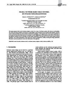
SOLAR PUMPING SYSTEMS The photovoltaic system is constituted of a self-piloted asynchronous motor operating a centrifugal load. The unit is fed by solar cells through an inverter. Pumping without intermediate power storage enabled us to have a simpler photovoltaic system, more reliable; maintenance-fee is less expensive than a system with battery [5]. The system to be investigated is an immersed centrifugal motor-pump SP5A7 (nominal speed 2860rpm for an industrial frequency equalizes with 50Hz). Figure 1 shows the block diagram of a closed loop field-oriented controlled (FOC) induction motor drive incorporating the proposed ANN-based MPPT controller. The command voltage , is generated from the frequency or speed command (irradiance G and temperature Ta dependents).
Figure 1. Field-oriented control of induction motor showing neural network based implementation
2.1. Photovoltaic array model Some authors have proposed more sophisticated models that present better accuracy and serve for different purposes. The basic equation from the theory of semiconductors that mathematically describes the I–V characteristic of the PV array, equation (1) describes the single-diode model presented in Figure 2 [6], [7]. I
I sh
ID D
I ph
Ns Ns Np
Rsh
Np
Rs
V
Figure 2. Single-diode model of the theoretical PV cell and equivalent circuit of a practical PV device including the series and parallel resistances (1) 1
exp
(2)
∆
1
(3)
(4) When: (5) IJPEDS Vol. 4, No. 2, June 2014 : 241 – 255
IJPEDS
ISSN: 2088-8694
243
(6) and are the photovoltaic (PV) and saturation currents, respectively, of the array and Where cells connected in series per module. is the equivalent series resistance of the array and is the equivalent parallel resistance. Modules connected in parallel increase the current and modules connected in and are the number of modules connected in series and in series provide greater output voltages. parallel respectively of the entire array. e is the electron charge 1.6 ∙ 10 C , is the Boltzmann constant 1.38 ∙ 10 J/K , Kelvin is the temperature of the p-n junction, and is the diode ideality constant. (7)
25
is the bandgap energy of the semiconductor Where and is the reference temperature.
for the polycrystalline Si at
≅ 1.12
(8)
Then
(9)
∆
(10)
The cell temperature can be determined from ambient temperature and with the help of some standard test information: (11) 2.2. Inverter Model Figure 3 shows a series-connection of single phase inverters. In this asymmetrical multilevel topology, each H-bridge must be fed by an individual DC-voltage and is used to increase the multilevel converter performances, without adding any complexity in the power circuit [8], [9].
a
id1
v
1 d
v
2 d
o
4 'd
3 'd
K
4 d
id 2
K
2 'd
K
2 d
K
K
3 d
K
1 'd
2 d
K
U
1 d
1 d
K
U
Figure 3. Structure asymmetrical 5, 7 or 9 level cascaded inverter 51.9 , 2 , at standard test conditions (STC) 7 Each couple of switches such that: functions ,
,
,
∈ 2
1,2
∙∙
is controlled by a couple of switching
A Neural Network Based MPPT Technique Controller for Photovoltaic Pumping System (Mohammed Yaichi)
244
ISSN: 2088-8694 ,
∈ 0,1 1
(12)
The conversion of the switch commutations in to a voltage is described by a conversion function, such that: ⇒
(13)
1,0,1
The output voltage of each cell is given by: ∙
(14)
, 0,
With the input voltage of each cell. The output voltage of a phase is given by: (15) With: s, s
a, b or c ; d, d 2 1 1
1 2 1
1,2 or 3: represent the number of the phase (leg). 1 1 2
(16)
. is the array input To improve the output voltage for such inverters, many different modulation strategies have been developed. Among these strategies, the SVM (Space Vector Modulation). This technique provide the nearest switching vectors sequence to the reference vector that is depends the modulation index r without involving trigonometric functions and provide the additional advantages of superior harmonic quality. The generalized algorithm being used to determine, for the hexagonal structure, the exact position of the vector of reference (detection of nearest three vectors and duty cycles computation) was developed and studied in detail in [9]. 2.3. Motor Asynchronous Model The mathematical dynamic model of the asynchronous motor is described in [10], [11] by the following equation: (17) With:
;
0
0 0
0 0 0 0
;
0 ;
1
;
;
, , are d, : axes corresponding to the asynchronous reference axes in Park model. , axis stator current, rotor flux and q-axis stator current, rotor flux respectively. , , , and are: stator and rotor main inductances, resistances and mutual inductance respectively. σ dispersion factor, and are the angular speed of the rotating magnetic and electric fields respectively. expressed as follows: The induction motor develops an electromagnetic torque IJPEDS Vol. 4, No. 2, June 2014 : 241 – 255
(18)
IJPEDS
ISSN: 2088-8694
245
is the number of pole pairs. 2.4. Centrifugal Pump Model The variation of the pump’s speed can give us numerous charts Q-H. The use of a centrifugal pump needs a preliminary study of the most important charts that characterize it, where efficiency will be optimum with the total head and the speed envisaged by control the pumped water quantity to a desirable head. In addition, they are related to dimensions, kinds and speed of the pump. The chart of the water quantity-head Q-H (Figure 4) explains the different variations in the head of pumping, according to water quantity which forms bent charts. The code then proceeds to the generation of the entire curve. Successively, the program generates a series of characteristics for a fixed range of shaft rotational speeds (generally 35–56 Hz), related to the same pump. It all is done referring to the affinity laws at variable speed. The affinity laws are valid only under conditions of constant efficiency [1], [12]-[13]. Ω
; ⁄Ω
⁄Ω Ω
;
Ω
⁄Ω
(19)
at
, , , Ω and are the actual volumetric flowrate, head, the pump shaft input Where power, rotational speed respectively and the pump efficiency, whereas , , ,Ω and are the same variables referred to the design speed. Once the characteristic and power demand curves are defined, the pump efficiency may be calculated as follows: (20) Where, ∙
(21)
∙
is the power output in terms of pumped water [kW] (i.e. hydraulic output power), ∙ : 9.81 ∙ the constant of gravity, 10 ∙ water volumic mass the constant and is the load constant.
Figure 4.
Characteristic
Using the relations (19) and the pump datasheet, a set of curves giving the flow versus the head and parameterized by speed can be then obtained, but this procedure is large and in order to use these results during calculations this set of points should be fitted to obtain an algebraic equation, this is done by the use of a two-variables third order polynomial function in order to achieve the best possible regression coefficient [13]: , ∙
∙ ∙
∙
∙
∙
∙
∙
∙
∙
∙
∙ (22)
A Neural Network Based MPPT Technique Controller for Photovoltaic Pumping System (Mohammed Yaichi)
246
ISSN: 2088-8694
For the determination of the pump operating point it is required to know both the pump and pipeline characteristics. The piping system deals with the total head that must be overcome by the pump. The Q-H characteristic of the pipe network is given as a function of the geodetic head and head losses (as function of the flow-rate) [14]. Thus, it should at least equal the head corresponding the flow computed by the pump flow-head equation. It comes: (23) The constant
relates to the bead loss caused by fluid friction.
: Geodetic head.
2.5. Vectorial Command Approach The vector control is based on the field-oriented control (FOC) method. For the regulation of the main variables (current, flux, speed) to their reference values, regulators were used of the type PI [10], [11]. So we have as interest to keep only the axis flux component, and that means to oblige the axis flux component to be zero. 0 and
(24)
The flux and torque will be reduced respectively then to: (25) Therefore the
(26)
I and
axis statoric voltages equations will be:
(27)
The compensation has as objective to uncouple the two and axis voltages and currents. Under such conditions, the system becomes linear like in case of DC motor. Thus we have: (28) Where, (29) (30) Are the compensation voltages. The transfer functions of the plant for the controllers of the vector-controlled induction motor drives can be derived as shown in [10], [11]. and current controllers: Speed,
(31)
Where is the Laplace operator. IJPEDS Vol. 4, No. 2, June 2014 : 241 – 255
IJPEDS
ISSN: 2088-8694
247
Based on those equations and after some algebra (Imposition of the poles method) we obtain PI parameters for speed and current (Table 1), were J is the rotor inertia moment, is the viscosity coefficient of the induction motor. After is obtained upon calculation of the transfer function of a closed loop, and are identified from imposition of the poles method. A wise choice the and was parameters made by changing the value of . Table 1. PI Regulator Coefficients Coefficients Current Speed ω
3.
LOCATION OF MAXIMUM POWER POINT At the maximum power point we have: ∙
0⇒
(32)
0
With the current described by equation (01), the voltage may be expressed as:
∆
(33)
Back substitution of the partial derivative of and
for
_
with respect to
and using
_
for
gives: ∆
1
With
(34)
0
_
_
∆
_
and _ the voltage and current at maximum power. Numerical method is applied to solve for _ using an initial guess given by:
_
1
,
or
∆
∆
,
(35)
We obtain a relation linear which can be expressed by: _
0.9325
(36)
0.0142
is found, may be calculated using equation (33) and thus the current and voltage Once _ _ at the maximum power point is determined as a consequence the maximum power. 0.94
_
.
.
∆
1 .
∆ ∆
1
(37)
At optimal regime, for calculation the speed reference, the assessment of power of asynchronous motor is given by: A Neural Network Based MPPT Technique Controller for Photovoltaic Pumping System (Mohammed Yaichi)
248
ISSN: 2088-8694 3
_
_
(38)
_
The relations governing the operation of the motor-pump [15]. (39) ∙
(40)
∙
≅
(41)
∙
(42) By substituting equations
and
into Equation (41). (43)
∙
(44)
∙ Thus the relations (41) then (38) becomes: ∙
(45)
∙ ∙
_
(46)
By rearranging the Equation (45) gives: (47)
0 With, , 0.94
1 .
.
∆
∆ .
∆
1
. By solving the Equation (47), For each value of radiation and the temperature, i.e. the value of its roots, give the speed of instruction corresponding to the optimal operation of the generator PV. In addition, this speed depends on the radiation and the ambient temperature. Results examples are summarized in Figure 7 (red stars).
4.
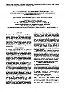
NEURAL NETWORK BASED MPPT The ANN theory, in general, has been well-discussed in the literature [16]-[18], and a number of authors [3], [4], [19] have described its operation in the PV system and for speed control of an induction motor. Neural network architecture is specified through finding the appropriate solution for the non-linear and complex systems or the random variable ones. Among its types, the more widespread, important and useful back propagation network. The function and results of an artificial neural network are determined by its architecture that has different kinds. The simpler architecture contains three layers as shown in Figure 6. The input layer receives the extern data. The second layer, hidden layer, contains several hidden neurons which receive data from the input layer and send them to the third layer, output layer. This later responds to the system. IJPEDS Vol. 4, No. 2, June 2014 : 241 – 255
IJPEDS
ISSN: 2088-8694
249
We can conclude unlimited neural network architectures. The more several hidden layers and neurons in each layer are added; the more complex they become. The network is fully connected which a bias signal is coupled to all neurons in the hidden layer through a weight . The realization of the back propagation network is based on two main points: learning and knowledge. This research was applied by the use of sigmoid function as an activation function in order to calculate the hidden layer output and the linear function to calculate the output. In our study of the effect of network architecture on learning, we have chosen architecture with one hidden layer. We have changed the number of neurons in hidden layer; this architecture is summarized in Table 2. By 5 neurons in hidden layer, the regression coefficient R-square (R2) increases to 0.9999. Table 2. Effect of number of hidden layers on learning Number of neurons in hidden layer 3 5 8 9 11
R2 0.9984 0.9999 0.9991 0.9989 0.9991
Figure 5 shows the proposed ANN topology, it use multilayer perceptron type network consists of an input layer, one hidden layer and an output layer with sigmoidal type transfer function. The composite network uses two neurons at the input, one for the radiation and the other for the ambient temperature, which is normalized and then pulse neurons in the hidden layer. The output layer has only one neuron for the control DC/AC frequency. The procedure described in the previous section will be utilized to generate training data for ANNbased MPPT.
Figure 5. Neural network topology (2-5-1) for speed generated The outputs are calculated by the following equation: ∑
∙
with:
1 ∙∙ 5
(48) (49)
∑ The update of
∙
(50)
is done according to the rule of delta:
A Neural Network Based MPPT Technique Controller for Photovoltaic Pumping System (Mohammed Yaichi)
250
ISSN: 2088-8694 Δ
and
Where: With
(51)
Δ ,Δ
and Δ
(52)
is the step of training and,
∙
,
∙
,
(53) ∙
(54)
∙
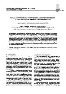
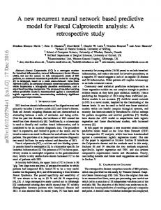
Algorithm architecture of the back propagation implies the following steps as shown in Figure 6. The tests results of ANN-based MPPT at the five operating case (proposed learning examples) were found that the output speed response of the motor-pump with analytical results is higher than the inputs radiation and ambient temperature as shown in Figure 7 (a)-(e) which shows the output of ANN at five case and shows the corresponding data with the analytical results. Also, the MPPT method was validated for the case 37 and compared with the data, they were found to correlate very well (Test of generalization in Figure 8). This means that the network can be operated at any conditions climatic.
Begin 1, : 1: 2:
1 ;∙∙∙∙∙∙∙∙∙; 1 ;∙∙∙∙∙∙∙∙∙; 1 ;∙∙∙∙; And the example given one by one To initialize the weights of the network by random values 0; 2 5 2 ; 3 1 5 0.004, 0.01,
No Yes
End
0,
,
1
calculate the output , , ,
. 53 ,
. 54
∆
. 51
Of the synaptic weights anew
1 1 2
Figure 6. Architecture of the back propagation
IJPEDS Vol. 4, No. 2, June 2014 : 241 – 255
IJPEDS
ISSN: 2088-8694
(a)
(b)
(c)
(d)
251
(e) Figure 7. Test of validation
Figure 8. Test of generalization A Neural Network Based MPPT Technique Controller for Photovoltaic Pumping System (Mohammed Yaichi)
252
ISSN: 2088-8694
5.
RESULTS AND DISCUSSION The Model field-oriented control using MPPT technique is developed and studied in detail in another work [1].
Figure 9. The block diagram of a field-oriented control induction motor coupled to a centrifugal pump, fed by solar cells through an inverter
Figure 10. Behavior of the pump by considering radiation variations Figure 9 gives a diagrammatic sight of a drive at variable speed using the principle of the fieldoriented control. For the simulation results used in this paper, the numerical values for the PV array and the pump SP5A7 are summarized in Table 3-4. The numerical values of the simulation model are obtained either by measurements or identification from laboratory experiments. In order to verify the proposed model, digital simulations were carried out for four insulation level. At the beginning, radiation is worth G=540W/m2, then radiation is brought to G=1200W/m2 in 1s then in G=940W/m2 in 3s and finally, radiation reached G=150W/m2 in 6s.
IJPEDS Vol. 4, No. 2, June 2014 : 241 – 255
IJPEDS
ISSN: 2088-8694
253
Table 3. PV array specifications [7] isofotón Array; : 1.224 9 , : 11.2%, Cell type Peak power Optimal voltage Optimal current Open circuit Voltage Short Circuit current Cell number Temperature Coef iciency of %/ Reference ambient temperature Diode ideality constant Photo current Ω Equivalent series resistance of the panel Equivalent parallel resistance Ω
0.545
PV array: Number of modules connected in series and in parallel
74.4% 75
10% 17.3 4.34 21.6 4.67 36 0.02 20 1.2 4.6756 0.2402 199.4843 0.0047 1.9976 ∙ 10 3.7042 9 Ns × 1 Np
Table 4. Motor-pump specifications [1, 20] Subsystem Pump
Asynchronous motor
Specification N ∙ m ∙ s/rad Type RMS motor voltage V Volt Maximal Courrent I A Speed Ω rms Power P kW Motor frequency fre Hz Stator resistance per phase R Ω Motor power factor cos φ Rotot resistance R Ω Stator leakage inductance L H Rotor leakage inductance L H Mutual Inductance M H Pair pole number p Inertie Torque J kg ∙ m Friction coef icient fr N ∙ m ∙ s/rad Ef iciency η % Flux Q Wb
load Constante k
1.524 ∙ 10 GRUNDFOS MS 402 65∆ 8.5 2860 0.55 50 0.6667 0.8 1.1965 0.0895 0.0895 0.087 1 0.003 2.905 ∙ 10 0.78 0.28 0.3
The response of the system using MPPT controller obtained by simulation is shown in Figure 10. All test results show that the robust tracking speed of induction motor drive with the proposed MPPT control strategy is very effective in tracking the selected tracks at all times, it is observed that, in every case. This controller provides a very useful tool for ensuring optimal efficiency, which essentially keeps its state optimal. On the other hand, the results show the output voltage responses of the PV array to the change of radiation and temperature. For example, at 3s the radiation stepping stepping-down from 1200 to 940W/m2, the PV array voltage stepping-up from 118 to 122volt. This system is able to adapt the operating point according to variations of the radiation and the temperature (random variation). The PI controller brings the measured speed to the desired value smoothly and without the overshoot. We observed the flow estimation and also the resistive torque imposed by the quantity of pumped water. The electromagnetic torque compensates for instantaneously this request of the resistive torque. The figures show that the flow and the couple are decoupled. In addition, flow is constant in permanent mode 0.28 . The statoric voltage by frequency ratio is always kept constant with a / value of 1.3 during operation, the motor is thus, managed by the / constant law, which shows the effectiveness of the loop of speed regulation.
6.
CONCLUSION An optimal operation of a photovoltaic pumping system based on an induction motor was described. A neural network based MPPT has been investigated that operates very well in the PV pumping system. The proposed structure allows at the same time the field oriented control and the maximum power tracking of the photovoltaic array. A Neural Network Based MPPT Technique Controller for Photovoltaic Pumping System (Mohammed Yaichi)
254
ISSN: 2088-8694
This control has given very good results; where it assured a total decoupling between the system parameters. Moreover, it assured a good tracking of the speed with a minimum response time. The regression coefficient R-square (R2) arises in high values through the neural network with one hidden layer, with 5 neurons. The proposed algorithm in neural networks was simulated; the simulation results show that this system is able to adapt the maximum operating point according to variations in external disturbances. In addition, the proposed approach does not need two converters; it uses only a DC/DC converter. Also, increase of both the daily pumped quantity and array PV efficiency are reached by the proposed approach.
REFERENCES [1] M Yaichi, MK Fellah. Centrifugal Motor-Pump System Model intended for the Photovoltaic Pumping applications. Przegląd Elektrotechniczny. 2013; 89: 100-105. [2] D Fiaschi, R Graniglia, G Manfrida. Improving the effectiveness of solar pumping systems by using modular centrifugal pumps with variable rotational speed. Solar Energy. 2005; 79: 234–244. [3] A Saadi, A Moussi. Neural network use in the MPPT of photovoltaic pumping system. Review of renewable energies ICPWE. 2003: 39-45. [4] S Belakehal, H Benalla, A Betounsi. Performance investigation of a solar pumping system using the neural networks MPPT approach. The International Conference on Electrical Engineering and its Applications ICEEA'08. Djillali Liabes University of Sidi-Bel-Abbes, Algeria. 2008. [5] J Royer, T Djiako, E Schiller, BS Sy. Pompage Photovoltaïque. IEPF, University of Ottawa, EIER, CREPA. ISBN 2-89481-006-7, Canada, 1998. [6] MG Villalva, JR Gazoli, ER.Filho. Comprehensive Approach to Modeling and Simulation of Photovoltaic Arrays. IEEE transactions on power electronics. 2009; 24(5). [7] M Yaichi, A Neçaibia, M Sadok. Etude, Caractérisation et Estimation des Paramètres du Module Photovoltaïque Isofotón-75W. 2nd International Conference on Energy and Sustainable Development. University of Adrar and URER/MS, Adrar. 2013. [8] J Song-Manguelle, A Rufer. Asymmetrical Multilevel Inverter for large induction machine drives. International conference for Electrical drives and Power Electronics, EDPE’01, Slovakia. 2001. [9] M Yaichi, MK Fellah, A Neçaibia, A Mammeri. Structure des Onduleurs Multiniveaux Asymétriques Applications aux Systèmes Photovoltaïques. International Conference on Energy and Sustainable Development. University of Adrar, Algeri. 2011. [10] A Meroufel. Commande découplée d’une machine asynchrone sans capteur mécanique. Thesis of doctorate, University of Sidi-Bel-Abbes. 2004. [11] M Makhlouf, F Messai, H Benalla. Vectorial command of induction motor pumping system supplied by a photovoltaic generator. Journal of Electrical Engineering. 2011; 62(1). [12] B Ben Ghanem. Performance of submersible PV water pumping systems in Tunisia. Energy for Sustainable Development. 2012. http://dx.doi.org/10.1016/j.esd.2012.10.003. [13] T Martiré, C Glaize, C Joubert, B Rouvière. A simplified but accurate prevision method for along the sun PV pumping systems. Solar Energy. 2008; 82: 1009-1020. [14] A BETKA. Perspectives for the sake of photovoltaic pumping development in the south. Thesis of doctorate, University of Batna. 2006. [15] MN Mansouri, N Ghanmi, MF Mimouni. Commande et analyse des performances d’une station de pompage photovoltaïque fonctionnant en régime optimal. Revue des énergies renouvelables. 2008 ; 11(1). [16] RS Dhekekar, NV Srikanth. ANN Controlled VSC STATCOM with Harmonic Reduction for VAR Compensation. International Journal of Power Electronics and Drive System (IJPEDS). 2012; 2(1): 76~84. [17] Laxmi Devi Sahu, Satya Prakash Dubey. ANN based Hybrid Active Power Filter for Harmonics Elimination with Distorted Mains. International Journal of Power Electronics and Drive System (IJPEDS). 2012; 2(3): 241~248. [18] Eric Davalo, P Naim. Des réseaux de neurones. Edition EYROLLE. 1993. [19] Ashutosh Mishra, Prashant Choudhary. Artificial Neural Network Based Controller for Speed Control of an Induction Motor using Indirect Vector Control Method. International Journal of Power Electronics and Drive System (IJPEDS). 2012; 2(4): 402~408. [20] M Yaichi, A Mehdaoui, A Mammeri. Research activity report. Research Unit in Renewable Energies in the Saharan Medium URER/MS-Adrar, Algeria. 2012.
IJPEDS Vol. 4, No. 2, June 2014 : 241 – 255
IJPEDS
ISSN: 2088-8694
255
BIOGRAPHIES OF AUTHORS Mohammed Yaichi was born on 1980 in Adrar, Algeria. He received the engineer degree in electrical engineering from the the University of Bechar, Bechar, Algeria, in 2003. And the magister degree from Djillali Liabes University, Sidi-Bel-Abbes, Algeria in 2006. He is currently working toward the doctorate degree in the Power Electronics, and the Photovoltaic Pumping System, Djillali Liabes University of Sidi-Bel-Abbes, Algeria. Since 2009, he is with the Photovoltaic Pumping Team, Research Unit in Renewable Energies in The Saharan Medium (URER/MS) Adrar, Algeria. His research interests include a study on performance improvement of a stand-alone photovoltaic pumping systeme, variable-speed AC motor drives, and different multilevel inverter circuit topologies thus its technique of control PWM.
Mohammed-Karim Fellah was born in Oran, Algeria, in 1963. He received the Eng. degree in Electrical Engineering from University of Sciences and Technology (USTO), Oran, Algeria, in 1986, and The Ph.D. degree from National Polytechnic Institute of Lorraine (Nancy, France) in 1991. Since 1992, he is Professor at the University of Sidi Bel-Abbes (Algeria) and Member of the Intelligent Control and Electrical Power. His current research interest includes Power Electronics, HVDC links, and Drives.
Mammeri Abdelkrim was born on 1979 in Bechar, Algeria. He received the engineer degree in Hydraulic from University of Sciences and Technology (USTO), Oran, Algeria, in 2006, and now studying for master degree. Since 06/11/2006, he is with the Photovoltaic Pumping Team, Research Unit in Renewable Energies in The Saharan Medium (URER/MS) Adrar, Algeria. His research interests include a study on performance improvement of a stand-alone photovoltaic pumping system.
A Neural Network Based MPPT Technique Controller for Photovoltaic Pumping System (Mohammed Yaichi)