International Journal of Electrical and Computer Engineering (IJECE) Vol. 6, No. 4, August 2016, pp. 1421~1433 ISSN: 2088-8708, DOI: 10.11591/ijece.v6i4.9704
1421
A Feed forward Neural Network MPPT Control Strategy Applied to a Modified Cuk Converter Mohamed Tahar Makhloufi, Yassine Abdessemed, Mohamed Salah Khireddine Electronics Department, Batna 2 University, 05000 Algeria
Article Info
ABSTRACT
Article history:
This paper presents an intelligent control strategy that uses a feedforward artificial neural network in order to improve the performance of the MPPT (Maximum Power Point Tracker) photovoltaic (PV) power system based on a modified Cuk converter. The proposed neural network control (NNC) strategy is designed to produce regulated variable DC output voltage. The mathematical model of the Cuk converter is developed and an artificial neural network algorithm is derived. The Cuk converter has some advantages compared to other types of power converters. However the nonlinear characteristic of the Cuk converter due to the required switching technique is difficult to be handled by conventional controller. To overcome this problem, a neural network controller with online learning back propagation algorithm is elaborated. The designed NNC strategy tracks the converter voltage output changes and improves the system dynamic performance regardless of the load disturbances and supply variations. The proposed controller effectiveness during dynamic transient response is then analyzed and verified using MATLAB-Simulink. The simulation results confirm the excellent performance of the proposed NNC technique for the studied PV system.
Received Dec 14, 2014 Revised Jun 8, 2016 Accepted Jun 20, 2016 Keyword: Battery Maximum power point tracker artificial neural network controller Modified Cuk converter photovoltaic system
Copyright © 2016 Institute of Advanced Engineering and Science. All rights reserved.
Corresponding Author: Mohamed Tahar Makhloufi, Electronics Department, Batna University, 05000 Algeria. Email:
[email protected]
1.
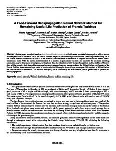
INTRODUCTION In the era of sustainable energy development, photovoltaic (PV) technology [1]-[3] has shown significant potential as a renewable energy source. Our research work focuses on improving performance and efficiency of a PV system through the use of an appropriate algorithm for controlling the power interface. The main objective is to find an effective and optimal strategy [4],[5] for extracting the maximum available power from the PV generator. Moreover, the study, design and simulation of a unit composed of an MPPT control technique and the management of the energy transmitted to the load are carried out. The main parts in out study are: the modeling of a PV system, the topological study of the power interface, the study of maximum power point tracking (MPPT) algorithms, the simulation, the design of the MPPT Cuk [ converter and the PV output voltage regulation. In this investigation, an intelligent control strategy (NNC) [6]-[8] is improved and the problem of local maxima in the power curve of the PV generator occurring during partial shading is processed [4]. The NNC avoids a misinterpretation of the location of the MPP under rapidly changing environmental conditions. In this paper the Cuk converter is used between the PV module panel and the Switch. And the battery is between the charging circuit controller battery and the Switch. The outline of the proposed system is depicted in Figure 1.
Journal homepage: http://iaesjournal.com/online/index.php/IJECE
1422
ISSN: 2088-8708
Cuk Power Converter
PV Module
MPPT Neural Network
Battery Charger
Switch
Load
Battery
Figure 1. Outline of the proposed system
2.
PV ARRAY CHARACTERISTICS An ideal solar cell may be modelled [1] by a current source connected in parallel with a diode; the current source represents the generated photocurrent when the sunlight hits the solar panel, and the diode represents the p-n transition area of the solar cell. In practice no solar cell is ideal and a shunt resistance Rsh and a series resistance Rs component are incorporated in the model according to its behaviour. The basic structure of a PV cell is shown in Figure 2, and the equivalent circuit of a solar cell comprising parasiti resistive components [1],[9] is depicted Figure 3.
Figure 2. Basic structure of a PV cell
From the above electrical equivalent circuit [1],[9] of solar cell shown in Figure 3, it is evident that the voltage across the load resistance R and the current I which is flowing through this load can be written as equation (1) : (1) Where IL light generated current, is the diode current is the current which is shunted through Rsh. The current diverted through the diode is given by equation (2), as follows: (2) Here T is the absolute temperature in Kelvin. q is the charge of a electron, K is the Boltzmann’s constant, n is the diode ideality factor which depends on the certain PV technology and Is is the reverse saturation current in amperes. Substituting these into the equation (1), produces the characteristic Equation (3), of a typical solar cell, this relates solar cell parameters to the output current and voltage.
IJECE Vol. 6, No. 4, August 2016 : 1421 – 1433
IJECE
ISSN: 2088-8708
1423
(3) Sometimes, to simplify the model, the effect of the shunt resistance is not considered, that is Rsh is infinite, so the expression of (3), simplify to as equation (4). (4) A PV panel is composed of many solar cells, which are connected in series and/or parallel so the output current and voltage of the PV panel are high enough for a certain application. Taking into account the simplification of equation (4), the output current-voltage characteristic of a PV panel is expressed by equation (5), where, Np and Ns are the number of solar cells in parallel and series respectively.
Figure 3. Equivalent circuit of a solar cell
The photovoltaic solar modelled with Malab/Simulink is depicted in Figure 4.
Figure 4. Photovoltaic solar modelled with Malab/Simulink
(5) Where is the parallel number of the PV cells, ns is the series number of the PV cells, is the reverse-saturation-current, is the output current of the PV panels, q is the electronic charge, k is Boltzmann’s gas constant, is the cell temperature of the PV panels and A is the ideality factor of the PV panels. The intensity of solar irradiance is the most dominant environmental factor which is strongly affecting the electrical characteristics of solar panel according to the equation (5). The effect of the irradiance on the voltage-current (V-I) and voltage-power (V-P) characteristics [10] of solar panel under various irradiance levels is depicted in Figure 5. From this figure it is clear that under higher irradiance, the PV cell produces higher output currents because the light generated current is proportionally generated by the flux of photons. The maximum power point (MPP) decreases with decreasing irradiance and this is indicated on each (V-P) curve in Figure 6.
3.
MAXIMUM POWER POINT TRACKING (MPPT) Usually there are two major approaches adopted for maximizing power extraction from PV sources. First one is the mechanical tracking of the solar panel. In this case the panel is attempted to position in any terrain at an angle of ninety degree with the direction incoming ray of sun. A Feed forward Neural Network MPPT Control Strategy Applied to a .... (Mohamed Tahar Makhloufi)
1424
ISSN: 2088-8708
Figure 5. Characteristic curves current of solar panel, at different irradiance levels and 25°C
Figure 6. Characteristic curves power of solar panel, at different irradiance levels and 25 °C
This issue is beyond our topic of discussion. The second one is the electrical MPPT where electrical operating point is forced at the peak power point continuously by adjusting the duty cycle of the DC-DC converter inserted between PV array and load. The methods vary in complexity, sensors required, tracking efficiency, convergence speed, cost, and in other respects. Some of the well-known techniques are Perturb& Observe (P&O) [2],[4], Incremental Conductance [10],[11], Fractional Open-Circuit, Fractional ShortCircuit, Fuzzy Logic [6] and Neural Network [7],[8],[12],[13]. Both perturb and observe, and incremental conductance, are examples of "hill climbing" methods that can find the local maximum of the power curve for the operating condition of the PV array, and so provide a true maximum power point. The perturb and observe method can produce oscillations of power output around the maximum power point even under steady state irradiance. The incremental conductance method has the advantage over the perturb and observe (P&O) method that it can determine the maximum power point without oscillating around this value [11]. It can perform maximum power point tracking under rapidly varying irradiation conditions with higher accuracy than the perturb and observe method. However, the incremental conductance method can produce oscillations and can perform erratically under rapidly changing atmospheric conditions. The computational time is increased due to slowing down of the sampling frequency resulting from the higher complexity of the algorithm compared to the P&O method [2],[4],[14]. The MLP neural method [8] is based on the estimation of the optimised value [5] of the duty cycle for transmitting the maximum power produced by the solar panel, green charge. The power efficiency of this system in this case is maximum. The point of maximum power in this case is determined accurately regardless of the fast varying external conditions such as solar radiation or panel temperature
4.
THE MODIFIED CUK POWER CONVERTER The Cuk converter [15]-[18] is a type of step-down/step-up converter [9], [19] based on a switching boost buck topology. Essentially, the converter is composed of two sections, an input stage and an output stage. The basic schematic of the Cuk converter is presented in Figure 7, where Vin is an input voltage source; V0 is the output voltage; L1 is an input inductor and the MOSFET S is a controllable switch. C1 is an energy transfer capacitor, D1 is a diode, C0 and L0 are respectively a filter capacitor and inductor. The resistance R is the load. An important advantage of this topology is a continuous current at both the input and the output of the converter. The disadvantages of the Cuk converter are the high number of reactive components and the high current stresses on the switch S, the diode D1, and the capacitor C0.
Figure 7. Cuk converter
IJECE Vol. 6, No. 4, August 2016 : 1421 – 1433
IJECE
ISSN: 2088-8708
1425
During mode 1 (Figure 8), the input voltage is applied when the MOSFET switch transistor S is closed then the current through the inductor L1 rises. At the same time the voltage of capacitor C1 reverse biases diode D1 and turns it off. The capacitor C1 discharges its energy to the circuit formed by C1, C0, L0 and the load R.
Figure 8. Cuk converter on state
During mode 2, the input voltage is applied and the switch S is open, then the diode D1 is forward biased and the capacitor C1 is charged through L1 .The energy which is stored in the inductor L0 is transferred to the load. Thus, the diode D1 and the switch S provide a synchronous converter switching action (Figure 9).
Figure 9. Cuk converter in the off-state
The relations between output and input currents and voltages are given in the following: (6) (7) Thus the ration of the input and output voltages for the buck-boost converter is the same as the ratio of the input and output currents for the Cuk converter. The advantage of the modified Cuk converter [16] is that the input and output inductors create a smooth current at both sides of the converter while the buck, boost and buck-boost have at least one side with pulsed current. The simulation model with Matlab/Simulink of the overall Cuk converter bases PV system is presented in Figure 10.
Figure 10. Matlab/Simulink simulation model of the Cuk converter
A Feed forward Neural Network MPPT Control Strategy Applied to a .... (Mohamed Tahar Makhloufi)
1426
ISSN: 2088-8708
5.
BATTERY MATHEMATICAL MODEL Battery model can usually be divided into experimental model, electrochemical model and equivalent circuit model. The equivalent circuit model is most suitable for dynamic simulation. Based on shephred battery model, reference presents a generic battery model for dynamic simulation, which assumes that the battery is composed of a controlled-voltage source and a series resistance, shown as Figure 11. This generic battery model considers the state of charge (SOC) as the only state variable.
Figure 11. A generic battery model
The expression of the controlled voltage source is: (8) Where, Eb is no-load voltage (V); E0 is battery constant voltage (V); K is polarization voltage (V); Q is battery capacity (Ah); A is exponential zone amplitude (V); B is exponential zone time constant inverse (Ah-1)。 . This model assumes the internal resistance of the battery is kept constant during both charge and discharge pahes. All parameters are deduced from the discharge and assumed to be same for charge. Figure 12 is discharge characteristics of the battery at rated discharge current, and all parameters can be calculated by three points marked in the figure, namely fully charged voltage (Efull), the end of exponential zone (Eexp, Qexp), the end of nominal zone (Enom, Qnom).
Efull
Eexp , Qexp
Enom , Qnom
Figure 12. Discharge characteristics curve of the battery at the rated discharge current (V-Q)
Use MATLAB/Simulink to model the battery, as shown in Figure 13. The battery discharge curves at different discharge currents are obtained, shown in Figure 14.
Figure 13. The battery model in MALTAB/Simulink
IJECE Vol. 6, No. 4, August 2016 : 1421 – 1433
Figure 14. Discharge characteristics curves of the battery at different discharge current (V-Q)
IJECE
ISSN: 2088-8708
1427
6.
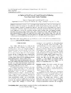
DESCRIPTION OF THE PROPOSED TECHNIQUE The MPPT strategy proposed here consists of a combination of a neural network and P&O techniques for the implementation of the duty cycle regulator. When solar radiation changes slowly, the system controls the DC-DC converter using the P&O, and the neural network learns simultaneously the MPP found by the P&O [2]. However if the solar radiation varies too rapidly [4], the neural network controller tracks the MPP rapidly and adjusts the duty cycle of the DC-DC converter [1]. Neural networks usually require independent and identically distributed samples to ensure successful on-line learning. Here, however, similar training samples are used by the artificial neural network (ANN). The architecture of the ANN used is of the multi-layer perceptron (MLP) type. The main idea of the learning algorithm is that the neural network learns each sample online because it is difficult to store all learning samples in small devices. In Figure 15, the ANN learning technique is a memory-based one and allows to estimate at any instant the required optimal duty cycle ’D’ [1]. Even with sparse data in a multidimensional measurement space, the algorithm provides smooth transitions from one estimated value of D to another. The ANN consists of an input layer (Ppv), two hidden layers with respectively five neurons and two neurones and an output layer which consists of one neurone which has the output the converter duty ratio D shown in the following figure:
Performance is 1.74171e-024, Goal is 0
-5
10
D
-10
Training-Blue
Ppv
10
-15
10
-20
10
0
1
2
3
4 8 Epochs
5
6
7
8
Figure 15. Training error using the neural network MLP
7.
RESULTS AND ANALYSIS Figure 16 shows the PV simulation system under MATLAB/Simulink/Simpower Systems in order to validate the on-line learning ANN, adequate simulations tests have been implemented and carried out.
Figure 16. Simulation system in MATLAB/Simulink
Based on the above models and control methods, the grid-connected hybrid PV/Battery generation system can be implemented in MATLAB/Simulink, as shown in Figure 16. In this study, three simulation cases are considered, namely: a. Simulation in standard normal environmental conditions; b. Simulation with the occurance of two different disturbances; c. Simulation with constant step changes of the PV solar radiation. A Feed forward Neural Network MPPT Control Strategy Applied to a .... (Mohamed Tahar Makhloufi)
1428
ISSN: 2088-8708
7.1. Operation in Standard Environmental Conditions The Figures 17, 18 and 19 below allow us to visualize the output PV panel current, voltage and power using the ANN controllers in standard atmospheric conditions (1000W/m2, 25°C). The next following Figures 20, 21 and 22 show the Cuk converter [1] output current, voltage and power using the ANN controllers in standard atmospheric conditions : we have obtained a training error of about 1.0e-19.The output battery voltage during the charging period is presented in Figure 23. The corresponding state of charge of the battery is presented in Figure 24.
Ipv
Vpv
10
110 100
8 90 6 Voltage(V)
Current(A)
80 4
70 60
2 50 0 40 -2
0
0.01
0.02
0.03
0.04
0.05 0.06 Time(sec
0.07
0.08
0.09
30
0.1
0
Figure 17. The output PV panel current
0.01
0.02
0.03
0.04
0.05 0.06 Time(sec)
0.07
0.08
0.09
0.1
Figure 18. The output PV panel voltage
Pout
Ppv
450
700
400
600
350 500
300 Power(W)
Power(W)
400 300
250 200
200
150 100
100
0 -100
50
0
0.01
0.02
0.03
0.04
0.05 0.06 Time(sec)
0.07
0.08
0.09
0
0.1
0
0.01
0.02
0.03
0.04
0.05 0.06 Time(sec)
0.07
0.08
0.09
Figure 22. The Cuk converter output power with The ANN controller
Figure 19. The output PV panel power
Iout
Vbat
8
47.1986
7 47.1986
6
47.1986 Voltae(V)
Current(A)
5 4 3 2
47.1986
47.1986
1 47.1986
0 -1
0
0.01
0.02
0.03
0.04
0.05 0.06 Time(sec)
0.07
0.08
0.09
0.1
Figure 20. The Cuk converter output current with ANN controller
IJECE Vol. 6, No. 4, August 2016 : 1421 – 1433
0.1
47.1986
0
2
4
6 Time(sec)
8
10
12 x 10
4
Figure 23. The output battery voltage during charging Period
IJECE
ISSN: 2088-8708 Vout
1429
State of charge
60
2 1.8
50
1.6 1.4 1.2
30 SOC
Voltage(V)
40
1
20 0.8 0.6
10
0.4
0 0.2
-10
0
0.01
0.02
0.03
0.04
0.05 0.06 Time(sec)
0.07
0.08
0.09
0
0.1
Figure 21. The Cuk converter output voltage with The ANN controller
0
2
4
6 Time(sec)
8
10
12 x 10
4
Figure 24. The state of charge of battery with ANN controller
7.2. Simulation with Disturbances In Figures 25-31, two different disturbances are assumed as input in the irradiance of PV panel (using signal builder bloc of simulink). The first one ‘d1’correponds to a sudden step increase of 1000W/m2 in the solar radiation which occurs at 0.028s and the second one ‘d2‘ is a sudden step decrease of 1000W/m2 which happens at 0.068s. The ANN controller adjusts the duty cycle of the Cuk converter to produce maximum power to charge the battery. The response time of the system at the start is short about 10ms, while it is about 60ms for other systems [3]. The output load voltage during the bus/battery commutation is presented in Figure 32.
Ipv
Vout
10
60
50
8
40
Voltage(V)
Current(A)
6
4
30
20
d1
2 10
d1
0
-2
0
0.01
0.02
d2 0.03
0.04
0.05 0.06 Time(sec)
0.07
0.08
0.09
d2
0
-10
0.1
Figure 25. The output PV panel current with the with the occurance of the two disturbances
0
0.01
0.02
0.03
0.04
0.05 0.06 Time(sec)
0.07
0.08
0.09
0.1
Figure 29. The Cuk converter output voltage occurance of two solar irradiance disturbances
V pv
Vbat
110
47.1986
100 47.1986
90
d1
d2
47.1986 Voltae(V)
Voltage(V)
80 70
d2
d1
47.1986
60 47.1986
50 47.1986
40 30
0
0.01
0.02
0.03
0.04
0.05 0.06 Tim (sec)
0.07
0.08
0.09
0.1
Figure 26. The output PV panel voltage with the occurance of two solar irradiance disturbances
47.1986
0
2
4
6 Tim e(s ec )
8
10
12 x 10
4
Figure 30. The output battery voltage with two disturbances during the Charging Period
A Feed forward Neural Network MPPT Control Strategy Applied to a .... (Mohamed Tahar Makhloufi)
1430
ISSN: 2088-8708 P pv
P out
700
450 400
600
d2
d1
500
350 300 Power(W)
Power(W)
400 300
250 200
200 150
100
-100
d1
100
0
d2
50
0
0.01
0.02
0.03
0.04
0.05 0.06 Tim e(s ec )
0.07
0.08
0.09
0
0.1
0
Figure 27. The output PV panel power with the occurance of the two disturbances
0.01
0.02
0.03
0.04
0.05 0.06 Tim e(sec)
0.07
0.08
0.09
0.1
Figure 31. The Cuk converter output power with two disturbances
Iout
Vbus
8
60
7 50
6 40 Voltage(V)
Current(A)
5 4 3 2
d1
1
30
20
d2
Bus/Battery Commutation
10
0 -1
0
0.01
0.02
0.03
0.04
0.05 0.06 Time(s ec )
0.07
0.08
0.09
0
0.1
Figure 28. The Cuk converter output current with the occurance of the two disturbances
0
0.05
0.1
0.15
0.2 Time(sec)
0.25
0.3
0.35
0.4
Figure 32. The output load voltage during the bus/battery commutation
7.3. Simulation with Rapid Step Changes of Solar Radiance Moreover, in order to prove the efficiency of the ANN-MPPT on-line controller, we have simulated in Figures 33-40 a continuous step increases of solar radiation. The ANN controller shows that it tracks conveniently the maximum power point, in order to avoid having to move rapidly the operation point when the solar radiation is varying quickly or when a disturbance or data reading error occurrence [1]. The figures above mentioned show that the MPP control tracks the charging of the back-up battery quickly when the shading of the PV panel changes considerably and quickly. It can be seen that a high control precision and stability in charging from the state of charge of the battery as depicted in Figure 40, are obtained.
Ipv
Vout
6
40 35
5
30
4
Voltage(V)
Current(A)
25
3
2
20 15 10
1 5
0 0
-1
0
0.01
0.02
0.03
0.04
0.05 0.06 Tim e(sec)
0.07
0.08
0.09
0.1
Figure 33. The output PV panel current with a step change of irradiance
IJECE Vol. 6, No. 4, August 2016 : 1421 – 1433
-5
0
0.01
0.02
0.03
0.04
0.05 0.06 Time(s ec)
0.07
0.08
0.09
0.1
Figure 37. The Cuk converter output voltage with a step change of irradiance
IJECE
ISSN: 2088-8708
1431
V pv 70 P out 250
60 200
40
150
Power(W)
Voltage(V)
50
30
100
20 50
10
0
0
0.01
0.02
0.03
0.04
0.05 0.06 Time(s ec )
0.07
0.08
0.09
0
0.1
Figure 34. The output PV panel voltage with a step change of irradiance
0
0.01
0.02
0.03
0.04
0.05 0.06 Tim e(s ec )
0.07
0.08
0.09
0.1
Figure 38. The Cuk converter output power with a step change of irradiance
V bat
P pv 300
47.1986
250
47.1986
200
Voltage(V)
47.1986 Power(W)
150
100
47.1986
47.1986 50
47.1986
0
-50
0
0.01
0.02
0.03
0.04
0.05 0.06 Tim e(sec)
0.07
0.08
0.09
47.1986
0.1
Figure 35. The output PV panel power with a step change of irradiance
0
2
4
10
12 x 10
4
State of charge
6
1
5
1
4
1
3
1 SOC
Curren(A)
8
Figure 39. The output battery voltage with a step change of irradiance during the Charging Period
Iout
2
1
1
1
0
1
-1
0
0.01
0.02
0.03
0.04
0.05 0.06 Tim e(s ec )
0.07
0.08
0.09
0.1
Figure 36. The Cuk converter output current with a step change of irradiance
8.
6 Time(sec )
1
0
2
4
6 Time(sec)
8
10
12 x 10
4
Figure 40. Variation of the battery state of charge (SOC)
CONCLUSION In this research work, an intelligent MPPT technique is presented to the control of a Cuk DC-DC converter. The on-line ANN controller using the back-propagation algorithm in order to minimize the controlled error, in conjunction with the well-known P&O technique [18], has been utilized for reference voltage estimation in the feed-forward loop. The MATLAB/Simulink software has been used for the simulation of the power and control circuits. This improved MPPT algorithm extracts the maximum power point from the PV panel module. The simulation results concerning major and minor disturbances of solar radiation showed that the system response deduced from the plotted output voltage simulation waveforms is within satisfactory response times (less than 30 ms). Moreover, the overall system power efficiency [16] obtained of the developed technique is about 97.5% and hence it is much better than other ANN based PV systems MPPT techniques which does not exceed 95% [7],[8],[12]. Thus the proposed control method is more effective than other previous techniques [5],[20]. This strategy has several advantages, particularly in that there is no need for PV panel output voltage and current sensors, and hence it avoids a complex calculation of the PV output power. Also, the maximum output power of the system stand-by battery is obtained when sudden solar radiation changes of the PV panel occur and there is a continuous impedance matching of the PV source and the system battery-load [5]. Other hybrid techniques using evolutionnary algorithms for instance the particule swarm (PSO) and the ANN strategies y could be used for further enhancement of the MPP tracking of stand-alone PV systems [13],[20]. A Feed forward Neural Network MPPT Control Strategy Applied to a .... (Mohamed Tahar Makhloufi)
1432
ISSN: 2088-8708
REFERENCES [1] [2] [3] [4] [5]
[6] [7] [8] [9]
[10]
[11]
[12] [13] [14]
[15] [16] [17] [18] [19] [20]
Sridhar R., et al., “Modeling of PV Array and Performance Enhancement by MPPT Algorithm,” International Journal of Computer Applications, vol/issue: 7(5), pp. 0975 –8887, 2010. Fermia N., et al., “Predictive & adaptive MPPT perturb and observe method,” IEEE Trans. Aerospace and Electronics Systems, vol. 43, pp. 934-950, 2007. Stallon S. D., et al., “High Efficient Module of Boost Converter in PV Module,” International Journal of Electrical and Computer Engineering (IJECE), vol/issue: 2(6), pp. 758-781, 2012. Sera D., et al., “Optimized Maximum Power Point Tracker for Fast- Changing Environmental Conditions, Industrial Electronics,” IEEE Transactions on., vol/issue: 55(7), pp. 2629 – 2637, 2008. Eduardo I. and Rivera O., “Maximum Power Point Tracking using the Optimal Duty Ratio for DC-DC Converters and Load Matching in Photovoltaic Applications,” IEEE Xplore Applied Power Electronics Conference, pp. 987991, 2008. Chang Y. H. and Chang C. Y., “A Maximum Power Point Tracking of PV System by Scaling Fuzzy Control,” International Multi-Conference of Engineers and Computer Scientists, pp. 623-629, 2010. Makhloufi M. T., et al., “Maximum Power Point Tracker for Photovoltaic Systems using On-line Learning Neural Networks,” International Journal of Computer Applications, vol/issue: 72(10), pp. 29-36, 2013. Hiyama T. S. and Imakubo T., “Evaluation of neural network based real time maximum power tracking controller for PV system,” IEEE Trans. Energy Conversion, vol. 10, pp. 543-548, 1995. Subramanya B. and Nagaraja H. N., “Effect of Parasitic Elements on the Performance of Buck-Boost Converter for PV Systems,” International Journal of Electrical and Computer Engineering (IJECE), vol/issue: 4(6), pp. 831-836, 2014. Divya T. R. C. and Raghavendar I., “Implementation of Incremental Conductance MPPT with Direct Control Method Using Cuk Converter,” International Journal of Modern Engineering research (IJMER), vol. 2, pp. 44914496, 2012. Safari A. and Mekhilef S., “Simulation and Hardware Implementation of Incremental Conductance MPPT with Direct Control Method Using Cuk Converter,” Industrial Electronics, IEEE Transactions, vol/issue: 58(4), pp. 1154-1161, 2011. Vasarevicius D., et al., “Application of Artificial Neural Networks for Maximum Power Point Tracking of Photovoltaic Panels,” Electronika ir electrotehechnika, vol/issue: 18(10), pp. 1392-1215, 2012. Makhloufi M. T., et al., “Tracking Power Photovoltaic System using Artificial Neural Network Control Strategy,” International Journal of Intelligent Systems and Applications (IJISA), vol/issue: 6(12), pp. 17-26, 2014. Adel A. E., et al., “A modified perturb and observe algorithm for maximum power point tracking of photovoltaic system using Buck-Boost converter,” Journal of Engineering Sciences Assiut University Faculty of Engineering, Vol/issue: 43(3), pp. 344-362, 2015. Ramyaka S., et al., “Simulink Model of PV array with MPPT using Cuk converter,” International Journal of Scientific & Engineering Research, vol/issue: 6(2), 2015. Abbas A. F., et al., “New efficient Bridgeless Cuk Converter for PFC application,” IEEE Transactions on Power Electronics, vol/issue: 27(7), 2012. Syam M. S. and Kailas T. S., “Grid Connected PV System using Cuk Converter,” International Conference on Microelectronics, Communication and Renewable Energy ICMiCR, 2013. Nagarajan G. and Nalinkant M., “Simulation of Fuzzy logic Controller of MPPT Using Cuk Converter Application to PV cell,” Int.J. of Intelligent Computing and Applied Sciences, vol/issue: 1(2), 2013. Lakpathi G., et al., “An Effective High Step-Up Interleaved DC-DC Converter Photovoltaic Grid Connection System,” International Journal of Soft Computing and Engineering (IJSCE), vol/issue: 3(4), pp. 2231-2307, 2013. Emad M. and Masahito S., “Variable Step Size Maximum Power Point Tracker Using a Single Variable for Standalone Battery Storage PV Systems,” Journal of Power Electronics, vol/issue: 11(2), pp. 221-228, 2011.
BIOGRAPHIES OF AUTHORS
Mohamed Tahar Makhloufi was born on February 06, 1961. He received the B.Sc. and M.Sc. degrees in Electronics from the University of Batna, Algeria, in 1986 and 2000, and the Doctorat in Science Degree in 2014 respectively. He is now teaching as a lecturer in Power Electronics and Control at the Department of Electronics, Faculty of Engineering, and University of Batna. He has been a member of staff of Laboratory of Advanced Electronics (LEA) from 2002. He is a member of many research projects if Power electronics and control such as the applications of solar energy in autonomous vehicles and residential power supplies in remote areas. He has published six international papers in photovoltaic energy conversion and control using modern control techniques. His research interests include power resonant converters, control using artificial intelligence strategies and their applications in various technical devices such as robots and artificial satellites. e-mail :
[email protected]
IJECE Vol. 6, No. 4, August 2016 : 1421 – 1433
IJECE
ISSN: 2088-8708
1433
Yassine Abdessemed was born on January, 28th 1959 at Batna, Algeria. He carried out undergraduated studies at the university of Constantine, Algeria from 1978 till 1980 and has obtained the degree of bachelor of engineering from the university of Algiers-ENPA-Algiers, Algeria in June 1983. From 1985 till 1990 he carried out post- graduated and research studies in power electronics and real-time control of variable speed AC electrical drives. He was awarded the Ph.D degree from the department of electrical engineering of the University of Bristol, Great-Britain, in January 1991. He has been associate lecturer during five years at the electrical department, Faculty of Engineering of Bristol. He received a postdoctoral degree in Research Habilitation (HDR) of conducting research in robotics control from Batna University in 2007 where he is presently a lecturer and research member in the Productic Research Laboratory (LRP). He is now an associate professor in applied electronics, power electronics and control at the Department of Electronics of Batna. He is currently supervising many postgraduate students in different areas of applied power electronics, intelligent control and robotics. He has published seven international journal papers in solar photovoltaic energy control, mobile robots real-time control, data fusion for the mobile robots localization, fault diagnosis and fault tolerant control of remotely operated robot arms. His main research interests are power electronics applications in general and the neuro-fuzzy logic control techniques applied to solar energy and mobile manipulator robots. e-mail :
[email protected]
Mohamed Salah Khireddine was born at Tolga (Algeria) in 1956. He obtained the Informatics Engineer Degree from the University of Algiers in 1980. He received his Doctorate (Ph.D) in Automation and computer science from the University of Aix-Marseille (France) in July 1990. In 2010 he received a postdoctoral degree in “Habilitation of conducting research in Control Engineering” from the Batna University where he is currently Associate professor in Automation and Industrial Computing and research member in the Advanced Electronics Laboratory (LEA) and head of artificial intelligence team in Productics Research Laboratory (LRP). He is currently supervising many doctor’s and master’s thesis in different areas of power electronics and robotics. He has published ten papers in the real-time control of mobile robots, fault diagnosis and fault tolerant control of robot arms, and solar photovoltaic energy control. His research interests include Faults Diagnosis, Fault Tolerant Control, Artificial Intelligence, Control Systems and Robotics. e-mail :
[email protected]
A Feed forward Neural Network MPPT Control Strategy Applied to a .... (Mohamed Tahar Makhloufi)