digital converter using Co-ordinate Rotation Digital Computer CORDIC algorithm. ... algorithm in radar pulse compression, rotary encoders, and waveform ...
PIERS Proceedings, Guangzhou, China, August 25–28, 2014
50
A New FPGA Prototype for Synchro to Digital Converter Using CORDIC Algorithm Mohamed Rizk, Ahmed Hossin, and Alaa El-Din Sayed Hafez Faculty of Engineering, Alexandria University, Alexandria, Egypt
Abstract— This paper introduce a new approach to FPGA implementation of synchro to digital converter using Co-ordinate Rotation Digital Computer CORDIC algorithm. This algorithm was the best replacement of analog conversion system by the high resolution digital. CORDIC algorithm used for the fast calculation of elementary functions like multiplication, division, trigonometric functions. The approach is based on receiving the synchro signals S1 , S2 , and S3 from the synchro motor, and converts them to two perpendicular signals sin signal and cosine signal using solid state Scott-t transformer. Then the a CORDIC circuit receive this signals after converting them to digital and produce the azimuth angle in digital format. This prototype of hardware implementation of CORDIC algorithm used Spartan-III series FPGA, with constraint to area efficiency and throughput architecture. The prototype results show that the conversion time is less than 1 µs which is suitable for real time applications in radar and missile control applications. 1. INTRODUCTION
CORDIC is the abbreviation of Co-ordinate Rotation Digital Computer. The first description for iterative approach of this algorithm is firstly provided by Jack E. Volder in 1959 [1]. CORDIC algorithm provides an efficient way of rotating the vectors in a plane by simple shift add operation to estimate the basic elementary functions like trigonometric operations, multiplication, division and some other operations like logarithmic functions, square roots and exponential functions. Most of the applications either in wireless communication or in digital signal processing are based on microprocessors which make use of a single instruction and a bunch of addressing modes for their working. As these processors are costs efficient and offer extreme flexibility but yet are not suited for some of these applications. During the last 50 years the CORDIC algorithm has emerged in a wide variety of applications. The CORDIC algorithm has received increased attention after a unified approach is proposed for its implementation [2]. The CORDIC arithmetic processor chip is designed and implemented to perform various functions possible in rotation and vectoring mode of circular, linear, and hyperbolic coordinate systems [3]. Since then, CORDIC technique has been used in many applications [4], such as single chip CORDIC processor for DSP applications [5, 6]. Recently several researches applied CORDIC algorithm in radar pulse compression, rotary encoders, and waveform generation [7–12]. This paper implement CORDIC S/D converter to convert synchro signals into high resolution digital azimuth angle. This achieves a high precision S/D conversion with low propagation delay compared with that implemented using microcontroller or analog processing. 2. CORDIC ALGORITHM
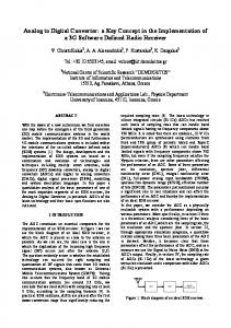
The CORDIC algorithm involves rotation of a vector v on the XY -plane in circular, linear and hyperbolic coordinate systems depending on the function to be evaluated. The CORDIC algorithm performs a planar rotation. Graphically, planar rotation means transforming a vector (Xi , Yi ) into a new vector (Xj , Yj ) [13, 14]. Y
(Xj, Yj)
θ
(Xi, Yi) X
Figure 1: Rotating the vector.
Using a matrix form, a planar rotation for a vector of (Xi , Yi ) is defined as · ¸ · ¸· ¸ Xj cos θ − sin θ Xi = Yj sin θ cos θ Yi
(1)
Progress In Electromagnetics Research Symposium Proceedings, Guangzhou, China, Aug. 25–28, 2014
51
The θ angle rotation can be executed in several steps, using an iterative process. Each step completes a small part of the rotation. Many steps will compose one planar rotation. A single step is defined by the following equation: · ¸ · ¸· ¸ Xn+1 cos θn − sin θn Xn = (2) Yn+1 sin θn cos θn Yn Equation (2) can be modified by eliminating the cos θn factor. ¸ · ¸ · ¸· Xn+1 1 − tan θn Xn = cos θn tan θn 1 Yn Yn+1
(3)
Equation (3) requires three multiplies, compared to the four needed in Equation (2). Additional multipliers can be eliminated by selecting the angle steps such that the tangent of a step is a power of 2. Multiplying or dividing by a power of 2 can be implemented using a simple shift operation. The angle for each step is given by µ ¶ 1 (4) θn = arctan 2n All iteration-angles summed must equal the rotation angle θ. ∞ X
Sn θn = θ
(5)
n=0
where Sn = {−1; +1}
(6)
This results in the following equation for tan θn tan θn = Sn 2−n Combining Equations (3) and (7) results in · ¸ · ¸· ¸ Xn+1 1 −Sn 2−n Xn = cos θn Yn+1 Yn Sn 2−n 1
(7)
(8)
Besides for the cos θn coefficient, the algorithm has been reduced to a few simple shifts and additions. The coefficient can be eliminated by pre-computing the final result. The first step is to rewrite the coefficient. µ µ ¶¶ 1 cos θn = cos arctan (9) 2n The second step is to compute Equation (9) for all values of ‘n’ and multiplying the results, which we will refer to as K. µ µ ¶¶ ∞ Y 1 1 cos arctan K= = ≈ 0.607253 (10) P 2n n=0
K is constant for all initial vectors and for all values of the rotation angle, it is normally referred to as the congregate constant. The derivative P (approx. 1.64676) is defined here because it is also commonly used. We can now formulate the exact calculation the CORDIC performs. ½ Xj = K (Xi cos θ − Yi sin θ) (11) Yj = K (Yi cos θ + Xi sin θ) Because the coefficient K is pre-computed and taken into account at a later stage, Equation (8) may be written as · ¸ · ¸· ¸ Xn+1 1 −Sn 2−n Xn = (12) Yn+1 Yn Sn 2−n 1 or as ½ Xn+1 = Xn − Sn 2−2n Yn (13) Yn+1 = Yn + Sn 2−2n Xn
52
PIERS Proceedings, Guangzhou, China, August 25–28, 2014
At this point a new variable called ‘Z’ is introduced. Z represents the part of the angle θ which has not been rotated yet. n X Zn+1 = θ − θi (14) i=0
For every step of the rotation Sn is computed as a sign of Zn . ½ −1 if Zn < 0 Sn = +1 if Zn ≥ 0
(15)
Combining Equations (5) and (15) results in a system which reduces the not rotated part of angle θ to zero. Or in a program-like style: For n = 0 to [inf] If (Z(n) >= 0) then Z(n + 1) := Z(n) − atan(1/2∧ n); Else Z(n + 1) := Z(n) + atan(1/2∧ n); End if; End for; The atan(1/2∧ i) is pre-calculated and stored in a table. [inf] is replaced with the required number of iterations, which is about 1 iteration per bit (16 iterations yield a 16bit result). If we add the computation for X and Y we get the program-like style for the CORDIC core. For n = 0to [inf] If (Z(n) >= 0) then X(n + 1) := X(n) − (Y n/2∧ n); Y (n + 1) := Y (n) + (Xn/2∧ n); Z(n + 1) := Z(n) − atan(1/2∧ n); Else X(n + 1) := X(n) + (Y n/2∧ n); Y (n + 1) := Y (n) − (Xn/2∧ n); Z(n + 1) := Z(n) + atan(1/2∧ n); End if; End for; This algorithm is commonly referred to as driving Z to zero. The CORDIC core computes: [Xj , Yj , Zj ] = [P (Xi cos (Zi ) − Yi sin (Zi )) , P (Yi cos (Zi ) + Xi sin (Zi )) , 0] . There’s a special case for driving Z to zero: 1 = K ≈ 0.60725 P Yi = 0 Zi = θ [Xj , Yj , Zj ] = [cos θ, sin θ, 0] Xi =
Another scheme which is possible is driving Y to zero. The CORDIC core then computes: · q µ ¶¸ Yi 2 2 [Xj , Yj , Zj ] = P Xi + Yi , 0, Zi + arctan Xi
Progress In Electromagnetics Research Symposium Proceedings, Guangzhou, China, Aug. 25–28, 2014
53
For this scheme there are two special cases: 1) Xi = X Yi = Y Zi = 0 · q µ ¶¸ Yi 2 2 [Xj , Yj , Zj ] = P Xi + Yi , 0, arctan Xi 2) Xi = 1 Yi = a Zi = 0 h p i [Xj , Yj , Zj ] = P 1 + a2 , 0, arctan (a) As a Summary of CORDIC Functions is illustrated in Table 1. Table 1: Summary of CORDIC algorithm.
3. THE PROPOSED ARCHITECTURE
The resolver is an electromagnetic rotational device that detects angular displacement; an equivalent electrical representation and diagram of typical output signal formats a resolver are shown in Fig. 2. An ac excitation signal applied to the primary is inductive coupled to the secondary. The transformation ratios are amplitude modulated by the sin and cosine of the angle of the rotor relative to the stator.
Figure 2: Electrical representation and typical resolver signals.
Figure 3: Electrical representation and typical synchro signals.
The operation of the synchro shown in Fig. 3 is very similar to that of the resolver. The fundamental difference is that the stator windings of the synchro are connected in a “Y ” configuration, spaced 120 degrees apart, while the resolver has two isolated windings separated by 90 degrees.
PIERS Proceedings, Guangzhou, China, August 25–28, 2014
54
Figure 4: VHDL simulation of the CORDIC.
Figure 5: CORDIC Block diagram.
Figure 6: CORDIC FPGA Implementation.
The solid state Scott-T circuit uses two operational amplifiers to transform a synchro format signal into a resolver format. The envelop detector extract the synchro signals envelop and suppresses the references signal. The produced synchro signals are converted into digital format in order to be suitable for use with the FPGA. The CORDIC algorithm is implemented into the FPGA to produce the azimuth angle in digital format. The VHDL simulation is demonstrated in Fig. 4. The CORDIC block diagram is shown in Fig. 5. 4. CONCLUSION
This paper implement CORDIC S/D converter to convert synchro signals into high resolution digital azimuth angle. This achieves a high precision S/D conversion with low propagation delay compared with that implemented using microcontroller or analog processing. This prototype of hardware implementation of CORDIC algorithm used Spartan-III series FPGA, with constraint to area efficiency and throughput architecture. The prototype results show that the conversion time is less than 1 µs which is suitable for real time applications in radar and missile control applications. REFERENCES
1. Volder, J. E., “The CORDIC trigonometric computing technique,” IRE Trans. Electron Computers, Vol. 8, 330–334, Sept. 1959. 2. Walther, J. S., “A unified algorithm for elementary functions,” Proceedings of the AFIPS Spring Joint Computer Conference, May 1971. 3. Haviland, G. L. and A. A. Tuszynski, “A CORDIC arithmetic processor chip,” IEEE Journal of Solid-State Circuits, Vol. 15, No. 1, 4–15, 1980. 4. Hu, Y. H., “CORDIC-based VLSI architectures for digital signal processing,” IEEE Signal Processing Magazine, Vol. 9, No. 3, 1992. 5. De Lange, A. A. J., A. J. van der Hoeven, E. F. Deprettere, and J. Bu, “Optimal floatingpoint pipeline CMOS CORDIC processor,” Proceedings of the IEEE International Symposium on Circuits and Systems (ISCAS ’88), Vol. 3, 2043–2047, Jun. 1988. 6. De Lange, A. A. J. and E. F. Deprettere, “Design and implementation of a floating-point quasisystolic general purpose CORDIC rotator for high-rate parallel data and signal processing,” Proceedings of the 10th IEEE Symposium on Computer Arithmetic, 272–281, Jun. 1991.
Progress In Electromagnetics Research Symposium Proceedings, Guangzhou, China, Aug. 25–28, 2014
55
7. Yu, J.-Y., D. Huang, N. Pei, S. Zhao, J. Guo, and Y. Xu, “CORDIC-based design of matched filter weighted algorithm for pulse compression system” 2012 IEEE 11th International Conference on Signal Processing (ICSP), Beijing, China, Oct. 2012 8. Misans, P., U. Derums, and V. Kanders, “FPGA implementation of elementary generalized unitary rotation with CORDIC based architecture,” NORCHIP, Nov. 2012. 9. Causo, M., “Parallel scaling-free and area-time efficient CORDIC algorithm,” 2012 19th IEEE International Conference on Electronics, Circuits and Systems (ICECS), Paris, France, Dec. 2012. 10. Zheng, D., S. Zhang, Y. Zhang, and F. Chen, “Application of CORDIC in capacitive rotary encoder signal demodulation,” 2012 8th IEEE International Symposium on Instrumentation and Control Technology (ISICT), Jul. 2012. 11. Aggarwal, S. and K. Khare, ”Efficient window-architecture design using completely scalingfree CORDIC pipeline,” 2013 26th International Conference on VLSI Design and 2013 12th International Conference on Embedded Systems (VLSID), Jan. 2013. 12. Aggarwal, S., P. K. Meher, and K. Khare, “Scale-free hyperbolic CORDIC processor and its application to waveform generation,” IEEE Transactions on Circuits and Systems I, Vol. 60, No. 2, Feb. 2013. 13. Lakshmi, B. and A. S. Dhar, “CORDIC architectures: A survey,” Hindawi Publishing Corporation VLSI Design, Article ID 79489, 2010. 14. Arora, Er. M., Er. R. S. Chauhan, and Er. L. Bagga, “FPGA prototyping of hardware implementation of CORDIC algorithm,” International Journal of Scientific & Engineering Research, Vol. 3, No. 1, Jan. 2012.