System level, and to develop new design and verification methodologies. ..... UML 1.x for system design [4,5] started already at Cadence. Design Systems in ...
A SoC Design Methodology Involving a UML 2.0 Profile for SystemC E. Riccobene1, P. Scandurra1, A. Rosti2, S. Bocchio2 1
Dip. Matematica e Informatica, Università di Catania (Italy) {riccobene,scandurra}@dmi.unict.it 2 STMicroelectronics AST – Research & Innovation, Agrate Brianza (Italy) {alberto.rosti,sara.bocchio}@st.com
Abstract In this paper, we present a SoC design methodology joining the capabilities of UML and SystemC to operate at systemlevel. We present a UML 2.0 profile of the SystemC language exploiting the MDA capabilities of defining modeling languages, platform independent and reducible to platform dependent languages. The UML profile captures both the structural and the behavioral features of the SystemC language, and allows high level modeling of system-on-a-chip with straightforward translation to SystemC code.
1. Introduction The increasing technological complexity coupled with requests for more performance and shorter time to market have produced a high interest for new methods and tools for System-on-a-Chip (SoC) design. To meet increased performance requirements and to achieve shorter development times, a decade ago the EDA industry went from gate level to register-transfer level (RTL) abstraction demanding for higher levels of abstraction in the hardware design process. However, RTL hardware design is still too low as an abstraction level to design multimillion-gate systems, and nowadays an important effort is being spent to take another abstraction step moving from RTL level to System level, and to develop new design and verification methodologies. A new way is needed to describe an entire system, including embedded software, and to formalize a set of constraints and requirements - all far beyond the capabilities of existing Hardware Description languages (HDLs). Making complex SoCs requires modular, component-based approach to both hardware and software design. An issue facing SoC designers is to decide which Systemlevel Language to use and how the verification tasks will be accomplished. Any language proposed to support systemon-a-chip design must address two important design characteristics: the integration of multiple heterogeneous models and the ability to work at high levels of abstraction.
1530-1591/05 $20.00 © 2005 IEEE
Current system-level languages proposals can be classified into four main classes: 1. reusing Hardware Description Languages such as extending Verilog to SystemVerilog [14]; 2. adapting software programming languages (C/C++ [11], Java [2]) with hardware design capabilities, to exploit the spread knowledge about those programming languages within the scientific community; this happens also with SystemC [15]; 3. a long-term solution, creating new specific languages for system level design (Rosetta [1]); this approach will probably lead to optimal results, but it also implies a big effort; 4. a new frontier, extending standard lightweight modeling methodologies, like UML [8,9], to be applied as high level languages operating in synergy with some other lower level system languages. This work can be seen as an effort further the forth and new direction. Indeed, we have decided to adopt the UML [9] as high level modeling language and to use SystemC [15] as low level system language. The choice of SystemC as implementation language is intentional, and mainly motivated by our conviction that SystemC will be one of the most important players in the future of SoC design and verification, thanks to the openness and flexibility of the language environment. In this paper, we present a UML profile for SystemC, able to capture both the structural and the behavioral features of the language, and we discuss how to improve the SoC design methodology by the use of the UML and the UML profile for SystemC. By means of an example, we show how to model a system in UML (using the proper profile) and generate the system executable model in SystemC. The plan of this paper is the following: in section (2) we present a model-driven SoC design flow based on UML, UML profiles and SystemC; in section (3), we describe the UML profile for SystemC, and we show, by means of an example, how to easily model systems and generate code from models; in section (4) we report some previous related approaches from research and industry; finally, in section (5) a few concluding remarks are drawn.
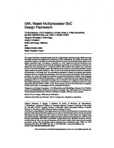
2. How to improve the SoC design flow by UML and SystemC The conventional system level design for SoC currently used at STMicroelectronics is illustrated in Fig. 1.
Fig. 1: Conventional SoC Design Flow The design process starts from the specification of the system requirements – usually written in natural language –; a functional executable model (or algorithmic specification) is modelled from the requirements to capture the system behavior. This is usually done in a software programming language (like C/C++) or by modeling tools such as Simulink [12]. This functional level contains the full model of the system, including hardware and software parts, which are verified together at high level of abstraction checking their conceptual correctness. A fundamental choice – usually dictated by the sense and experience of expert engineers – is the partitioning between hardware and software, that decides the final destination of the various parts of the design. Two separate design flows start for the software and the hardware parts. The software parts are compiled for the target processing elements (see the right side of Fig. 1). In the flow for hardware refinement (see the left side of Fig. 1), instead, there is still a large gap between the specification level and the implementation level. In addition, since the verification of an integrated hardware and software system takes place after both components are completed, errors discovered in the verification phase are often uncorrectable. The hardware part is initially expressed in an hardware description language at RTL; it is then refined to a structural representation using the logic synthesis which produces a netlist which can be mapped on a library of standard cells or hard-macro blocks (blocks for which the layout is already available) for the final implementation. This structural representation is used to produce the final
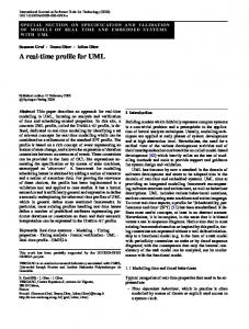
physical layout by the chip floor planning, clock tree synthesis and final automatic placement and routing. Many verification steps are carried out at these design phases: simulation is carried out at functional level to ensure the conceptual correctness of the system; the hardware part is co-simulated at RTL level together with the software parts running on ISSs (Instruction Set Simulators); the correctness of the gate level netlist can be checked with respect to the RTL original representation by formal verification techniques; timing analysis is performed on the gate level netlist to ensure that design time constraints are met; finally, it is verified that the final layout actually corresponds to the gate level netlist. Note that, information about the parasitic capacitances and resistances of the layout is used to back annotate delays; these data are used to perform accurate simulation or timing analysis. We believe that the UML may improve the SoC design flow essentially in tree ways (see Fig. 2): (i) the UML in a platform-independent manner can be adopted at System Functional Executable Model level to describe the specification, like Simulink [12]; (ii) the UML profile for SystemC can be used for the hardware description at the abstraction layers on top of the RTL layer; (iii) UML profiles tailored for programming languages like C/C++, Java, etc. can be used, instead, for the software parts.
Fig. 2: New SoC Design Flow This rising of design abstraction levels that UML allows implies all the advantages of modeling with respect to coding: visualization, reusing, integration, documentation, model analysis and automatic generation of the SystemC code. Moreover, note that, in the new proposed SoC Design Flow, a further validation step, involving both the hardware and the software parts, can be introduced at the transactional level: the software part can be simulated by performing transactions which carry accurate timing information as defined by the hardware architecture model
at transactional level (Transactional Co-simulation in Fig. 2). An open question is whether UML is rich enough to represent hardware adequately. People supporting UML are convinced that the UML with its extension capabilities (called profiles) allows to model any system at any level of details. Indeed, certain diagrams of the new version UML 2.0 [9] are particularly suitable for system level modeling: class diagrams in UML 2.0 allow also to describe class ports that communicate through interfaces; composite structure diagrams show the static system structure (classes with their internal structure including attributes, methods, and relationships with other classes - by means of inheritance, generalisation, and associations -, their ports and interfaces); sequence diagrams could be used to create testbenches; state diagrams model object behavior over several use cases. The approach of defining UML profiles can be repeated for other languages (JHDL [2], SystemVerilog [14], etc.) currently used in the SoC design. The availability of such profiles and the definition of suitable PSM bridges – as conceived by the Model Driven Architecture (MDA) initiative [7] – may allow to move from the description of a system (or just a part of it) in a given language to the description of the same system (or part of it) in another language at the same level of abstraction or lower. In this way, UML enables to establish new development processes, easily adoptable by EDA companies, which allow interchange and reuse of design practices and IP solutions.
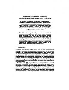
3. A UML 2.0 profile for SystemC A UML profile is a group of extensions - stereotypes, constraints, and tagged values - that add domain-specific information to the UML modeling elements (or a subset of them), possibly altering the notation (by means of icons) and the associated semantics. A UML profile can be intended as a new dialect of the UML for a particular platform or a particular application domain such as banking, telecommunications, aerospace, real time applications, testing, etc. This section introduces a UML profile for the SystemC language based on the UML 2.0 specification [9] and on the SystemC 2.0 specification [16]. A UML profile give a new graphical dimension to SystemC, enforcing the designer to describe systems at “modeling level” rather than designing at a lower level by means of “coding”. The complete UML profile definition for SystemC can be found in [10]; in Fig. 3 we report the most significant stereotypes elements of the proposed profile. The figure is split in two parts: the first part specifies the stereotypes that can be used in various UML structural diagrams (like class diagrams and composite structure diagrams) for representing the structural building blocks of
SystemC; the second part defines stereotypes that can be used in various UML behavioral diagrams (such as UML method state machines) for modeling the functionality expressed by processes and channels in a given SystemC specification.
Fig. 3: UML notation for SystemC concepts In the following subsection, we show how to model a system using our profile.
3.1 A simple communication modeling example Here, the UML 2.0 profile for SystemC is used to model the SystemC specification of a custom FIFO channel taken from [17] and also available in the SystemC 2.0 distribution. A user-defined FIFO channel permits to store characters by means of “blocking” read and write interfaces, such that characters are always reliably delivered. Two processes, the “producer” and the “consumer”, respectively feed and read the FIFO. The producer module writes data through its port into the FIFO by a write_if interface, the consumer module reads data from the FIFO through its port by the read_if interface. These two interfaces are implemented by the FIFO channel. Fig. 4 shows the UML classes of the read_if and write_if interfaces of the given example. According to the UML 2.0 profile for SystemC, interfaces are modelled as classes with the «sc_interface» stereotype. The read interface specifies two public methods: read(char&) to read a character from the FIFO, and num_available() to return the number of characters available for reading in the FIFO channel. The write interface specifies two public
methods: write(char) to write a char into the FIFO, and reset() to set the FIFO to an initial state. The corresponding SystemC code (the header file read_write_if.h) follows. class write_if : virtual public sc_interface { public: virtual void write(char) = 0; virtual void reset() = 0; }; class read_if : virtual public sc_interface { public: virtual void read(char &) = 0; virtual int num_available() = 0; };
void producer::main() { const char *c = "Visit www.systemc.org\n"; out->reset(); while (*c) out->write(*c++); }
According to the UML 2.0 profile for SystemC, the behavior of the main thread process of the producer module may be described by a UML method state machine as shown in Fig. 6. Note that, there is no check that the FIFO channel is not full when the write operation is performed by a process; in that case, the writing thread process is automatically suspended inside the hosting FIFO object (see FIFO channel behavior below).
Fig. 4: read_if and write_if interfaces The producer module (see Fig. 5) is modelled by a class with the stereotype «sc_module» and has a thread process main and a port out requiring the write_if interface. Note that all modules containing thread processes are considered “active”, and are represented by an UML active class, graphically a box with an additional vertical bar on either sides.
Fig. 6: Producer behavior
Fig. 5: Producer module The corresponding SystemC code (the header file producer.h) is reported below. It contains the declaration of the producer class together with the declaration of the thread process. #include "read_write_if.h" class producer: public sc_module { public: sc_port out; void main(); SC_HAS_PROCESS(producer); producer(sc_module_name mn): sc_module(mn) { SC_THREAD(main); } };
Similarly, the consumer module and its reading thread process may be modelled by a class and a state machine. The class representing the hierarchical FIFO channel is reported in Fig. 7. In this example, the FIFO channel provides the actual implementation to the read_if and write_if interfaces. It also contains the data members max, data, num_elements and first, and two events named respectively write_event and read_event declared as private (since they are visible only to the read and write interface methods).
After resetting the FIFO channel, the thread process writes all the characters from a string variable to the out port using the write operation of the write_if interface. The actual implementation of the main thread process (the producer.cpp file) is the following. #include "producer.h"
Fig. 7: FIFO channel
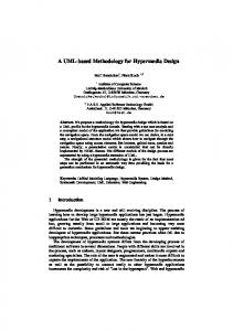
The behavior of the FIFO class providing the actual implementation of the read_if and of the write_if interfaces is modelled by the set of UML method state machines shown in Fig. 8. These state machines are activated by “call events” generated by “call actions” made on ports connected to the FIFO channel. Note that, according to the UML 2.0 profile for SystemC, states with the stereotype «wait» dynamically suspend the calling process until a read_event or write_event (depending on the kind of process) is notified by another process within the scope of the FIFO channel.
wait(write_event); c = data[first]; -- num_elements; first = (first + 1) % max; read_event.notify(); } void fifo::reset() { num_elements = first = 0; } int fifo::num_available() { return num_elements;}
Finally, in order to complete the communication example, a top composite module is defined to contain an instance part of the consumer module, an instance part of the producer module and a FIFO channel part (see Fig. 9 and Fig. 10).
Fig. 9: Top module
Fig. 10: Top composite structure diagram
Fig. 8 FIFO behavior The corresponding SystemC code for the FIFO channel (the fifo.h and fifo.cpp files) is listed below. // file fifo.h #include "read_write_if.h" class fifo : public sc_channel, public write_if, public read_if { public: fifo(sc_module_name mn): sc_channel(mn) { num_elements = first = 0; } void write(char); void read(char&); void reset(); int num_available(); private: enum e { max = 10 }; char data[max]; int num_elements, first; sc_event write_event, read_event; }; // file fifo.cpp #include "fifo.h" void fifo::write(char c) { if(num_elements == max) wait(read_event); data[(first+num_elements)%max] = c; ++ num_elements; write_event.notify(); } void fifo::read(char& c){ if(num_elements == 0)
The composite structure diagram in Fig. 10 shows the internal structure of the top class module as a collaboration structure of interconnected parts and ports. Note that, the dashed notation used for the parts indicates that the top class is responsible for the construction of the inner modules by “dynamic allocation”. The top module is implemented in SystemC as follows (file top.cpp). class top: public sc_module { public: fifo * fifo_inst; //a fifo instance producer * producer_inst; //a producer instance consumer * consumer_inst; //a consumer instance top(sc_module_name mn):sc_module(mn) { fifo_inst = new fifo("Fifo1"); producer_inst= new producer("Producer1"); consumer_inst= new consumer("Consumer1"); producer_inst->out(*fifo_inst); consumer_inst->in(*fifo_inst); } };
4. Related work In cooperation with industrial partners, UML has been deployed in real application scenarios which provided extensive experiences on how to use UML effectively within a system development process. The possibility to use UML 1.x for system design [4,5] started already at Cadence Design Systems in 1999. However, the general opinion was that UML (before version 2.0) was not mature enough as a
system design language, in particular if compared to other emerging system design environments. The work in [6] provides a broad overview of the process and methodology developed and applied internally to the OWL project for OFDM Wireless LAN, for the development of a Wireless LAN chipset based on a modulation technique known as Orthogonal Frequency Division Multiplexing (OFDM). The paper records the experiences of the project team in applying SystemC language as an integral part of the design process for SoC development in conjunction with the UML - using UML stereotypes to represent important structural aspects and SystemC concepts - and the RUP (Rational Unified Process) process to provide visual, structured models and documentation of the architecture design. Considerable synergy was demonstrated between these modeling techniques and the use of SystemC executable models. Fujitsu [18] has developed a new SoC (System-on-aChip) design methodology that employs UML and C/C++/SystemC programming languages. The methodology differs significantly from the conventional System LSI design methodology in two points: (a) the use of the UML to describe the specification; (b) the introduction of UML and C++/SystemC for the phases from the system partition into hardware and software components. All of the above experiences based on the use of C/C++/SystemC languages have in common the use of UML stereotypes for SystemC constructs, but it seems that these are not included in an appropriate and standardized language of something like “UML profile for SystemC”. In this sense, it is appreciable the research work in [3] in attempting to define a truthful UML profile for SystemC; but, as all the above proposals, no code generation capabilities for behavioral information are considered. The use of UML state machines for modules’ behavior description and channels’ protocols specification are underestimate or postponed as future work. Moreover, all of these proposals are based on the old versions of UML (the so called UML 1.x) [8], making difficult and little scalable the structural representation of systems without the architectural constructs offered by the UML in its new version 2.0 [9]. The SysML Partners [13] are customizing UML 2.0 to define a modeling language, Systems Modeling Language (SysML), for systems engineering applications (including the specification, analysis and verification of complex systems with both hardware and software components, personnel, procedures, etc.). Although SysML reuses the second generation of UML, it has to be intended as a general-purpose modeling language – a Platform Independent Modeling (PIM) language, as conceived by the MDA [7] vision –. So it is in agreement with our SystemC UML profile which is a Platform Specific Modeling (PSM) Language. Moreover, since SysML preserves the basic semantics of UML 2.0 diagrams, our SystemC UML profile
can be thought (and effectively made) a customization of SysML rather than UML.
5. Concluding remarks In this paper, we show how UML and UML profiles can be effectively used within a wider scope of application domains such as the SoC design area. UML profiles provide a standardized visual representation easy to learn and supported by a number of tools to design, implementing and document systems. Benefits provided by a standardized UML extension for SystemC may contribute to increase the success of UML and SystemC as IP delivery media.
References [1] P. Alexander, R. Kamath and D. Barton. System Specification in Rosetta. In Proc. of IEEE Engineering of Computer Based Systems Symposium 2000. [2] P. Bellows and B. Hutchings. JHDL – An HDL for Reconfigurable Systems. In Proc. of IEEE Symposium on FPGAs for Custom Computing Machines 1998. [3] F. Bruschi, D. Sciuto. A SystemC based Design Flow starting from UML Model. In Proc. of ESCUG’02.
[4] G. Martin. UML and VCC. Cadence Design Systems, Inc., White Paper, December 1999.
[5] G. Martin, L. Lavagno, J. L. Guerin. Embedded UML: a
merger of real-time UML and co-design. In Proc. of CODES’01. [6] T. Moore, Y. Vanderperren, G. Sonck, P. van Oostende, M. Pauwels, W. Dehaene. A Design Methodology for the Development of a Complex System-On-Chip using UML and Executable System Models. In Proc. of ECSL’02. [7] OMG. The Model Driven Architecture (MDA). http://www.omg.org/mda/. [8] OMG. The Unified Modeling Language, version 1.5. Document formal/01-09-67. [9] OMG, UML 2.0 Superstructure Final Adopted specification. Doc. ptc/03-08-02. http://www.uml.org/. [10] E. Riccobene, P. Scandurra, A. Rosti and S. Bocchio. A UML 2.0 Profile for SystemC. STMicroelectronics Technical Report, 2004. [11] R. Roth and D. Ramanathan. A High-Level Hardware Design Methodology Using C++. In Proc. of the 4th High Level Design Validation and Test Workshop 1999. [12] Simulink. http://www.mathworks.com. [13] SysML Partners web site. http://www.sysml.org/. [14] SystemVerilog. http://www.systemverilog.org. [15] SystemC website: www.systemc.org. [16] SystemC 2.0.1 Language Reference Manual Revision 1.0 Copyright © 2003 Open SystemC Initiative. [17] S. Swan. An Introduction to System Level Modeling in SystemC 2.0. Open SystemC Iniziative (OSCI). White paper, Cadence Design Systems, Inc. May 2001. [18] Q. Zhu, R. Oishi, T. Hasegawa, T. Nakata. System on Chip Validation using UML and CWL. In Proc. of CODES ’04.