286
IEEE ELECTRON DEVICE LETTERS, VOL. 26, NO. 5, MAY 2005
A Nonvolatile Memory Based on Reversible Phase Changes Between fcc and hcp Dong-Ho Ahn, Dae-Hwan Kang, Byung-ki Cheong, Hyuk-Soon Kwon, Min-Ho Kwon, Tae-Yeon Lee, Jeung-hyun Jeong, Taek Sung Lee, In Ho Kim, and Ki-Bum Kim
Abstract—A nonvolatile memory technology utilizing reversible changes between fcc and hcp crystalline phases is proposed. In this new type of phase-change memory, data are stored in different forms of crystalline phases of (Ge1 Sb2 Te4 )0 8 (Sn1 Bi2 Te4 )0 2 chalcogenide alloy. RESET operation produces the less conductive metastable fcc phase via melt-quenching from the more conductive stable hcp phase and SET operation involves a phase change from fcc directly to hcp. Both RESET and SET operations can be completed as fast as 70 ns with large changes in cell resistance. Index Terms—Amorphous semiconductor, chalcogenide, nonvolatile memory, phase transformation, phase-change memory (PCM).
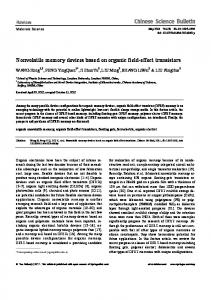
Fig. 1. Schematic diagram and SEM microphotograph of off-set-type memory cell structure.
I. INTRODUCTION
I
N recent years, there has been a renewal of interest in phase-change random access memory (PCRAM) as a promising candidate for next-generation nonvolatile memory device because of many advantages such as nonvolatility, fast operation property, process simplicity, and possibility of multibit operation [1]. So far, almost all phase-change-memory devices have been utilizing reversible structural phase changes between amorphous and crystalline phases of chalcogenide alloys [2]–[5]. Particularly, chalcogenide alloys based on stoichiometric GeSbTe alloys such as Ge Sb Te and Ge Sb Te are most popular due to their remarkable capability of providing fast kinetics of the phase changes. Interestingly, these alloys are known to have electrically distinguishable crystalline phases, namely fcc and hcp phases [6], but little is known about the possibility of constructing a memory device using transitions between these crystalline phases. In this letter, we suggest a new phase-change-memory cell technology utilizing reversible changes between fcc and hcp Sn Bi Te chalcocrystalline phases of Ge Sb Te genide alloy [7].
Manuscript received December 9, 2004; revised February 7, 2005. This work was supported in part by the Korea Ministry of Science and Technology under the National Research Program for 0.1 Terabit Non-volatile Memory Development. The review of this letter was arranged by Editor A. Wang. D.-H. Ahn, H.-S. Kwon, M.-H. Kwon, T.-Y. Lee, and K.-B. Kim are with the School of Materials Science and Engineering, Seoul National University, Seoul 151-742, Korea (e-mail:
[email protected]). D.-H. Kang, B. Cheong, J. Jeong, T. S. Lee, and I. H. Kim are with the Thin Film Materials Research Center, Korea Institute of Science and Technology, Seoul 136-791, Korea. Digital Object Identifier 10.1109/LED.2005.846576
Fig. 2. Dependence of resistivity on annealing temperature. Isothermal annealing was carried out at conventional furnace with argon ambient and resistivity data was obtained from a four-point probe in consideration of film shrink. Insets are TEM images for (a,c) Ge Sb Te and films (a,b) as-deposited sample and (b,d) (Ge Sb Te ) (Sn Bi Te ) (c,d) annealed at 200 C.
II. EXPERIMENTAL Sn Bi Te films were prepared by Thin Ge Sb Te sputter deposition on either glass substrate or SiO-coated TEM grids, followed by isothermal annealing at various temperatures up to 300 C for 15 min in the conventional furnace under an Ar atmosphere. Each film was then characterized in terms of electrical resistivity, crystal structure, and microstructure compared with those of Ge Sb Te alloy. With two kinds of films, we fabricated off-set type phase-change-memory devices having a 100-nm-thick phase-change material and 70-nm contact size. Fig. 1 shows the schematic diagram and scanning electron microscope (SEM) image of devices. Then, the electrical switching characteristics of these devices were characterized by means of transient on-off pulse test and steady-state dc – test.
0741-3106/$20.00 © 2005 IEEE
AHN et al.: NONVOLATILE MEMORY BASED ON REVERSIBLE PHASE CHANGES BETWEEN fcc AND hcp
287
Fig. 3. Transient on/off pulse test results and corresponding steady-state dc I –V characteristics of memory cell with: (a) and (b) Ge Sb Te (c) and (d) (Ge Sb Te ) (Sn Bi Te ) . Insets of (a) and (c) represent the resistance–voltage (R–V ) curves of each phase transition events.
and
III. RESULTS AND DISCUSSION A. Phase-Change Material Properties In Fig. 2, electrical resistivities of the as-deposited and annealed thin films are shown for both Ge Sb Te Sn Bi Te and Ge Sb Te alloys along with structural characteristics at selected temperatures [see the inset transmission microscope (TEM) images from (a) to (d)]. Between the two alloys, differences in electrical resistivities and in structures are most striking in the as-deposited films. In the case of as-deposited Ge Sb Te shown in inset (a), diffraction halos are clearly observed in conjunction with a mostly featureless bright field image due to the prevailing amorphous matrix. In contrast, diffraction ring patterns of inset (b) are due to a defective fcc structure in the case of as-deposited Ge Sb Te Sn Bi Te . As for the films annealed at 200 C, analyses of TEM diffraction patterns led to a single fcc crystalline state for Ge Sb Te film [inset (c)], but a mixed state of fcc and hcp phases for Ge Sb Te Sn Bi Te film [inset (d)]. According to our previous study [7], such an accelerated crystallization in the alloy added with Sn Bi Te is due to the reduced strengths of various interatomic bonds in this alloy. B. Memory Cell Characteristics In order to evaluate the device characteristics of a memory cell with a new phase-change material relative to the one with
Ge Sb Te , a transient pulse test was carried out as shown in Fig. 3. In these measurements, a RESET pulse was fixed at 70 ns and a SET pulse was varied from 1 ms to 70 ns. It is found from Fig. 3(a) that resistance of a memory cell with Ge Sb Te changes from to , by a RESET operation. In Sn Bi Te , the case of a memory cell with Ge Sb Te however, cell resistance does not return to a RESET value from a first SET value but rather drops further to a second SET value, as shown in Fig. 3(c). Also, the cell resistance changes reversibly between the first SET and second SET since then. The resistance Sn Bi Te cell is smaller than that gap of Ge Sb Te of Ge Sb Te . But, it still has one order of magnitude, which is large enough to provide distinguishable binary memory states. Fig. 3(b) and (d) shows the dc – characteristics of a memory cell with each alloy, respectively, in a virgin state and switched states after electrical pulse test. For both alloys, the memory cell in a respective virgin state displays a negative (threshold voltage), resistance behavior with different meaning that initial states are amorphous or amorphous-like (defective). Once switched to a respective first SET state, however, two devices show markedly different characteristics. In the memory Sn Bi Te , – curves of two cell with Ge Sb Te different conducting states are observed and memory switching takes place reversibly between these two crystalline states; the less and the more conductive crystalline states correspond to the first SET and second SET, respectively.
288
IEEE ELECTRON DEVICE LETTERS, VOL. 26, NO. 5, MAY 2005
It should be noticed from inset of Fig. 3(a) and (c) that reSn Bi Te cell took sistance change of the Ge Sb Te place abruptly and rapidly ( 70 ns) at a certain voltage, similarly as in the case of Ge Sb Te cell where switching was accompanied by reversible phase changes between amorphous and crystalline states. In addition, cell resistance values might correspond to the resistivities of two crystalline phases of the Ge Sb Te Sn Bi Te alloy. The details of this mechanism of this unique transition behavior is discussed below. C. Modeling To account for what we observed above, a new model is considered: the phase transformation from fcc to hcp results in resistivity change. In order to check if the new model is applicable, the resistance of memory cell of Ge Sb Te Sn Bi Te should be estimated from the resistivity data shown in Fig. 2. For our device, cell resistance may be expressed as
Fig. 4. Steady-state dc I –V characteristics of memory cell with (Ge Sb Te ) (Sn Bi Te ) which is annealed at 150 C (fcc) and 300 C (hcp). Inset: X-ray diffraction patterns of (Ge Sb Te ) (Sn Bi Te ) film on glass substrate. Annealing conditions of films are (a) 150 C and (b) 300 C for 15 min with argon ambient, and the phases of each film correspond to the fcc and hcp crystalline, respectively.
(1) , Since the metal line and metal contact resistance ( ) are approximately several tens of , cell resistance is primarily determined by phase change material resis. So, simple cell resistance is tance
based alloy materials [6]. Further work is underway for a direct observation of fcc-to-hcp transformation under electrical stress. IV. CONCLUSION
(3) (4) (5)
A new phase-change memory cell using resistance change beSn Bi Te tween two crystalline phases of Ge Sb Te chalcogenide alloy is proposed in this study. As it turned out, the addition of Sn Bi Te into Ge Sb Te not only accelerates the crystallization of Ge Sb Te but also provides a data-storage mechanism distinct from that of a conventional phase-change memory element. In this new phase-change memory device, the high-resistive RESET state due to an amorphous phase is not accessible but data are stored in different forms of crystalline phases. Both RESET and SET operations can be completed as fast as 70 ns with large changes in cell resistance corresponding to the resistivities of two crystalline phases of Ge Sb Te Sn Bi Te .
These calculated values correspond well to the resistivity of , 150 C annealed , and 300 C annealed as-deposited samples, respectively. As shown in the inset of Fig. 4, samples annealed at 150 C and 300 C yield diffraction patterns that can be indexed according to fcc and hcp phases, respectively. Fig. 4 shows the dc – characteristics of the memory cell which is intentionally annealed at 150 C and 300 C. In this annealed memory cell, not only resistance values but also – shapes of high-resistive fcc and low-resistive hcp are coincident with those of the memory cells which were obtained by electrical pulse test. It is considered, therefore, that first SET state is due to fcc structure and second SET state is due to hcp structure. That is, the first SET behavior is related to phase transition from hcp to fcc by way of melt-quenching and second SET behavior is related to one from metastable fcc to stable hcp. It is emphasized that an fcc-to-hcp transition time of 70 ns is far smaller than what is typically required for fcc-to-hcp transformations in GeSbTe-
[1] R. Neale, “Amorphous nonvolatile memory: the past and the future,” Electron. Eng., pp. 67–76, Apr. 2001. [2] S. R. Ovshinsky, “Reversible electrical switching phenomena in disordered structures,” Phys. Rev. Lett., vol. 47, pp. 1450–1453, 1968. [3] K. Nakayama, T. Kitagawa, M. Ohmura, and M. Suzuki, “Nonvolatile memory based on phase transition in chalcogenide thin film,” Jpn. J. Appl. Phys., vol. 32, pp. 564–569, 1993. [4] S. Lai and T. Lowery, “OUM-A 180 nm nonvolatile memory cell element technology for stand-alone and embedded applications,” in IEDM Tech. Dig., 2001, pp. 803–806. [5] Y. N. Hwang, J. S. Hong, S. H. Lee, S. J. Ahn, G. Jeong, G. H. Koh, H. J. Kim, W. C. Jeong, S. Y. Lee, J. H. Park, K. C. Ryoo, H. Horii, Y. H. Ha, J. H. Yi, W. Y. Cho, Y. T. Kim, K. H. Lee, S. H. Joo, S. O. Park, U. I. Chung, H. S. Jeong, and K. Kim, “Phase-change chalcogenide nonvolatile RAM completely based on CMOS technology,” in Symp. VLSI Tech. Syst. Applic., 2003, pp. 29–31. [6] N. Yamada, E. Ohno, K. Nishiuchi, N. Akahira, and M. Takao, J. Appl. Phys., vol. 69, no. 5, pp. 2849–2856, 1991. [7] T.-Y. Lee, K.-B. Kim, B. Cheong, T. Lee, S. J. Park, K. S. Lee, W. M. Kim, and S. G. Kim, “Thin film alloy mixtures for high speed phase change optical storage: A study on (Ge Sb Te ) (Sn Bi Te ) ,” Appl. Phys. Lett., vol. 80, no. 18, pp. 3313–3315, 2002.
(2) where is a resistivity of phase-change material, is is the area of contact the thickness of film (200 nm), and pore region (70 nm 70 nm). From (2), we can calculate the resistivity of phase-change material within the device with Ge Sb Te Sn Bi Te as follows: cm cm cm
REFERENCES