Abstractâ As the large size of test data volume is becoming one of the major problems in testing System-on-a-Chip (SoC), several compression coding schemes ...
7C-4
RunBasedReordering: A Novel Approach for Test Data Compression and Scan Power Hao Fang
Chenguang Tong
Xu Cheng
Micro Processor Research and Development Center of Peking University Beijing, China, 100871 Tel: 086-010-62765828 ext{649,651,801} Fax: 086-010-62756231 e-mail: {fanghao,tongchenguang,chengxu}@mprc.pku.edu.cn
Abstract— As the large size of test data volume is becoming one of the major problems in testing System-on-a-Chip (SoC), several compression coding schemes have been proposed. Extended frequency-directed run-length (EFDR) is one of the best coding compression schemes. In this paper, we present a novel algorithm named RunBasedReordering(RBR), which is based on EFDR codes. Three techniques have been applied to this algorithm: scan chain reordering, scan polarity adjustment and test pattern reordering. The experiment results show that the test data compression ratio is significantly improved and scan power consumption is dramatically reduced. Moreover, our algorithm can be easily integrated into the existing industrial flow with little area penalty.
I. I NTRODUCTION As the feature size decreases, a high degree of functionality is usually integrated into System-on-a-Chip(SoC) in a small silicon area. The complex logic leads to an extraordinarily large size of test data and high scan power consumption, which are the big test challenges. Many coding schemes [1–7, 9–11, 14] have been invented for test data compression. In [7, 10, 11], statistical schemes based on Huffman coding are utilized. However, these methods suffered from high area overhead. On the other hand, runlength methods can make a good trade-off between test data compression ratio and area penalty. Jas and Touba [1] proposed a fix-to-variable coding technique of ”running” 0s sequence. Later, Chandra and Chakrabarty improved this technique using variable-to-variable encoding techniques: Golomb codes [3] and FDR codes [2, 4]. Gonciari et al. [6] proposed an enhanced coding scheme named extended frequency-directed run-length(EFDR). EFDR codes took advantage of both runs of 0’s and runs of 1’s and outperformed the other coding techniques that are based on only runs of 0’s. Recently, Doi et al. [5] tried to adjust scan polarity for better compression result. However, all the above coding schemes assumed that scan chains are fixed, that is, the order of scan cells cannot be changed. Also, to the best knowledge of the authors, there are no algorithms of reordering scan chains for test data compression. In commercial DFT tools, scan chains are usually reordered to save routing resources or avoiding race conditions 1-4244-0630-7/07/$20.00 ©2007 IEEE.
in scan shift mode, not for test data compression. In this paper, we present a novel algorithm named RunBasedReordering(RBR), which is based on EFDR codes. Three techniques have been applied to this algorithm: scan chain reordering, scan polarity adjustment and test pattern reordering. The experiment results show that the test data compression ratio is significantly improved and scan power consumption is dramatically reduced. Moreover, our algorithm can be easily integrated into the existing industrial flow with little area penalty. The paper is organized as follow. Section II describes existing run-length codes and scan chain reordering techniques. Section III presents our algorithm and its refinements for higher compression ratio and lower scan power. Section IV proposes the implementation flow. Section V gives the experimental results. Finally conclusions and future work discussion are given in Section VI. II. BACKGROUNDS A. Run-based codes A run is a sequence of 0s or 1s that can be encoded using two elements: the repeating symbol and the number of times it appears. A run of 0’s is a number of 0s ended with a single 1 while a run of 1’s is a number of 1s ended with a single 0. Almost all of run-length coding schemes [1–4, 7] encode only runs of 0’s. Intuitively, the less the number of runs is, the higher compression ratio will be obtained. EFDR codes encode both runs of 0’s and runs of 1’s to reduce the number of runs. The first two groups of EFDR codewords [6] are shown in TABLE I. A compression example using EFDR codes is given in Fig.1(a) where TD means original test data, TE means compressed test data and |T | means the size of data T. EFDR needs an on-chip decompressor, which loads compressed data from automatic test equipment(ATE) and restores the original test data. The decompressed test data will be dispatched to scan chains. Due to the simplicity of EFDR codes, the area of on-chip decompressor is small. B. Scan chain reordering In mainstream commercial EDA tools such as DFTAdvisor of Mentor Graphics and DFT Compiler of Synopsys, scan
732
7C-4 F1 F2 F 3 F4 F5 F6
TABLE I EFDR CODES Group
Run
Group Tail Code Word Code Word
Length Prefix A1
A2
1
T1 0
0
000
100
2
1
001
101
3
00
01000
11000
4
0
Runs of 0’s Runs of 1’s
01
01001
11001
5
10
10
01010
11010
6
11
01011
11011
1
1
X
1
1
T2 1
0
0
X
0
X
T3 1
X
0
0
0
0
TD0 = 01 111110 00001 00000 TE0 = 000 11010 01001 01010 |TE0 |= 18 (a) EFDR compression result after Xs are filled carefully F1 F4 F 6 F2 F5 F3
chains are connected alphabetically in default mode. As the order of scan chains does not affect chain functions, scan chains reordering techniques have been widely used for various objectives. In most cases, scan chains are reordered after placement. For example, Synopsys DFT Compiler detaches scan chains before placement and then reconnect them during routing, either for reducing wirelength or for preventing race conditions (hold time violations). Moreover, scan chain reordering can be used to reduce scan power [12].
T1 0
0
1
1
1
1
T2 1
1
1
0
0
0
T3 1
0
0
0
0
0
TD1 = 001 1111110 001 00000 TE1 = 001 11011 001 01010 |TE1 |= 16 (b)EFDR Compression result by the algorithm in Fig.2 F1 F¯2 F¯3 F¯4 F¯5 F¯6 T1 0
0
0
0
0
0
T2 1
1
1
1
1
1
T3 1
1
1
1
1
1
TD2 = 0000001 11111111111
III. P ROPOSED RUN BASED R EORDERING A LGORITHM Former work [6] showed that EFDR codes outperformed FDR codes in compression ratio because of the fewer number of runs. Intuitively, the reduction of the number of runs leads: 1) the higher compression ratio of the run-length algorithm and 2) the fewer transitions during scan shift, which indicates lower scan power. This inspired us to further reduce the number of runs. To achieve it, we have designed a new algorithm RunBasedReordering(RBR). RBR includes three techniques: scan chain reordering, scan polarity adjustment and test pattern reordering, which will be described in the following three subsections. A. The basic run-based reordering algorithm Before describing our algorithm, some definitions used in this paper have to be introduced. Scan Frame – A scan frame is a vector of inputs applied to the same scan cells in each test patterns, which contains a number of 0s, 1s, and don’t-cares (Xs). The width of a frame is equal to the number of test patterns. The number of frames is equal to the length of the longest scan chain. An example of test data for a circuit under test (CUT) with 3 test patterns and 6 scan cells is shown in Fig.1(a). In this example there are total of 6 frames, each of which has 3 bits. Incompatible & Compatible – Given two bits i, j ∈ {0, 1, X}, i and j are incompatible if i = 0 and j = 1 or vice versa. All other circumstances are compatible. Distance – The distance between two scan frames is equal to the number of corresponding incompatible bits. This definition is similar to Hamming distance with extention of don’t-care bits. For example, given two frames F1 = (10XX01) and F2 = (001X11), the distance d(F1 , F2 ) is 2 because the first and the fifth corresponding bits in the frames are incompatible.
TE2 = 01011 1110100 |TE2 |= 12 (c)EFDR Compression result by the algorithm in Fig.3 Fig. 1. An example of test data compression
The order of scan frames determines the decompressed test data that will be dispatched to scan chains. No matter how scan frames are reordered, scan chains can be reconstructed to keep consistent with test data. Therefore, we can freely reorder scan frames for better compression ratio. The basic idea of our run-based scan frames reordering algorithm is to minimize the total distance between every two adjacent frames. Since the total distance of frames decreases, the average length of runs increases, which reduces the total number of runs. We represent each scan frame as a vertex in a complete undirected graph G, and the distance between two frames as the weight of an edge. Then our problem goes back to Hamilton problem, which is known as NP-hard and usually solved by various greedy algorithms. The simplest pure greedy algorithm is: choosing as the next frame in a path the one that is closest to the current frame, provided it hasn’t been visited yet. It seems that the Hamilton path of G is the solution to our reordering problem. However, there are two differences between Hamilton path problem and ours. The first one is that the distance of scan frames in our problem may be uncertain while the distance of Hamilton path is certain. Scan frames may contain Xs that have to be eventually filled with care-bits, which leads to distance uncertainty. Considering a single-pattern that has only one test pattern t = (111XXX000) in test data, because every two adjacent frames are compatible, the total distance is zero. In fact, no matter how you fill Xs with 0 and 1, the total
733
7C-4 1 2 3 4 5 6
Assign F1 to the 1st frame; FR ← F1 ; Choose FL that is the closest frame to FR ; Fill Xs in FL , assign FL to the next frame; Compute new FR according to Table II; If any remaining frames, goto 2. Fill-X: fill remaining Xs of the new frames.
U SING FL
TABLE II FR TO COMPUTE THE NEW FR
AND THE OLD
bit of
bit of FL
new FR 0 1 X bit of 0 0 X 0 old
Fig. 2. The Basic Scan Frames Reordering
distance will not be less than 1. This is because the Xs sequence in the middle conceals the incompatibility between the 1 sequence and the 0 sequence. To reveal this incompatibility, we need to fill Xs during reordering operations. The second one is that Hamilton path problem aims at finding the shortest path which visits each vertex exactly once, while our problem aims at finding a frame sequence which can achieve the minimum number of runs. Sometimes the total distance of scan frames is equal to the number of runs. Considering a single-pattern T1 = (00110001), the total distance of T1 is 3 and T1 is divided into 3 runs: 001, 10 and 001. However, in most cases, the total distance is slightly larger than the number of runs. Given another single-pattern T2 = (00010001), the total distance of T2 is 3 but T2 is divided into 2 runs: 0001 and 0001. This is because the single bit of 1 in T2 can occupy the end of runs of 0s, but the two consequent bits of 1 in T1 leads to an additional run of 1s. Due to these differences, we have to extend the pure greedy algorithm in order to get a sequence of scan frames which can achieve the minimum number of runs (shown in Fig.2). Given some scan frames F1 , F2 , . . . , Fn as input, each time we select from the remaining frames as the next frame in the sequence the one that is closest to a reference frame FR . At the beginning, F1 is assigned the first in the frame sequence directly without any reference frame. Then FR is initialized as F1 , according to which we can find the second frame in the sequence. In the subsequent steps, FR is recalculated according to Table II before each frame selection. In the pure greedy algorithm, FR should be equal to the last frame FL in the current sequence, however, in our algorithm, FR is not always set equally to FL . If a bit in FL is X, which may conceal incompatibility, the corresponding bit in FR keeps unchanged. If the corresponding bits in FL and FR are incompatible, the bit in FR is set to X. The reason is that the incompatibility indicates an end of a run, and a new run will be started by the next bit in the test patten. Therefore, we can ignore the distance computed by the ending bit of the former run and the leading bit of the latter one, and set the bit in FR to X. During reordering, if a bit in a frame is X, it is set equally to the corresponding bit in the reference frame, in order to make the run continuous. After reordering, there may still be some X bits in frames, so we need to deal with these bits using operation Fill-X at line 6 in Fig.2. The remaining Xs are filled by the first care-bits that follow them. After scan frames reordering, we use EFDR codes to compress the new test data. Fig.1(b) shows the compression results. Compared with Fig.1(a) without reordering, our algorithm saves two more bits.
1 2 3 4 5 6 7
1 X 1
1
FR X 0 1
1
Assign F1 to the 1st frame, assign FR ← F1 ; Choose FL or F¯L that is the closest frame to FR ; Fill Xs in Fi or F¯L , assign it to the next frame; Flip & record the Fi if needed; Compute new FR according to Table II; If any remaining frames, goto 2. Fill-X: fill remaining Xs of the new frames.
Fig. 3. Scan Frames Reordering with Polarity Adjustment
B. Scan Polarity Adjustment Adjusting scan polarity to improve test data compression is proposed in [5]. Because FDR codes is used to deal with only runs of 0s, the number of 1 will determine the number of runs. The more 0s the test data contain, the more opportunity FDR could have to achieve high compression ratio. In [5], they try to flip the value of scan cells if the number of 1 is more than that of 0, to make 0s in the test data as much as possible. Therefore, the scan polarity adjustment technique is applied to make the test data contain fewer number of 1. As scan polarity adjustment does not require insertion of logic gates on the scan chains, there is no area or delay penalty. In the scan polarity adjustment, we simply change 0 to 1 and 1 to 0 in a frame, while keep X unchanged. This technique can also be adopted into our algorithm to shorten the total distance. Given a set of n frames F1 , F2 , . . . , Fn , after applying scan polarity adjustment to each frame, we get a set of 2n frames F1 , F2 , . . . , Fn , F 1 , F 2 , . . . , F n . When selecting the next frame closest to FR , we must also check the frames after scan polarity adjustment. If an unflipped frame is chosen into the sequence, the corresponding flipped frame will not be considered later, and vice versa. During reordering, we have to record flipping information for chain modification. The refined algorithm is shown in Fig.3. Fig.1(c) shows the results of Fig.1(a) using EFDR codes and the current algorithm. The size of compressed test data is four bits smaller than that of Fig.1(b). Moreover, the algorithm in Fig.3 reduces the number of transitions during scan shifting. C. Test Pattern Reordering Test patterns focused on stuck-at faults can be arranged in any order without losing fault coverage. 1 Traditionally, test pattern reordering [1, 3] is used to minimize the distance between two consecutive patterns in differential coding based
734
1 Test
patterns focused on delay faults can be partly reordered.
7C-4 1 2 3 4 5
Execute the algorithm in Fig.3 without Fill-X; Fill Xs in patterns except boundary Xs; Count 9 types of patterns separately; Fill remaining Xs to balance 01 and 10 patterns; Reorder filled patterns.
F1 F2 F3 F4 F5 F6 F 7 F8 F9 T1 0
0
0
0
0
0
0
0
T2 1
1
0
0
0
0
1
X X
T3 1
1
1
1
1
1
1
1
1
1
T4 0 0 0 0 0 0 1 1 1 (a) Patterns after scan frames reordered Fig. 4. RunBasedReordering F1 F2 F3 F4 F5 F6 F 7 F8 F9
techniques. In our algorithm, we introduce test pattern reordering for gap minimization. If the last bit of a pattern and the first bit of its subsequent pattern are incompatible, there is a gap between them. Such gaps may increase the number of runs. In algorithms shown in Fig.2 and Fig.3, the consecutive Xs at the end of a pattern will be filled with the first care-bit of its next pattern. This can minimize the total number of gaps. When considering the flexibility of test pattern reordering, such filling scheme is no longer optimal. We need a sophistical method that incorporates boundary (leading and ending) Xs filling and test pattern reordering. Since gaps are only related to the boundary bits of patterns, we classify all the test patterns into nine groups: {Gij |i, j ∈ {0, 1, X}}, where i and j present the values of leading bit and the ending bit respectively. |Gij | denotes the number of patterns in Gij . Eventually, Xs in patterns will be filled with carebits and only four groups G00 ,G01 ,G10 and G11 remain. We create a directed graph DG containing two vertexes V0 and V1 . Every eventual test pattern is mapped to a separate directed edge. For example, a pattern in G01 is mapped to an edge from V0 to V1 . There are four types of edges in the DG and the number of every type of edges is equal to the size of corresponding pattern group. Thus, the problem of minimizing the number of gaps is mapped into the problem of adding as few edges as possible to make DG unicursal. This kind of unicursal problem has been solved. The directed graph is unicursal if and only if � � � � (1) �|G01 | − |G10 |� ≤ 1 We apply the pattern reordering technique to the algorithm shown in Fig.3 to form our final algorithm RunBasedReordering(RBR).� The leading and � ending Xs of patterns are filled to minimize �|G01 | − |G10 |� at line 4 in Fig.4. We reorder filled test patterns at line 5 according to the traveling sequence of unicursal problem. Fig.5 demonstrates the effectiveness of RBR. Consider the example in Fig.5(a), which gives the test patterns after scan frames reordered in the algorithm of Fig.3 with 2 ending Xs of the second pattern unfilled. The Fill-X procedure of former algorithms will fill these X according to the leading bit of the third pattern. Fig.5(b) gives the filling result and the compressed data TE1 using EFDR codes. Fig.5(c) adopts our sophistical filling scheme and pattern reordering to get higher compression ratio. Comparing with the two filling schemes, although the Fill-X procedure does not generate a run between the second pattern and the third pattern, there is a gap between the third pattern and the fourth that increase the count of runs. Note that no matter how the patterns in Fig.5(b)� are reordered, � the gap cannot be eliminated as �|G01 | − |G10 |� = 2. Fig.5(c)
T1 0
0
0
0
0
0
0
0
1
T2 1
1
0
0
0
0
1
1
1
T3 1
1
1
1
1
1
1
1
1
T4 0
0
0
0
0
0
1
1
1
TD1 = 000000001 110 0001 111111111110 000001 11 TE1 = 0110001 101 01000 1110110 01010 101 |TE1 |= 30 (b) Patterns filled by the algorithm in Fig.3
F1 F2 F3 F4 F5 F6 F 7 F8 F9 T1 0
0
0
0
0
0
0
T2 1
1
0
0
0
0
1
0
0
T4 0
0
0
0
0
0
1
1
1
T3 1
1
1
1
1
1
1
1
1
0
1
TD2 = 000000001 110 0001 000000001 11111111111 TE2 = 0110001 101 01000 0110001 1110100 |TE2 |= 29 (c) Patterns filled and reordered by RBR Fig. 5. An example of filling Xs
gives better filling scheme and reordered result by RBR that combines filling and reordering and thus get a shorter compressed data and higher compression ratio. The corresponding unicursal directed graph is shown in Fig.6. IV. I MPLEMENTATION F LOW We have modified the existing standard cell flow with our algorithm. Instead of integrating into the executables of industrial tools, we insert it into the current design flow as a separate step that generates scan chains configuration information for reordering. Traditional routing-oriented reordering flow detaches scan chains before placement, and records the information of every scan chain. During routing, the preserved information and scan cells positions are used to optimize and reconnect scan chains, which can save routing resources or avoid race conditions. Our modified flow, shown in Fig.7, is similar to the traditional one. After ATPG tool produces test patterns, we use RunBasedReordering algorithm to get the new configuration of scan frames, which determines the new structure of scan chains. Because commercial tools such as Astro allow to reconnect scan chains by user-defined sequence, this feature can be used to reconstruct scan chains according to the new config-
735
7C-4 ��
�� � ��� ��� � �
���
����
�� ��
�
����
���������
�
����
��
���� ���
�� � � ��
���� ��� ���� ����
���
Fig. 6. Directed Graph of Fig.5(c) dealt by RBR
�
� �����
� ��� �
� �����
� �����
� ������
� �� ��
� ���� �
� �������
� ��
Fig. 8. Comparison between the number of runs
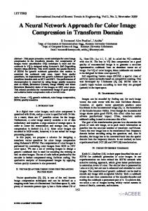
����� � ��� �
power reduction. The comparison of the numbers of runs between EFDR codes and RBR is shown in Fig. 8. RBR reduces the number of runs by 56% on average. The amount of compression obtained is computed as follow:
�������� � �
��� �� � ��
����
� ���� ��� ����� �
CompressionRatio(percent) =
�� $� �� ��� �� � ���� �
���������
��� ����� � � ��� �� � � ����� ��
! ���" ������ ��� �����
��� �����# ������ ��
��! � �
��
� � ���!�
��
� ���
�
Fig. 7. Implementation Flow
uration. As we reorder scan chains for reducing the number of runs without considering the physical locations of scan cells, the reordering of scan chains for minimizing the wire length of scan chains may not be applicable.
Table III presents the experimental results for test cubes TD and compares with the existing coding schemes. Test data size, the number of scan cells(SC) and the number of test patterns(TP) are displayed in the table. We also give the size of compressed bits and the compression ratio(CR) in percent and run time in second of RBR. Except for circuit s9234f, Algorithm 3 outperforms all other coding schemes dramatically. RBR achieves 82.50% compression ratio in average. As the number of runs decreases, the number of transitions during scan shifting is reduced, which lowers scan power. For simplicity, we only consider single scan chain implementation to compute scan power. We use a widely used weighted transitions metric (WTM) introduced in [13] to estimate the power consumption. Suppose test data T = {T1 , T2 , . . . , Tm } have m patterns, and the length of the single scan chain is n. Each test pattern Ti = {ti,1 , ti,2 , . . . , , ti,n }, 1 ≤ i ≤ m contains n bits. ti,j , 1 ≤ i ≤ m, 1 ≤ j ≤ n denotes the j-th bit in the i-th pattern. Weighted transitions metric W T Mj for Tj , the average scan power Pavg and peak scan power Ppeak are estimated as follows: W T Mj =
V. E XPERIMENT R ESULTS We have evaluated RunBasedReordering algorithm with ISCAS-89 benchmarks using C++ language. Only the experiment results of RBR with three scan frames configuration techniques are presented. The experiments are conducted on a workstation with a 2.8GHz Pentium 4 processor and 512 MB of memory. We consider the seven largest full-scan circuits. The test sets TD are obtained from the Mintest ATPG program with dynamic compaction [8]. We use the original test data TD instead of differential coded test data Tdif f to avoid high area overhead. Due to the efficiency in reducing the number of runs, our algorithm outperforms EFDR in compression ratio and scan
(|TD | − |TE |) × 100 (2) |TD |
n−1 �
(n − i) × (tj,i ⊕ tj,i+1 )
(3)
i=1 m �
Pavg = Ppeak
W T Mj
j=1
m = max W T Mj 1≤j≤m
(4) (5)
We computed Pavg and Ppeak of compressed test data dealt by EFDR and our RBR algorithm in table IV. We can see clearly that with the number of runs decrease, RBR algorithm can achieve great power consumption saving. The last column shows the power saving ratios(PSR) between RBR and EFDR computed as: P SR(percent) = (1 −
736
7C-4 TABLE III C OMPARISON OF T EST DATA C OMPRESSION BETWEEN D IFFERENT C ODING S CHEMES
|T D| 23754 39273 165200 76986 28208 164736 199104 -
Circuits s5378f s9234f s13207f s15850f s35932f s38417f s38584f Average
# of SC 214 247 700 611 1763 1664 1464 -
EFDR [6] bits CR(%) 11006 53.67 20162 48.66 28932 82.49 24127 68.66 5415 80.80 62568 62.02 71121 64.28 65.80
# of TP 111 159 236 126 16 99 136 -
EFDR
RBR
Avg
Peak
Avg Peak(%) Avg(%)
s5378f
11522
3525
3661
717
68.23
79.66
s9234f
14103
4022
4717
899
66.55
77.65
s13207f 94886
7892
9379
590
90.12
92.52
s15850f 70894
13659 12092
1839
82.94
86.54
2696
94.70
93.30
s38417f 437935 118077 47399 12292
89.18
89.59
s38584f 481171 86305 115917 18942
75.91
78.05
Average
81.09
85.33
-
-
5780
-
-
RBR CR(%) 68.56 70.14 92.83 85.09 95.57 84.98 80.36 82.50
time(s) 0.03 0.07 0.28 0.16 0.14 0.83 1.14 -
[1] A.Jas and N.A.Touba. Test vector decompression via cyclical scan chains and its application to testing core-based designs. Proc. of International Test. Conference, pages 458–464, Oct 1998.
Power Saving
Peak
s35932f 108957 40214
bits 7469 11727 11847 11477 1250 24746 39099 -
R EFERENCES
TABLE IV C OMPARISON OF P OWER Circuits
SPA [5] bits CR(%) 8502 64.21 10608 72.99 18518 88.79 15900 79.35 13880 50.79 57118 65.33 53774 72.99 70.64
[2] A. Chandra and K. Chakrabarty. Frequency-directed run-length (fdr) codes with application to system-on-a-chip test data compression. Proc. IEEE VLSI Test Symposium, pages 42–47, 2001. [3] A. Chandra and K. Chakrabarty. System-on-a-chip test-data compression and decompression architectures based on golomb codes. IEEE Trans. on Computer-Aided Design of Integrated Circuits and Systems, 20:355–368, March 2001. [4] A. Chandra and K. Chakrabarty. Test data compression and test resource partitioning for system-on-a-chip using frequency-directed runlength (fdr) codes. IEEE Trans. on Computers, 52:1076–1088, Aug 2003. [5] Y. Doi, S. Kajihara, W. Xiaoqing, L. Li, and K. Chakrabarty. Test compression for scan circuits using scan polarity adjustment and pinpoint test relaxation. Proc. of ASP-DAC Asia and South Pacific Design Automation Conference, 1:59–64, Jan 2005. [6] A. El-Maleh and R. Al-Abaji. Extended frequency-directed run-length code with improved application to system-on-a-chip test data compression. Proc. Int. Conf. on Electronics, Circuits and Systems, 2:449–452, Sep 2002.
P owerRBR /P owerEF DR ) ∗ 100%. About 85% average scan power is saved with adopting RBR algorithm.
[7] P. Gonciari, B. Al-Hashimi, and N. Nicolici. Improving compression ratio, area overhead, and test application time for system-on-a-chip test data compression/decompression. Proc. IEEE/ACM Design, Automation and Test in Europe, pages 604–611, March 2002.
VI. C ONCLUSION AND F UTURE W ORK This paper proposed an idea of scan chain reordering for test data compression and presented three novel techniques to configure scan frames based on EFDR codes to minimize the number of runs: scan frames reordering, scan polarity adjustment and test patterns reordering. Our RunBasedReordering can be easily adopted into industrial flow, to get a high test data compression ratio and low scan power with little area penalty. The reordering of scan chains helps obtaining higher compression ratio and lower scan power, however, it sacrifices the possibility of reordering scan chains for minimizing the wire length of scan chains. In the future work, we will consider scan cell physical positions in our RunBasedReordering algorithm, in order to save routing resources and prevent race conditions, while keeping an adequately high test data compression ratio and low scan power. ACKNOWLEDGEMENT We are grateful to Yinhe Han for providing test sets. We also wish to thank Yuanrui Zhang and Kui Wang for their valuable suggestions to improve this work.
[8] I. Hamzaoglu and J. Patel. Test set compaction algorithms for combinational circuits. Proc. Int. Conf. Computer-Aided Design, pages 283–289, Nov 1998. [9] I.Bayraktaroglu and A.Orailoglu. Concurrent application of compaction and compression for test time and data volume reduction in scan designs. IEEE Trans. on Computers, 52(11):1480–1489, Nov 2003. [10] A. Jas, J. Ghosh-Dastidar, and N. Touba. Scan vector compression/decompression using statistical coding. Proc. on VLSI Test Symp., pages 114–120, 1999. [11] A. Jas, J. Ghosh-Dastidar, and N. Touba. An efficient test vector compression scheme using selective huffman coding. IEEE Trans. on ComputerAided Design of Integrated Circuits and Systems, 22:797–806, June 2003. [12] P. Rosinger, P. Gonciari, B. Al-Hashimi, and N. Nicolici. Analysing trade-offs in scan power and test data compression for systems-on-a-chip. IEEE Proc-Comput. Digit Tech., 149:188–196, July 2002. [13] R. Sankaralingam, R. R. Orugani, and N. A. Touba. Static compaction techniques to control scan vector power dissipation. Proc. IEEE VLSI Test Symp., pages 35–40, 2000. [14] M. Tehranipour, M. Nourani, and K. Chakrabarty. Nine-coded compression technique with application to reduced pin-count testing and flexible on-chip decompression. Proc. IEEE/ACM Design, Automation and Test in Europe, Paris, France, 2:1284–1289, Feb 2004.
737