KeywordsâPermanent magnet synchronous motor; Sensorless control; Speed control; Torque control; Field oriented control;. Particle swarm optimization ...
A Novel Sensorless Field Oriented Controller for Permanent Magnet Synchronous Motors Hilmi Aygün, Mustafa Gökdağ, Mustafa Aktaş, Mihai Cernat Electrical-Electronics Engineering Department Karabük University, Karabük, Turkey
Abstract—In this paper, a Particle Swarm Optimization based PI controller (PSO-PI) is used for control the speed and the torque of a Permanent Magnet Synchronous Motor (PMSM) while a Model Reference Adaptive System (MRAS) based on an Artificial Neural Network (ANN) estimation mechanism is applied to estimate sensorless the speed. In order to show the capability of the proposed PSO-PI controller, it is compared with a Fuzzy-Logic PI controller and with a classical PI controller. The simulation results prove the usefulness of the proposed PSO-PI controller.
estimated). The error between the values delivered by the two models is used to estimate the desired variable [29-38]. In every FOC block diagram for PMSM drives, there are three PI controllers. The proportional gain P and the integral time I of these controllers need to be found accurately, since adjusted values of these constants determine better performances of the control [25-27]. In this paper, a PSO-PI controller is used to implement the FOC of the angular speed of a PMSM. In addition, a MRAS based on an ANN is used for the sensorless estimation of the angular speed. For determine the performance of the proposed PSO-PI controller, the results are compared with those of a FuzzyLogic PI controller and of a classical PI controller. Additionally, the performances of the MRAS-ANN estimator are compared with those of two different estimators: an PI speed estimator, and an PSO-PI speed estimator.
Keywords—Permanent magnet synchronous motor; Sensorless control; Speed control; Torque control; Field oriented control; Particle swarm optimization; Artificial neural network, Model reference adaptive system;
I.
INTRODUCTION
In last years, there were important developments in power electronics devices and digital signal processors that allowed replacing induction motors by permanent magnet synchronous motors (PMSM), in drives of a large domain of powers. In comparison with the induction motors, PMSMs present important advantages such as compact structure, high air-gap flux density, high power density, high torque capability, and decreased rotor losses [1]. The Field Oriented Control (FOC) method is a vector control method that presents the advantages of providing smooth starting and acceleration, and of obtaining an effective dynamic response with reduced torque ripples. Hence FOC is applied frequently in PMSM drives, too. [2]. FOC can be implemented with or without shaft sensors. Shaft sensors such as optical encoders or resolvers are generally used in AC drives to identify the rotor position and the speed. However, systems using shaft sensors have increased complexity, volume and cost. The control without sensors is more reliable and may show better dynamic performances. Several techniques for sensorless operation have been developed [3, 4]. One of these techniques is the Model Reference Adaptive System (MRAS) that models the drive by choosing a state variable from the motor’s variables (such as power or current). This state variable is obtained in two different ways: by calculus, using a reference model (which does not include the variable to be estimated) and directly from an adjustable model (which includes the variable to be
978-1-4799-2399-1/14/$31.00 ©2014 IEEE
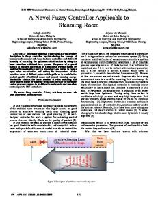
II. THE FIELD ORIENTED CONTROL OF PMSM The FOC method, with its flux/torque decoupling feature, seems to be actually the best alternative in PMSM drives. The goals of FOC are to control the torque variations, the mechanical speed and also to regulate the stator phase currents in order to prevent current spikes during transient phases [6]. The PMSM control strategy using FOC, provides that the current of the stator, expressed in a synchronous rotating d-q frame [5], is controlled as shown in Fig. 1. The equations of the PMSM in the d-q rotor reference frame are:
L d isd R V = − s isd + ω r q isq + sd dt Ld Ld Ld
d isq dt
=−
Ψ f Vsq Rs L isq − ω r d isd − ω r + Lq Lq Ld Lq
(1)
(2)
Ψsd = Ld isd + Ψ f
(3)
Ψsq = Lq isq
(4)
where Rs is the resistance of the stator coil, id and iq are the d-q axis currents, vd and vq are the d-q axis voltages, Ld and Lq are the d-q axis inductances, wr is the angular velocity, Ψsd and Ψsq are the the d-q axis fluxes, Ψf is the flux of the permanent
715
magnet. The electromagnetic torque Te and the position of the rotor ϑr are expressed by: Te =
3 p Ld − Lq isd isq + isq Ψ f 2
[(
p ϑr = 2J
)
]
2 Te − β f ωr − TL p
particles in the problem space, similar to a swarm of mosquitoes [14]. The expressions of the speed and of the position xi of the ith particle of the swarm at the (t+1)th iteration) are [10, 11] :
(5)
[
(
(6)
)]
(8) (9)
where D is the dimension of the hyperspace; r1 and r2 are random parameters valuated between 0 and 1; c1 and c2 are positive constants that pull the particle to local and global best positions; pi is the local best position of ith particle; g is the global best position of the particle in the swarm; K is a factor improving the convergence of optimization, expressed as [12]:
K=
2 2 − ϕ − ϕ 2 − 4ϕ
ϕ = c1 + c2 > 4
(10)
The position and the speed of the particles must be limited for preventing that the particles leave the swarm. These limits are [13]:
vmax = k xmax = −vmin vmin = − vmax
0 .1 ≤ k ≤ 0 .5
(11) (12)
If vk+1 is bigger than vmax then vk+1 is equalized to vmax and if vk+1 is smaller than vmin then vk+1 is equalized to vmin. If xk+1 is bigger than xmax then xk+1 is equalized to xmax and if xk+1 is smaller than xmin then xk+1 is equalized to xmin. Here k is the iteration number. Six steps, as described below are performed to find the optimized parameters [14]. Step 1: The limits for each particle and the values of the parameters used in the Eqs. (8) and (9) are determined. Step 2: The initial speed and position values are appointed with the random numbers in predetermined ranges. Step 3: For every particle, the fitness value is calculated according to the selected fitness function and compared with the fitness value of the local best position. If the current fitness value of the particle is bigger than the fitness value of its local best position, the position and the fitness values of current particle are appointed as new local best values. Step 4: The matrix of the local best position is compared with the matrix containing fitness values of the global best position. If the best fitness value of the local best position matrix is bigger than the fitness value of the global best position, the position and fitness value of that particle are appointed as the new global best values. Step 5: The speeds and positions of particles are updated according to the Eqs. (8) and (9). Step 6: The evolutionary process is repeated from step 3 to step 5 until the iterations are finished. At the end of the iterations, the obtained global best position is assumed as the solution of the problem.
Figure 1. Field oriented control block diagram for a PMSM.
Hence, the electromagnetic torque is linearly related to the isq component of the current [8]:
3 p Ψ f isq = k t isq 2
(
x ti D+1 = xti D + vti D ∆t
where p is the number of the poles pairs, J is the inertia moment, TL is the load moment and βf is the friction coefficient. As it can be seen in Fig. 1, in FOC, the Clarke transformation (a-b-c to α-β) and the Park transformation (α-β to d-q) are used to simplify the equation system. Then the flux-linkage is controlled using the d-axis stator current while the torque is controlled using the q-axis stator current [7]. Since the position of the d axis component of the magnetic flux phasor in a synchronous machine coincide with the rotor shaft position, the position of the magnetic flux phasor can be found by speed estimation. According to Eq. (3), if id = 0 (it is strived to fix as zero in a closed loop control), the d-axis flux linkage Ψd will equal the Ψf which is constant.
Te =
)
vti D+1 = K vti D + c1 r1 p ti D − xti D + c2 r2 g ti D − xti D
(7)
III. PROPOSED CONTROL AND ESTIMATION METHODS A. The Particle Swarm Optimization Controller PSO is an computation technique developed by Eberhart and Kennedy in 1995, who were inspired by the social behavior of bird flocking and fish schooling. PSO utilizes a “population” of particles that fly through the problem hyperspace with given velocities. At each iteration, the velocities of the individual particles are stochastically adjusted according to the historical best position for the particle itself and the neighborhood best position. Both the particle best and the neighborhood best positions are derived according to a fitness function, defined by the user. The movement of each particle naturally evolves to an optimal or near-optimal solution. The word “swarm” comes from the irregular movements of the
716
Fig. 2 shows the block diagram of the proposed PSO-PI controller.
The output variables are the P and I parameters for all controllers. The block diagram of the Fuzzy Logic PI Controller is shown in Figure 3.
Figure 2. Block diagram of the proposed PSO-PI controller.
B. The Fuzzy Logic Controller The Fuzzy Logic, is widely used in machine control. It was advanced by Lotfi A. Zadehy in the 1960s and is based on the concept of "linguistic variables". The term "fuzzy" refers to the fact that the logic involved can deal with concepts that cannot be expressed as "true" or "false" but rather as "partially true". Fuzzy Logic determines the controller’s parameters based on the error and the error change of the controlled quantity, in order to overcome the uncertainties [15]. A Fuzzy Logic system consists of three steps: fuzzification, fuzzy inference and defuzzification. In the fuzzification step, the input and the output variables are translated into linguistic variables by using membership functions. In our fuzzy system, both input and output variables have 5 fuzzy membership functions. These membership functions are Negative Big (NB), Negative Small (NS), Zero (Z), Positive Small (PS) and Positive Big (PB). In the fuzzy inference step, the rule table which defines the behavior of system is determined. In Table 1, the rule base of the Fuzzy Logic based PI controller is shown for both P and I parameters. The first line shows the membership functions of error and the first column shows the membership functions of error change. The defuzzification step translates linguistic result into a real value by using the provided rule table.
Figure 3. Block diagram of fuzzy logic based PI controller.
C. The Artificial Neural Network Artificial neural networks are computational models inspired by animals' central nervous systems (in particular the brain) that are capable of machine learning and pattern recognition, after a training process. They are usually presented as systems of interconnected "neurons" that can compute values from inputs by feeding information through the network [28]. Artificial Neural Networks (ANN) has important advantages such as good adaptation, fast data processing and high computation rate [16]. In this study, for the ANN training was used the back propagation algorithm. Firstly the output of the ANN is calculated by randomly initialized weights of the ANN. Then, the error of the output is calculated and compared with the desired value. Lastly, the previous weights of the layers are updated by back propagation. The relations among the input, the activity level of neurons, and the output of the system are expressed by [16]:
Table 1: The rule base of the Fuzzy Logic based PI controller with 25 rules
a = w0 + w1i1 + w2 i2 + L + wn in
(13)
o = f (a )
(14)
where w and i are the weights of the layers and inputs of the networks, respectively, wo is the bias value, a is the activity level of the neuron, o is the output of the neuron. The error gradient vector ∇e and the weight increment ∆w are calculated as follows:
NB
NS
Z
PS
PB
NB
PB
PB
PS
PS
Z
NS
PB
PS
PS
Z
NS
∇e = −(d − o ) f ' w0 + wT I I
(15)
Z
PS
PS
Z
NS
NS
∆w = −η (d − o ) f ' (a ) I
(16)
PS
PS
Z
NS
NS
NB
PB
Z
NS
NS
NB
NB
(
)
where d is the desired value of the output and η is the learning factor. For n neurons we will have:
∆w j = −η ( d − o ) f' ( a ) I j The Fuzzy Logic PI Controller, which is used to compare the results with those of the proposed PSO-PI controller, has a pair of input variables (the error and the error change) for each control variable (the iq current, the iq current and the speed).
j = 0, 1, 2, L , n
(17)
The updated weights are calculated as follows:
w j new = w j old + ∆w j
717
j = 0, 1, 2, L , n
(18)
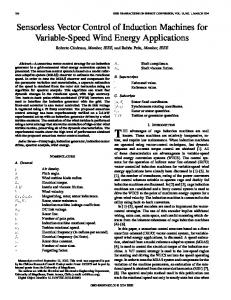
simulations. A series of tests are applied to check the performance of the system. Firstly, the influence of change in the load torque on the drive performance was investigated. Fig. 5 shows the speed response of PI, Fuzzy-PI and PSO-PI controllers, respectively, when the reference speed is 300 rad/s and the load torque, 2 Nm is applied at t = 1 s. Fig. 5 shows also the error between the reference speed and the actual speed under load torque variation. The simulation results demonstrate that the proposed PSO-PI controller reduces very much the ripple and the settling time at the moment of load torque variation, in comparison with the other used controllers: PI and Fuzzy-Logic PI. In Fig. 5, it can be seen also that the Fuzzy-Logic PI controller has better performances than the classical PI controller. Secondly, the influence of change in the reference speed on the drive performance was investigated. Also Fig. 6 shows the drive performance based on PI, Fuzzy-Logic PI and PSO-PI controllers, when at t = 1 the reference speed is decreased without load torque variation, from 300 rad/s to 275 rad/s. Also Fig. 6 shows the error between the reference speed and the actual speed by variation of the reference speed. The simulation results indicate that the proposed PSO-PI has the best performance as compared to all other controllers. The overshoot for PSO-PI is almost the same with the Fuzzy-Logic PI but the settling time for PSO-PI is substantially less than those of the Fuzzy-Logic PI. It can be also seen that the classical PI controller has the worst performance. Lastly, the influence of the estimation methods was investigated for the sensorless FOC of PMSM. Fig. 7 shows the capability of the PI estimator, the PSO-PI estimator and the MRAS-ANN estimator, under no load torque variation. Fig. 7 shows also the error between the actual speed and the estimated speed. The simulation results demonstrate that MRAS based on ANN estimation method has an effective estimation capability and it has better performance than PI and PSO-PI estimation methods.
D. The Proposed Speed Control and Estimation Technique A sensorless FOC method using a PSO-PI controller was applied for control the speed and the torque of a PMSM. A Model Reference Adaptive System (MRAS) based on an ANN, is proposed to estimate sensorless the speed. Using this method, the input values of the ANN were the previous value of rotor speed and the components of the stator current and voltage. The proposed speed estimation method updates the weights of the ANN according to the error of the active power [18, 19]. The actual active power and the estimated active power can be written as follows:
Pa = Vsd isd + Vsq isq
(19)
disq disd ˆrLq isq isd +Ri ˆrLd isd +ω ˆrΨf isq (20) Pˆa =Ri −ω +ω s sd +Ld s sq +Lq dt dt where
wˆ r is the estimated speed and Φf is the flux of the
permanent magnet. The block diagram of the proposed MRAS rotor speed estimator with ANN is shown in Fig. 4.
Figure 4. Proposed MRAS based rotor speed estimator with ANN.
V.
The weights related to the ANN estimation algorithm of the rotor speed, based on MRAS, are determined as follows [18]: 1. The weights are chosen randomly between -1 and +1. 2. Tangent sigmoid activation function is selected in the first layer and Purelin activation function is selected in the last layer. 3. After the input values are applied to the network, the rotor speed value is calculated. 4. The network error is calculated by using the actual and the estimated active powers. 5. The back propagation algorithm is applied to update the weights. 6. At the end of the network training, the rotor speed value is delivered.
CONCLUSIONS
In this paper a comparative study to achieve the sensorless speed control of PMSM using classical PI controller, Fuzzy-PI controller and PSO-PI controller was presented. A Model Reference Adaptive System (MRAS) based on an ANN estimation mechanism was used to estimate the speed. The speed estimation was also supported by a PSO tuned PI controller. Simulation results proved that the proposed control system with speed estimation has better results in terms of settling time and overshoot than that of the classical PI and Fuzzy-PI. The simulation results suggest that the proposed PSO-PI controller with MRAS based on ANN estimation method has considerably better performances than the other methods. The proposed control method achieves fast response to load torque and speed variations, and significantly reduces settling time and overshoot. Furthermore the algorithm of PSO is simple and more effective.
IV. SIMULATION RESULTS In this section, the effectiveness of the proposed method for the sensorless FOC of PMSM is verified by computer
718
speed(rad/s)
350
300
300
250
250
200
200
150
150
100
100
50 classical PI controller PSO-PI controller FUZZY-PI controller
50
0
0
0.2
0.4
0.6
0.8
1 t(s)
1.2
1.4
1.6
1.8
error of classical PI controller error of PSO-PI controller error of FUZZY-PI controller
0
-50
2
0
0.2
0.4
0.6
0.8
1
1.2
1.4
1.6
1.8
2
Figure 5. The speed and the error versus time under load torque variation (from 0 to 2 Nm) on three control methods 300
350
300
200 speed(rad/s)
speed(rad/s)
250
200
150
100
150
100
50 classical PI controller PSO-PI controller FUZZY-PI controller
50
0
error of classical PI controller error of PSO-PI controller error of FUZZY-PI controller
250
0
0.2
0.4
0.6
0.8
1 t(s)
1.2
1.4
1.6
1.8
0
-50
2
0
0.2
0.4
0.6
0.8
1 t(s)
1.2
1.4
1.6
1.8
2
Figure 6. The speed and the error versus time at no load condition on three control methods
350
250
300
200
250
150 100
150
speed(rad/s)
speed(rad/s)
200
100 50
50 0 -50
0 actual wr In PSO-PI controller based on PI speed estimator In PSO-PI controller based on PSO-PI speed estimator In PSO-PI controller based on ANN speed estimator
-50 -100 -150
speed estimation error of PI estimator speed estimation error of PSO-PI estimator speed estimation error of ANN estimator
0
0.2
0.4
0.6
0.8
1 t(s)
1.2
1.4
1.6
1.8
-100 -150 -200
2
0
0.2
0.4
0.6
0.8
1 t(s)
Figure 7. The estimation capability of three speed estimators (speed and error versus time)
719
1.2
1.4
1.6
1.8
2
[20] E. Çam, “Application of fuzzy logic for load frequency control of hydroelectrical power plants”, Energy Conversion and Management, Vol. 48, pp. 1281-1288, 2007. [21] A. Zilouchian, M. Jamshidi, “Intelligent Control Systems Using Soft Computing Methodologies“, Boca Raton, FL, 2001. [22] W. Yan, H. Lin, H. Li, H. Li, J. Lu, “A MRAS based speed identification scheme for a PM synchronous motor drive using the sliding mode technique”, International Conference on Mechatronics and Automation, pp. 3656-3661, 2009. [23] M. Aktaş, H.I. Okumuş, “Stator resistance estimation using ANN in DTC IM drives”, Turkish Journal of Electrical Engineering and Computer Sciences, Vol. 18, pp. 197-210, 2010. [24] S. Maiti, C. Chakraborty, “An adaptive stator resistance estimation technique for sensorless permanent magnet synchronous motor drive”, International Journal of Automation and Control, Vol. 3, pp. 189-201, 2009. [25] P. Brandstetter, T. Krecek, “Speed and Current Control of Permanent Magnet Synchronous Motor Drive Using IMC Controllers“, Advances in Electrical and Computer Engineering, Vol. 12, issue 4, pp.310, 2012. [26] N. Bekiroglu, S. Ozcira, “Observerless Scheme for Sensorless Speed Control of PMSM Using Direct Torque Control Method with LP Filter“, Advances in Electrical and Computer Engineering, Vol. 10, issue 3, pp. 78 – 83, 2010. [27] T, Tudorache, I. Trifu, C. Ghita, V. Bostan, “Improved Mathematical Model of PMSM Taking into Account Cogging Torque Oscillations“, Advances in Electrical and Computer Engineering, Vol. 12, issue 3, pp. 59–64, 2012. [28] C. Cernazanu, “Training neural networks using input data characteristics“, Advances in Electrical and Computer Engineering, Vol. 8, issue 2, pp 65 – 70, 2008. [29] M. Jain, M. Singh, A. Chandra, S.S. Williamson, “Sensorless control of permanent magnet synchronous motor using ANFIS based MRAS“, 2011 IEEE International Electric Machines & Drives Conference (IEMDC), pp. 599 – 606, 2011. [30] Shicai Fan, Wuqiao Luo, Jianxiao Zou, Gang Zheng, “A Hybrid Speed Sensorless Control Strategy for PMSM Based on MRAS and Fuzzy Control“, 7th International Power Electronics and Motion Control Conference (IPEMC),Vol. 4, pp. 2976 – 2980, 2012. [31] P. Kumar, N. Kaushik, S. Dahiya, “Simulation of Sensorless Speed Control of PMSM Based on FOC Method with MRAS Adaptive Speed Estimator“, 2013 Annual IEEE India Conference (INDICON), pp. 1–5, 2013. [32] G. Shahgholian, M.H.Rezaei, A. Etesami, M.R. Yousefi, Simulation of Speed Sensorless Control of PMSM based on DTC method with MRAS, 2010 IPEC Conference Proceedings, pp. 40-45, 2010. [33] A. Mishra, V. Mahajan, P. Agarwal, S.P. Srivastava, “MRAS Based Estimation of Speed in Sensorless PMSM Drive“, 2012 IEEE Fifth Power India Conference,pp. 1 – 5, 2012. [34] Zhang Bingyi, Chen Xiangjun, Sun Guanggui ;Feng Guihong, “A Position Sensorless Vector-control System Based on MRAS for Low Speed and High Torque PMSM Drive“, Proceedings of the Eighth International Conference on Electrical Machines and Systems, ICEMS 2005, Vol. 2, pp, 1682 – 1686, 2005. [35] Yingpei Liu, Janru Wan, Guangye Li, Chenhu Yuan, Hong Shen, “MRAS Speed Identification for PMSM Based on Fuzzy PI Control“, 4th IEEE Conference on Industrial Electronics and Applications, 2009. ICIEA 2009, pp. 1995–1998, 2009. [36] Hui-ying Dong, Wen-guang Li, Yu Zhao, Kai Lin, “Design and Simulation a Fuzzy-adaptive PI Controller Based on MRAS“, 2010 Sixth International Conference on Natural Computation (ICNC), Vol. 5, pp. 2321–2324, 2010. [37] Ruzhong Yan, Beizhi Li, Fu Zhou, “Sensorless control of PMSMs based on parameter-optimized MRAS speed observer“, IEEE International Conference on Automation and Logistics, ICAL 2008, pp. 1573 – 1578, 2008. [38] Fu Zhou, Jianguo Yang, Beizhi Li, “A Novel Speed Observer Based on Parameter-optimized MRAS for PMSMs“, IEEE International Conference on Networking, Sensing and Control, ICNSC 2008, pp, 1708 – 171, 2008.
REFERENCES [1]
[2]
[3]
[4]
[5]
[6]
[7]
[8]
[9]
[10]
[11]
[12]
[13]
[14]
[15]
[16]
[17]
[18]
[19]
K-K. Shyu, C-K. Lai, Y-W. Tsai, D-I. Yang, “A newly robust controller design for the position control of permanent-magnet synchronous motor”, IEEE Transactions on Industrial Electronics, Vol. 49, pp. 558-565, 2002. B. Adhavan, A. Kuppuswamy, G. Jayabaskaran, V. Jagannathan, “Field oriented control of permanent magnet synchronous motor (PMSM) using fuzzy logic controller”, Recent Advances in Intelligent Computational Systems, pp. 587-592, 2011. L. Praly, A. Astolfi, J. Lee, K. Nam, “Estimation of rotor position and speed of permanent magnet synchronous motors with guaranteed stability”, IEEE Transactions on Control Systems Technology, Vol. 19, pp. 601-614, 2011. H.M. Kojabadi, M. Ghribi, “MRAS-based adaptive speed estimator in PMSM drives”, 9th IEEE International Workshop on Advanced Motion Control, pp. 569-572, 2006. Y-S. Kung, M-S. Wang, C-C. Huang, “DSP-based Adaptive Fuzzy Control for a Sensorless PMSM Drive”, Control and Decision Conference, pp. 2379-2384, 2009. Y. Gu, Y. Shı, J. Wang, “Sensorless vector control of AC servo system with artificial neural network observer and fuzzy speed controller”, Przeglad Electrotechniczny, pp. 150-153, 2012. Y-S. Kung, N.V. Quynh, C-C. Huang, “Design and simulation of adaptive speed control for SMO-based sensorless PMSM drive”, International Conference on Intelligent and Advanced Systems, Vol. 1, pp. 439-44, 2012. T. Ming, G. Lin, L. Deliang, “Sensorless permanent magnet synchronous motor drive using an optimized and normalized extended Kalman filter”, International Conference on Electric Machines and Systems, pp. 1-4, 2011. H. Mahmoudi, A. Essalmi, “Neuro-Genetic sensorless sliding mode control of a permanent magnet synchronous motor using Luenberger observer”, Journal of Theoretical and Applied Information Technology, Vol. 53, pp. 236-246, 2013. H. Lesani, A. Darabi, Z. Nasiri Gheidari, F. Tootoonchian, “Very fast field oriented control for permanent magnet-hysteresis synchronous motor”, Iranian Journal of Electrical & Electronic Engineering, Vol. 2, pp. 34-40, 2006. M.B.B. Sharifian, T. Herizchi, K.G. Firouzjah, “Field oriented control of permanent magnet synchronous motor using predictive space vector modulation”, IEEE Symposium on Industrial Electronics and Applications, Vol. 2, pp. 574-579, 2009. S. Jiang, J. Liang, Y. Liu, K. Yamazaki, M. Fujishima, “Modeling and co-simulation of FPGA-based SVPWM control for PMSM”, Industrial Electronics Society, 31st Annual Conference of IEEE, pp. 610, 2005. M.S. Merzoug, F. Naceri, “Comparison of field-oriented control and direct torque control for permanent magnet synchronous motor (PMSM)”, World Academy of Science, Engineering and Technology, pp. 299-304, 2008. J. Kennedy, R. Eberhart, “Particle swarm optimization”, Proceedings of the IEEE International Conference on Neural Networks, Vol.4, pp. 1942-1948, 1995. H. Gözde, M.C. Taplamacioğlu, I. Kocaarslan, E. Cam, “Particle swarm optimization based load frequency control in a single area power system”, Scientific Bulletin of Electronics and Computers Science, Vol. 2, pp. 106-110, 2008. F. Kulic, D. Matic, B. Dumnic, V. Vasic, “Optimal fuzzy controller tuned by TV-PSO for induction motor speed control”, Advances in Electrical and Computer Engineering, Vol. 11, pp. 49-54, 2011. Z-L. Gaing, “A particle swarm optimization approach for optimum design of PID controller in AVR system”, IEEE Transactions on Energy Conversion, Vol. 19, pp. 384-391, 2004. J. Chen, Z. Ren, X. Fan, “Particle swarm optimization with adaptive mutation and its application research in tuning of PID parameters”, Proceedings of the 1st International Symposium on Systems and Control in Aerospace and Astronautics, pp. 19-21, 2006. H. Aygun, H. Demirel, M. Cernat, “Control of the bed temperature of a circulating fluidized bed boiler by using particle swarm optimization”, Advances in Electrical and Computer Engineering, Vol. 12, pp. 27-32, 2012.
720
Powered by TCPDF (www.tcpdf.org)