IEEE TRANSACTIONS ON INDUSTRY APPLICATIONS, VOL. 37, NO. 6, NOVEMBER/DECEMBER 2001
1777
Field-Oriented Control of an Induction Motor Using Random Pulsewidth Modulation Michael M. Bech, Member, IEEE, John K. Pedersen, Senior Member, IEEE, and Frede Blaabjerg, Senior Member, IEEE
Abstract—The principle of field-oriented control (FOC) is a well-established means to obtain a high-performance drive, but the de facto standard FOC does not solve an important secondary problem for inverter-fed motors: the acoustic noise emitted from the motor is tonal due to the constant switching frequency operation. This may be very annoying, even if the exposure time is short. On this background, this paper proposes a classic FOC synchronized to a current-controlled pulsewidth modulation inverter operating with a random switching frequency. This implies that the sampling frequency of both the current controller and the flux estimator is nonuniform, but nevertheless, it is shown that the good dynamic response inherited from the FOC can be maintained while lowering the subjective acoustic annoyance to a great extent due to the random switching frequency operation. Besides laboratory test results documenting the dynamic and steady-state characteristics of the proposed system, design considerations are presented. Index Terms—Acoustic noise, current control, nonuniform sampling, field orientation, random modulation.
I. INTRODUCTION
C
OMMERCIAL drives based on vector-control techniques are readily available, but, nevertheless, the area is still subjected to intensive research aiming at enhancing the performance. Literally, hundreds of new publications on vector control appear each year trying to improve parts of the schemes by, e.g., autocommissioning and online adaptation of parameters. Also, the difficult task of having fast and accurate torque and speed control almost down to zero speed without any mechanical feedback has been solved by real-time evaluation of sophisticated algorithms implemented in digital signal processors (DSPs) [1]. Based on these observations, it may seem difficult to make new contributions in the field of vector-controlled drives. However, apart from drives incorporating freerunning hysteresis current controllers and methods based on the direct torque control (DTC) principle, the steady-state operation due to vector control results in essentially periodic switching patterns as do volts per hertz schemes. This deterministic operation causes harmonic components in the voltage and the current fed to the motor,
i.e., the risk of severe acoustic noise problems is not overruled by using vector control schemes. The problem may be abated during low-load operation by field weakening, which, however, may jeopardize the stability of the drive. On this background, the motivation for this paper is to show that it is possible to use FOC and simultaneously relieve the acoustic noise without necessarily escaping to the method of reducing the magnetizing flux below its rated value. This goal has been achieved by embedding a random pulsewidth modulation (RPWM) into the FOC, because RPWM has been shown by numerous independent sources including [2]–[5] to give less acoustic annoyance than regular-sampled modulators, like space-vector modulation. Although prototypes of vector-controlled induction machines using some kind of RPWM to generate the switching patterns have been reported recently by [6], [7], and also partly in [8], it is the opinion of the authors that several important details have not yet been investigated. For example, fixed-frequency RPWM schemes are used in both publications, but as pointed out in, e.g., [4] and [9], the reduction of the acoustic annoyance is much better for random switching frequency PWM (RSF-PWM) than for the random lead–lag (RLL) type of modulation used in [7]; see Section III for further comments on the work of [6]–[8]. This paper focuses on the RSF-PWM and it is shown how this scheme may be incorporated into a standard vector controller despite the fact that the sampling frequency of the innermost control loop is synchronized to the randomly varying switching frequency of the inverter. The organization of this paper is as follows. First, the proposed system is presented and, next, a discussion of related work dealing with RPWM in closed-loop applications is provided. Then, a few RPWM techniques suitable for three-phase applications are discussed and the difficulties pertinent to using RPWM in high-performance feedback systems are outlined. Next, it is shown how a field-oriented controller operating at a nonuniform sampling rate may be designed and implemented in a sampled system. Finally, experimental results are presented. II. OVERALL SYSTEM PRESENTATION
Paper IPCSD 01–060, presented at the 2000 IEEE Applied Power Electronics Conference and Exposition, New Orleans, LA, February 6–10, and approved for publication in the IEEE TRANSACTIONS ON INDUSTRY APPLICATIONS by the Industrial Drives Committee of the IEEE Industry Applications Society. Manuscript submitted for review February 10, 2000 and released for publication September 5, 2001. The authors with the Institute of Energy Technology, Aalborg University, DK-9220 Aalborg East, Denmark (e-mail:
[email protected];
[email protected];
[email protected]). Publisher Item Identifier S 0093-9994(01)10075-7.
A system block diagram is shown in Fig. 1. The control system is a simple direct rotor-field-oriented controller using cascaded feedback loops: A fast stator current controller and an outer speed control loop. Since the control is implemented in rotor-field coordinates, transformations are included to convert and the synchronous space vectors between the stationary reference frames.
0093–9994/01$10.00 © 2001 IEEE
1778
IEEE TRANSACTIONS ON INDUSTRY APPLICATIONS, VOL. 37, NO. 6, NOVEMBER/DECEMBER 2001
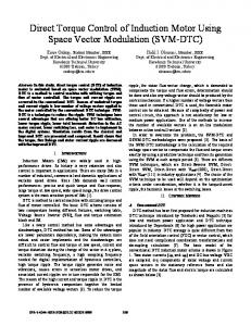
Fig. 1. Overview of speed-controlled induction motor drive using a direct rotor-field-oriented controller, a synchronous-frame current controller, and a random switching frequency pulsewidth modulator. As indicated, the sampling instants of the inner loops are synchronized to the random switching frequency, whereas the speed controller is updated at a fixed rate.
Fig. 1 defines the nomenclature and shows that the following issues have to be addressed. • Current Controller—The innermost loop contains the current controller that generates the reference voltage to the RPWM unit. The current controller is implemented in synchronous coordinates aligned with the rotor flux. The sampling is synchronized to the RPWM unit. Zero steady-state error and a high bandwidth are essential for good performance. • Motor Model—The motor model is also part of the inner loop and it is updated in every switching cycle. The model needed for the transformation estimates the position and coordinates and the amplitude of between the rotor flux. • Flux and Torque Control by FOC—The torque controller outputs the component of and the flux controller outputs the commanded -axis stator current. Both are calculated in rotor flux coordinates. • Speed Control and Flux Set Point—The outermost loop contains a speed controller and a flux set-point generator. The speed controller generates the reference torque; the flux level is set as a function of the speed reference. It may be noted that the system shown in Fig. 1 only contains the core components of a field-oriented drive as described in, e.g., [10]. No attempts have been made to implement advanced features like online estimation of the rotor time constant or the magnetizing inductance, which influence the accuracy of the estimation of the rotor flux and the developed torque. Nor is speedsensorless operation considered. Hence, it must be expected that the performance obtainable with the system used leaves plenty of room for the improvement of system-level performance. However, these secondary functions have not been considered due to the fact that the main objective of this paper is to demonstrate the possibilities of unifying a random pulsewidth modulator with commonly used feedback control techniques for ac drives.
III. RPWM AND CLOSED-LOOP CONTROL A. Review of Previous Work RPWM appeared for the first time in 1987 [11]. In the period 1987–1999, more than 100 papers dealing with RPWM have been published. In retrospect, it may be observed that all but three papers have dealt with open-loop voltage-controlled schemes without any feedback control involved. The exceptions are [8], [6], and [7], excluding a few almost identical companion papers. Reference [8] presents a current controller for an induction motor operating with random selection of the switching frequency and, furthermore, the updating of the proportional-plusintegral (PI)-type controller is synchronized to the RPWM unit. Since the sampling frequency of the PI controller is nonconstant, the coefficients of the governing difference equation are recalculated in every sampling period in order to approximate the response of the digital implementation to the response of the underlying analog PI controller independently of the instantaneous sampling rate. In short, [8] shows that RSF-PWM is compatible with standard principles for current control—at least for simple first-order compensators like PI controllers. Reference [7] aims at implementing a high-performance vector-controlled induction motor drive using a random switching technique, which the authors of [7] claim reduces the acoustic noise while still maintaining full rotor-field-oriented control. The correctness of these claims is questionable because no attention is paid to two serious defeats related to the RLL pulse position modulation technique adopted in [7]. First of all, it can easily be demonstrated by listening tests that RLL is about the worst RPWM technique regarding acoustic noise reduction—in fact, most people find the noise caused by RLL modulation more annoying than ordinary fixed-frequency PWM. Such simple tests have been used to support the conclusions given in [4] and [9]. The second serious defect of the RLL may be grasped by means of Fig. 2(a), which shows several characteristics of the RLL pulse position method. The switching
BECH et al.: FOC OF AN INDUCTION MOTOR USING RPWM
1779
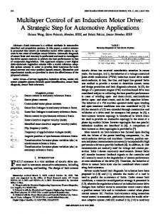
Fig. 2. Examples of switching functions (q ; q , and q ), ripple voltage u ~ and ripple current ~i , and the trajectory of ~i for (a) RLL, (b) random zero-vector, and (c) random switching frequency modulation. The reference voltage u used is the same for all three examples. See [9] for details.
functions are highly nonsymmetric and this deteriorates the quality of the phase current, i.e., a substantial nonsymmetrical ripple component [ in Fig. 2(a)] is generated by the RLL method. This makes error-free sampling of the fundamental component of the phase currents almost impossible. Also, as illustrated at the bottom of Fig. 2(a), the per-switching-cycle of the ripple current vector is nonzero, which average value implies that the RLL modulation process alters the fundamental component of the current besides causing substantial current ripple. The existence of these problems with the RLL is totally ignored in [7], which focuses solely on the constant switching frequency operation that makes closed-loop control simple once real-world concerns like current acquisition and quality are ignored. Sensorless vector control of an induction motor is reported in [6] and, again, an RPWM method operating with a constant switching frequency is used to avoid problems with the discrete-time controller. The RPWM principle in [6] randomizes the number of commutations within one switching period. This is done by modifying the usual sequence of switching states ( and are the
zero state vectors; and are the active vectors spanning the sector to which the reference belongs) giving six commutations in each switching period. Reference [6] proposes a method that gives either 6, 10, or 11 commutations in each switching interval depending on the outcome of a random experiment. This unusually large number of commutations is achieved by swapping the order of applications of states; an example is the se(ten quence commutations) suggested in [6]. Clearly, this forces the inverter to jump between nonadjacent states, where two inverter legs change state simultaneously. Such a situation is undesirable, as pointed out in [12]. Hence, increasing the switching losses is inevitable, but [6] does not comment on this problem either. Finally, the problem of sampling error-free phase currents is overlooked in [6] despite the fact that nonsymmetrical switching patterns are generated by some of the switching sequences suggested herein. In summary, [6] and [7] both demonstrate working RPWMbased FOC of an induction motor, but it is the opinion of the authors that the principles outlined in these papers leave room for many improvements.
1780
IEEE TRANSACTIONS ON INDUSTRY APPLICATIONS, VOL. 37, NO. 6, NOVEMBER/DECEMBER 2001
B. Important Issues in Closed-Loop Applications of RPWM Based on the authors’ own experiences with many RPWM schemes, including those reported in [9], and on the work of [8], [6] and [7], the following key issues for the successful use of RPWM in closed-loop applications like FOC may be listed. • Sampling of Phase Currents—Error-free acquisitions of the phase currents fed back to the controller are crucial for a satisfactory operation of the final system. • Controller Implementation—In high-performance systems, discrete-time algorithms are usually implemented in microcontrollers, DSPs, etc., which are updated every seconds. The inner loops are normally synchronized equals , where is the to the PWM unit, i.e., PWM switching frequency. • Overall System Performance—This includes speed and torque dynamics, current quality, and switching losses besides the main reason of introducing RPWM in the first place: the acoustic noise problem should be alleviated under all operating conditions. The first requirement restricts the pool of candidate RPWM methods to the techniques that preserve symmetry of the generated switching patterns around the center of the switching interval. The synchronization between, e.g., the current controller and the PWM unit does not directly impose constraints on the usable RPWM methods, although those methods operating at a fixed switching frequency are preferable. Then, all classic design methods based on the transformation can be used and the final discrete-time implementation becomes a simple difference equation with constants coefficients. For those RPWM schemes , the required that randomize the PWM switching frequency synchronization implies that the sampling interval of the controllers varies in an unpredictable manner. This random variamust be considered for a proper real-time evaluation tion in of the controller algorithms and, also, all the usual discrete-time design procedures fail. The third issue listed above should be self-explanatory: the randomized drive should have better subjective acoustic noise properties than the nonrandomized drive and, meanwhile, all tangible characteristics, like torque response, speed regulation, switching losses, and current quality, should remain unaffected by the randomization. C. Preferred RPWM Methods for Three-Phase Applications As elaborated above, nothing positive can be said about the RLL technique illustrated in Fig. 2(a) and used in [7]. The current quality is very poor and there is no improvement regarding the emitted acoustic noise. Hence, the RLL modulation cannot be recommended for practical use. The excessive losses associated with the method of [6] are clearly disadvantages of that scheme and, also, the effects on the current quality and the acoustic noise are either not commented upon nor convincingly documented in [6] or in any known companion papers. Until these issues have been addressed and shown to be acceptable, the RPWM method of [6] cannot be considered as a candidate for practical applications.
At the time of writing, the two most promising methods to randomize three-phase converters seem to be the following. • Random Zero-Voltage Vector Distribution (RZD)—In all three-phase three-wire systems, the duration of the zerovoltage component does not alter the phase voltages. This fact is utilized in the RZD method, where the division of the total available zero-vector time among vectors and is randomized; see Fig. 2(b) [13]. The switching frequency is constant. • RSF-PWM—The instantaneous switching frequency is randomly varied within some upper and lower bounds [2]–[5]. Fig. 2(c) shows some waveforms for this familiar technique. Besides the described characteristics, both methods guarantee transitions between adjacent states only—in fact, the order of application of the individual switching states is identical to the sequences produced by the well-known space-vector modulation. Another important property is the center alignment of all pulses within the switching period. This guarantees error-free sampling of the fundamental current component as illustrated , and in Fig. 2(b) and (c). at the time instants labeled The RZV method performs well with respect to the issues listed in Section III-B, except from the effectiveness on the acoustic noise for large values of the modulation index [9]. and When is large, the total duration of the zero vectors is small, leaving little room for the randomization. Notice how easy RZV may be incorporated into an existing FOC drive. Only minor modifications to the PWM unit are needed; the control algorithm remains unaffected by this particular kind of randomization due to the constant switching and sampling frequency. Considering the acoustic noise reduction, there is no doubt that RSF-PWM is the best-performing method, as stipulated already in Section I. RSF-PWM suppresses all power spectral components (for all values of ) in the converter output voltage except for the fundamental component, i.e., all the discrete harmonics normally peaking up around the switching frequency and its multiples are transformed into the continuous density spectrum. The major problem for RSF-PWM relates to the discretization and design of controllers, i.e., the interaction between the modulator and the rest of the control system needs further attention. The remaining part of this paper outlines how these problems with the design and implementation of a RSF-PWM-based FOC drive may be solved. IV. DESIGN CONSIDERATIONS A. Approaches to Digital Design Regarding design of digital systems (controllers, filters, estimators, observers, etc.), different routes may be followed from the performance specifications to the final discrete-time algorithm. Based on classic textbooks including [14]–[16], the design procedures may be divided into two top-level categories. • Indirect Digital Design—Initially, the design is performed in the continuous-time domain by ignoring that the controller must be implemented in a sampled-data system. has been determined, a When a transfer function
BECH et al.: FOC OF AN INDUCTION MOTOR USING RPWM
1781
discrete-time equivalent of is found by using some -to- mapping technique. • Direct Design in Discrete Time—The system model and the performance specifications are transformed into the domain before any detailed design is commenced. The design is then carried out in the domain; the difference equation for the final algorithm may be obtained directly from the discrete-time transfer function found. Now, the cardinal point is to recall that the sought implementation must be capable of operating with a nonuniform sampling rate. This implies that the direct design procedure using the transform is unsuitable for the application at hand. The whole framework of the transform is based on the fundamental requirement that the sampling instants are equally spaced in time. This leaves only the methods originating from the indirect design category as possible design procedures, but, again, not all of the methods available in textbooks like [14]–[16] are compatible with the nonuniform sampling requirement. Methods for discrete-time design by emulation of a continlike zero-pole mapping and uous-time transfer function hold equivalents (zero- and first-order, triangular) all involve transforms, which exclude their use in the present problem. Based on this brief review and the elaborated analysis in [17], it may be concluded that the only viable methods seem to be emulation methods that use some kind of numerical integration to into an algorithm suitable map a certain transfer function for real-time evaluation. B. Controller Algorithms Based on Numerical Integration The starting point for the design procedure given below is a for the filter or the contransfer function troller to be discretized. An equivalent state-space formulation of this input–output description may be obtained by standard methods, i.e., it may safely be assumed that the following repis known, too: resentation of
The value for is selected randomly in real time according for the samto the chosen probability density function pling interval (reciprocal of the switching frequency). may be either a continuous function [4] or a discrete function [18]. In the former case, an infinite number of different values are possible, but, in the latter case, only a finite number for are used to randomize the PWM of different values for switching frequency. The pool size may be as small as five without ruining the acoustic noise reduction [5], provided that certain measures against common multiples are taken [18]. Now, the following are considered. a matrix inversion of is required. • In order to update In general, this is a time-consuming operation because the number of multiplications goes up by the cube of the matrix dimension. can be put into a diagonal form with entries • If then by using , the inversion task simplifies sigdecouples the individual states nificantly. A diagonal and, then, the calculation of the matrix product only involves divisions. only attains a small number of different values, the • If matrix and can be precomputed and stored for and later real-time use. Then, online updates of are avoided completely. Even under these conditions, advantage of the diagonalization should be taken to limit the real-time computations further. It seems to be desirable that the system matrix in (2) is diagonal since this would result in much simpler calculations compared to the case where is nondiagonal. Fortunately, this has an infinity can be accomplished by recalling that any of state-space equivalents. Therefore, if is nondiagonal, it can be diagonalized by means of a similarity transformation [14], exists so that is diagonal. Then, (2) i.e., a matrix becomes
(1) (2)
(5)
and are vectors representing the controller input, Here, output, and internal states, respectively. The dimensions of the , and matrices depend on the system order. Although many numerical algorithms exist for integration of differential equations like (2), only a few of the simplest methods are applicable for discrete-time control systems: forward and backward Euler methods and the Tustin (bilinear, trapezoidal) integration rules. For linear systems, either the backward Euler or the bilinear method should be used due their better numerical properties. Using backward Euler, the dynamics of (2) may be approximated by
Space limitations prevent further details, but the main steps of the suggested procedure for design and implementation of nonuniformly sampled systems for real-time evaluation should be clear. • Offline Calculations—Determine the transfer function using conventional continuous-time techniques and so formulate a state-space description like (2). Find , and defined that is diagonalized and compute attains only a few known values, and by (4). If in (3) can be calculated offline, also. , update (if neces• Online Calculations—Given . Update the state vector sary) by and calculate the output by by Note that the matrix calculations are simpler than they appear because of the decoupling obtained by the diagonalization. Note also that other one-step approximations like the Tustin rule can also be applied.
(3) (4) where
is the unity matrix and is the epoch between the th and the th sampling instants.
(6)
1782
IEEE TRANSACTIONS ON INDUSTRY APPLICATIONS, VOL. 37, NO. 6, NOVEMBER/DECEMBER 2001
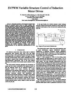
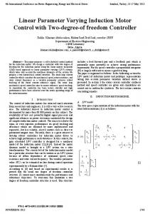
Fig. 3. Laboratory setup used for testing of the RPWM-based field-oriented controller.
TABLE I INDUCTION MOTOR RATINGS
TABLE II MOTOR PARAMETERS
V. EXPERIMENTAL RESULTS A. Field-Oriented Control System The system shown in Fig. 1 was initially designed in the continuous-time domain, and afterwards, discrete-time algorithms for the current controller (PI type with anti-integrator windup), the motor model (the open-loop “current model” in rotor-flux coordinates [10]), the FOC, and the speed controller (proportional–integral–derivative (PID)-type) were derived using the guidelines given above. Also, a third-order Butterworth low-pass filter having a 100-Hz corner frequency was implemented to attenuate measurement noise on the speed feedback signal. The current controller has a 500-Hz bandwidth. Detailed information may be found in [17]. B. Setup Laboratory measurements were performed using the setup shown in Fig. 3. The three-phase inverter rated at 4 kVA is fed from a diode rectifier through an LC filter. The key data of the 1.5 kW induction motor used are listed in Tables I and II. The motor is loaded by a dc generator connected to a variable-power resistor. The shaft speed is measured by an encoder with 2500 lines per revolution. All control and PWM generation are implemented in a combined 32-bit floating-point DSP (Analog Devices SHARC
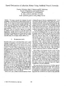
21 062) and a 16-bit fixed-point microcontroller (Siemens SAB C167) system. As shown in Fig. 1, the inner loops are sampled at a nonuniform time grid, while the speed controller operates at a fixed clock (400 Hz). Feedback signals including the phase currents, the dc-link voltage, and the shaft speed are acquired by simultaneous sampling and multiplexed analog-to-digital conversion (12-bit, 2.3- s conversion time/channel). For reasons of comparison, the test is performed for both the RSF-PWM and for the fixed switching frequency PWM. In the RSF-PWM mode, the switching/sampling frequency is selected randomly in the 4–6-kHz range in each PWM period using a uniform probability density function. The classic modulator operates at 5 kHz, i.e., the average switching frequency is equal for both cases. C. Results of Dynamic Tests In Fig. 4, sample test results are shown. Fig. 4(a)–(d) shows the response of the current controller to a step change of the -axis current from 1 to 2 A, while should be kept constant at 3 A. The figures verify that there are no significant differences between the results whether RPWM is used or not. Also, Fig. 4(e) and (f) shows that RPWM does not deteriorate the performance of the speed control loop at all during a ramping test. D. Steady-State Results Frequency-domain spectra were measured during steady-state operation using the Brüel & Kjær PULSE multi-analyzer. Power spectral densities for line-to-line voltage, phase current, and the emitted acoustic noise are shown in Fig. 5. For standard operation with fixed switching frequency, large spectral peaks occur at multiples of the switching frequency as seen in Fig. 5(a), (c), and (e). Subjectively, the sound emitted by the motor is very annoying under these conditions. The plots in Fig. 5(b), (d), and (f) show the result obtained under the same conditions, except for the random switching/sampling frequency operation. Now, the nonfundamental power is spread over a much wider frequency range, and the acoustic noise is much less annoying due to suppression of all the pure tones in the spectrum.
BECH et al.: FOC OF AN INDUCTION MOTOR USING RPWM
1783
Fig. 4. Measurements of dynamics using classic SVM with 5 kHz (top row) and random switching frequency 4–6 kHz (bottom row). (a), (b) Step change of the reference q -axis current at 5-Hz fundamental frequency. (c), (d) Step change of the reference q -axis current at 40-Hz fundamental frequency. (e), (f) Ramping of the reference speed from 300 to 2400 r/min.
Fig. 5.
Measurements of steady-state frequency spectra using classic SVM with 5 kHz (top row) and random switching frequency 4–6 kHz (bottom row). Settings: = 1 A; 5-Hz fundamental frequency. (a), (b) Power spectral density (PSD) of the line-to-line voltage. (c), (d) Power spectral density of the phase current. (e), (f) Power spectral density of the emitted acoustic noise.
i
= 3 A; i
1784
IEEE TRANSACTIONS ON INDUSTRY APPLICATIONS, VOL. 37, NO. 6, NOVEMBER/DECEMBER 2001
VI. CONCLUSION For the first time, it has been demonstrated that it is possible to unify RSF-PWM with field-oriented control of induction motors. By doing so, the good acoustic properties due to the random switching frequency operation can be seamlessly incorporated into high-performance drives with only minor computational overhead compared to nonrandomized PWM schemes. Laboratory tests verify that the dynamic responses obtained by RSF-PWM are almost indiscernible to the results recorded for fixed-frequency operation. Simultaneously, the power carried by the harmonics is transformed into the continuous density spectrum, making the drive much less annoying from an acoustic point of view. Comparing the methods and the results obtained in this paper to earlier reports dealing with RPWM in closed-loop systems [8], [6], [7], many enhancements have been obtained. A general design methodology for discrete-time implementation of arbitrary transfer functions (filters, controllers, etc.) based on nonuniform sampling rate case was verified by measurements; a total (although without any extraordinary features) field-oriented control system based on a RSF-PWM unit was designed, implemented, and then tested experimentally. The innermost loops (a current controller and a rotor-flux estimator) are synchronized to the random switching instants of the inverter. A slower speed-control loop is also implemented. The DTC technique does also address the acoustic noise problem, and [3] shows that DTC and RSF-PWM have similar frequency-domain characteristics regarding voltage, current, and emitted acoustic noise. The results reported in the present paper extend the similarity to include the dynamic performance of these two—conceptually very different—methods to control an ac machine. Still, the proposed system has the major advantage that the switching frequency is totally independent of the connected load, i.e., the current ripple and the average switching losses can be evaluated straightforwardly. For the DTC, the instantaneous switching frequency depends on tolerance bands of hysteresis controllers and on the motor in a complicated way. Finally, it should be emphasized that the use of RSF-PWM is by no means limited to the particular application investigated here. The ideas and the design methodology may easily be adapted to other applications where nonuniform sampling is required.
[5] G. A. Covic and J. T. Boys, “Noise quieting with random PWM AC drives,” Proc. IEE—Elect. Power Applicat., vol. 145, no. 1, pp. 1–10, Jan. 1998. [6] Y. S. Lai, “Sensorless vector-controlled IM drives using random switching technique,” in Proc. 8th European Conf. Power Electronics and Applications, Sept. 1999, CD-ROM. [7] B.-R. Lin and H.-H. Lu, “Three-phase AC/DC/AC converter with random pulse position,” in Proc. 8th European Conf. Power Electronics and Applications, Sept. 1999, CD-ROM. [8] C. B. Jacobina, A. M. N. Lima, E. R. C. da Silva, and R. L. de A. Ribeiro, “Current control for a random PWM voltage source inverter,” in Proc. IEEE PESC’97, vol. 2, 1997, pp. 1440–1446. [9] M. M. Bech, F. Blaabjerg, and J. K. Pedersen, “Random modulation techniques with fixed switching frequency for three-phase power converters,” IEEE Trans. Power Electron., vol. 15, pp. 753–761, July 2000. [10] M. P. Kaz´mierkowski and H. Tunia, Automatic Control of Converter-Fed Drives, Studies in Electrical and Electronic Engineering 45. Amsterdam, The Netherlands: Elsevier, 1994. [11] A. M. Trzynadlowski, S. Legowski, and R. L. Kirlin, “Random pulse width modulation technique for voltage-controlled power inverters,” in Conf. Rec. IEEE-IAS Annu. Meeting, 1987, pp. 863–868. [12] H. W. Van der Broeck, H. C. Skudelny, and G. V. Stanke, “Analysis and realization of a pulsewidth modulator based on voltage space vectors,” IEEE Trans. Ind. Applicat., vol. 24, pp. 142–150, Jan./Feb. 1988. [13] V. Blasko, “Analysis of a hybrid PWM based on modified space-vector and triangle-comparison methods,” IEEE Trans. Ind. Applicat., vol. 33, pp. 756–764, May/June 1997. [14] K. Ogata, Discrete-Time Control Systems. Englewood Cliffs, NJ: Prentice-Hall, 1987. [15] K. J. Åström and B. Wittenmark, Computer-Controlled Systems. Theory and Design. Englewood Cliffs, NJ: Prentice-Hall, 1990. [16] G. F. Franklin, J. D. Powell, and M. L. Workman, Digital Control of Dynamic Systems, 2nd ed. Reading, MA: Addison-Wesley, 1990. [17] M. M. Bech, “Random pulse-width modulation techniques for power electronic converters,” Ph.D. dissertation, Aalborg Univ., Aalborg East, Denmark, Aug. 2000. [18] A. M. Trzynadlowski, M. M. Bech, F. Blaabjerg, J. K. Pedersen, R. L. Kirlin, and M. Zigliotto, “Optimization of switching frequencies in the limited-pool random space vector PWM technique for inverter-fed drives,” in Proc. IEEE APEC’99, vol. 2, 1999, pp. 1013–1018.
Michael M. Bech (S’95–M’00) was born in Denmark in 1971. He received the M.Sc. and Ph.D. degrees in electrical engineering from Aalborg University, Aalborg East, Denmark, in 1995 and 2000, respectively. Since 1995, he has been with the Institute of Energy Technology, Department of Electrical Energy Conversion, Aalborg University, where he currently is an Assistant Professor. His main research area is the analysis of pulsewidth modulation techniques for static power converters. Other areas of interest include power electronic converters and their applications to ac drives and uninterruptible power supplies. Mr. Bech is a member of the IEEE Industry Applications, IEEE Power Electronics, and IEEE Industrial Electronics Societies.
REFERENCES [1] K. Ohnishi, N. Matsui, and Y. Hori, “Estimation, identification, and sensor-less control of AC drives,” in Power Electronics and Variable Frequency Drives. Technology and Applications, B. K. Bose, Ed. New York: IEEE Press, 1997, pp. 454–479. [2] T. G. Habetler and D. M. Divan, “Acoustic noise reduction in sinusoidal PWM drives using a randomly modulated carrier,” IEEE Trans. Power Electron., vol. 6, pp. 356–363, July 1991. [3] L. Xu, Z. Q. Zhu, D. Stone, and D. Howe, “Acoustic noise radiated by space vector PWM, random PWM and direct torque controlled induction motor drives,” in Proc. Int. Conf. Electric Machines, vol. 3, 1998, pp. 1746–1751. [4] M. M. Bech, F. Blaabjerg, J. K. Pedersen, and A. M. Trzynadlowski, “Comparative investigation of random PWM techniques with variable switching frequency and pulse position for inverter-fed induction motors,” in Proc. 7th European Conf. Power Electronics and Applications, vol. 1, 1997, pp. 343–349.
John K. Pedersen (M’91–SM’00) was born in Holstebro, Denmark, in 1959. He received the B.Sc.EE. degree from Aalborg University, Aalborg East, Denmark. In 1983, he joined the Institute of Energy Technology, Aalborg University, as a Teaching Assistant. He became an Assistant Professor in 1984 and, since 1989, he has been an Associate Professor. He is also currently the Head of the Institute of Energy Technology. His research areas are power electronics, power converters, and electrical drive systems, including modeling, simulation, and design with a focus on optimized efficiency. Mr. Pedersen received the 1992 Angelos Award for his contribution to the control of induction machines. In 1998, he received an IEEE TRANSACTIONS ON POWER ELECTRONICS Prize Paper Award for the best paper published in 1997.
BECH et al.: FOC OF AN INDUCTION MOTOR USING RPWM
Frede Blaabjerg (S’86–M’88–SM’97) was born in Erslev, Denmark, in 1963. He received the Msc.E.E. degree from Aalborg University, Aalborg East, Denmark, and the Ph.D. degree from the Institute of Energy Technology, Aalborg University, in 1987 and 1995, respectively. He was with ABB-Scandia, Randers, Denmark, from 1987 to 1988. He joined Aalborg University in 1992 as an Assistant Professor. In 1996, he became an Associate Professor and, in 1998, he became a Full Professor of power electronics and drives. His research areas are power electronics, static power converters, ac drives, switched reluctance drives, modeling, characterization of power semiconductor devices, and simulation. He is involved in more than 15 research projects with industry. Among them is the Danfoss Professor Programme in Power Electronics and Drives. He has authored more than 200 publications in his research fields. He is an Associate Editor of the Danish journal Elteknik. He serves as a member of the Danish Technical Research Council in Denmark and as a member of the board of the Danish Space Research Institute. Dr. Blaabjerg is a member of the European Power Electronics and Drives Association. He is also a member of the Industrial Drives, Industrial Power Converter, and Power Electronics Devices and Components Committeess of the IEEE Industry Applications Society. He is an Associate Editor of the IEEE TRANSACTIONS ON INDUSTRY APPLICATIONS. He became a member of the Danish Academy of Technical Science in 2001. He received the 1995 Angelos Award for his contribution to modulation technique and control of electric drives, and an Annual Teacher Prize from Aalborg University, also in 1995. In 1998, he received the Outstanding Young Power Electronics Engineer Award from the IEEE Power Electronics Society and an IEEE TRANSACTIONS ON POWER ELECTRONICS Prize Paper Award for the best paper published in 1997. Finally, he received two Prize Paper Awards at the IEEE Industry Applications Society Annual Meeting in 1998.
1785