Renesas Technology Corp., Japan. Abstract. The parallel branching program machine (PBM128) consists of 128 branching program machines (BMs) and a ...
A Parallel Branching Program Machine for Emulation of Sequential Circuits Hiroki Nakahara1, Tsutomu Sasao1 Munehiro Matsuura1 , and Yoshifumi Kawamura2 1
Kyushu Institute of Technology, Japan Renesas Technology Corp., Japan
2
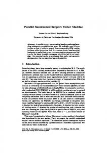
Abstract. The parallel branching program machine (PBM128) consists of 128 branching program machines (BMs) and a programmable interconnection. To represent logic functions on BMs, we use quaternary decision diagrams. To evaluate functions, we use 3-address quaternary branch instructions. We emulated many benchmark circuits on PBM128, and compared its memory size and computation time with the Intel’s Core2Duo microprocessor. PBM128 requires approximately quarter of the memory for the Core2Duo, and is 21.4-96.1 times faster than the Core2Duo.
1 Introduction A Branching Program Machine (BM) is a special-purpose processor that evaluates binary decision diagrams (BDDs)[3,2,14]. The BM uses only two kind of instructions: Branch and output instructions. Thus, the architecture for the BM is much simpler than that for a general-purpose microprocessor (MPU). Since the BM uses the dedicated instructions to evaluate BDDs, it is faster than the MPU. In fact, for control applications, the BM is much faster than the MPU [2]. The applications of BMs include sequencers [3,14], logic simulators [11,1], and networks (e.g., packet classification). In this paper, we show the parallel branching machine (PBM128) that consists of 128 BMs and a programmable interconnection. To reduce computation time and memory size, we use special instructions that evaluate consecutive two nodes at a time.
2 Branching Program Machine to Emulate Sequential Circuits We show the branching program machine (BM) that emulates the sequential circuit shown in Fig. 1. First, the combinational circuit is represented by a decision diagram. Next, it is translated into the codes of the BM. Finally, the BM executes those codes. To emulate the sequential circuit, the BM uses registers that store state variables. We assume that the BM uses 32-bit instructions, which match the data structure of embedded systems and the embedded memory of FPGAs. 2.1 MTQDD In this paper, we use standard terminologies for reduced ordered binary decision diagrams (BDDs)[4], and reduced ordered multi-valued decision diagrams (MDDs)[9]. J. Becker et al. (Eds.): ARC 2009, LNCS 5453, pp. 261–267, 2009. c Springer-Verlag Berlin Heidelberg 2009 �
262
H. Nakahara et al.
Combinatioanl Circuit
FF
External Outputs State Inputs
...
...
State Outputs
...
...
External Inputs
Fig. 1. Model for a Sequential Circuit A0
0 A1
1
A7
1
A4
10
DATASET DATA,REG,ADDR 16 15 31 29 24 23 ADDR 10 REG
0
A5
A6
00
Fig. 3. Example of MTBDD
X0={x0, x1}
A0 00
01 10
11
A2 00 01 10
x3
1
DATA
Fig. 2. Mnemonics and Internal Representations
0 0
01
0
x2
A8
1
0 A2
B_BRANCH (ADDR0,ADDR1),INDEX 16 15 8 7 31 29 28 22 21 ADDR0 ADDR1 INDEX 111
x1
1
0 A3
0
x0
1 0
Q_BRANCH (ADDR0,ADDR1,ADDR2),INDEX,SEL 16 15 8 7 3130 26 2524 23 ADDR0 ADDR1 ADDR2 0 INDEX SEL
A1
A3
01
A5 11
X1={x2, x3}
10 00 01 11 A4
10
00
Fig. 4. MTQDD derived from MTBDD in Fig. 3
An MTBDD (Multi-Terminal Binary Decision Diagram) [8] can evaluate many outputs at a time. Evaluation of an MTBDD requires n table look-ups. The APL (average path length) of a BDD denotes the average number of nodes to traverse for the BDD. Evaluation time for a BDD is proportional to the APL [5]. To further speed up the evaluation, an MTMDD(k) (Multi-terminal Multi-valued Decision Diagram) is used. In the MTMDD(k), k variables are grouped to form a 2k -valued super variable. Note that a BDD is equivalent to an MDD(1). For many benchmark functions, in logic evaluation, with regard to the area-time complexity, MDD(2)s are more suitable than BDDs. Since MDD(2) has 4 branches, it is denoted by a QDD (Quaternary Decision Diagram). In this paper, we use an MTQDD (Multi-terminal Multi-valued QDD). Example 2.1 Fig. 3 shows an example of MTBDD. Fig. 4 shows the MTQDD that is derived from the MTBDD in Fig. 3. (End of Example) 2.2 Instructions to Evaluate MTQDDs Three types of instructions are used to evaluate an MTQDD. A 2-address binary branch instruction (B BRANCH) and a 3-address quaternary branch instruction (Q BRANCH) evaluate a non-terminal node, while a dataset instruction (DATASET) evaluates a terminal node. Mnemonics and their internal representations for B BRANCH, Q BRANCH and DATASET are shown in Fig. 2. B BRANCH performs a binary branch: If the value of the variable specified by INDEX is equal to 0, then GOTO ADDR0, else GOTO ADDR1. DATASET performs an output operation and a jump operation. First, DATASET writes DATA (16 bits) to
A Parallel Branching Program Machine for Emulation of Sequential Circuits
263
a register specified by REG. Then, GOTO ADDR. Q BRANCH jumps to one of four addresses: Three jump addresses are specified by ADDR0, ADDR1, and ADDR2, while the remaining address is the next address (PC+1) to the present one. Since it evaluates two variables at a time, the total evaluation time is reduced up to a half of a B BRANCH instruction. Also, it can reduce the total number of instructions. We use four different Q BRANCH instructions shown in Fig. 7. SEL in the Q BRANCH specifies one of four combinations. Let i be the value of the variable specified by INDEX. If (SEL=i), then jump to PC+1, otherwise jump to ADDRi . In addition, unconditional jump instructions are necessary to evaluate some QDDs. Example 2.2 illustrates this. Example 2.2 The program in Fig. 5 evaluates the MTBDD in Fig. 3. Consider the MTQDD shown in Fig. 4. Fig. 8 shows the MTQDD with address assignment for Q BRANCH instructions, where SEL has the same meaning as Fig. 7. For A6, B BRANCH instruction is used to perform an unconditional jump. The program in Fig. 6 evaluates the MTQDD. (End of Example) A0: A1: A2: A3: A4: A5: A6: A7: A8:
B BRANCH (A1,A7),x0 B BRANCH (A2,A3),x1 DATASET 01,0,A0 B BRANCH (A4,A5),x2 DATASET 10,0,A0 B BRANCH (A4,A6),x3 DATASET 00,0,A0 B BRANCH (A3,A8),x1 B BRANCH (A6,A5),x2
Fig. 5. Program Code for the MTBDD in Fig. 3 SEL=00 xi xi+1
A0: A1: A2: A3: A4: A5: A6:
Q BRANCH (A2,A2,A5),X0,00 DATASET 01,0,A0 Q BRANCH (A3,A3,A4),X1,00 DATASET 10,0,A0 DATASET 00,0,A0 Q BRANCH (A4,A4,A4),X1,10 B BRANCH (A3,A3),--
Fig. 6. Program Code for the MTQDD in Fig. 8
SEL=01 xi xi+1
00
A0 SEL=00 01 10
00 01 10 11 00 01 10 11 PC+1 ADDR0 ADDR1 ADDR2 ADDR0 PC+1 ADDR1 ADDR2
SEL=10 xi xi+1 00
A2 SEL=00
SEL=11 xi xi+1 01 10 11
ADDR0 ADDR1 PC+1 ADDR2
00
X0={x0, x1} 11
00 01 10
01 10 11
ADDR0 ADDR1 ADDR2 PC+1
Fig. 7. Four Different Q BRANCH Instructions
A1
A3
01
11
10
A5 X ={x2, x3} SEL=10 1 00 01 11
A6 A4
10 00 unconditional jump
Fig. 8. MTQDD with 3-address Quaternary Branch Instructions
2.3 Branching Program Machine for a Sequential Circuit Fig. 9 shows a branching program machine (BM) for a sequential circuit. It consists of the instruction memory that stores up to 256 words of 32 bits; the instruction decoder; the program counter (PC); and the register file. In our implementation, two clocks are used to execute each instruction of the BM: A Double-Rank Filp-Flop is used to implement the state register and the output register [12]. Fig. 10 shows the Double-Rank Filp-Flop, where L1 and L2 are D-latches.
H. Nakahara et al.
Selector Instruction Memory
(32bit x 256word)
register file
PC
To Next BM
External Outputs
External Inputs (From MPU)
From previous BM
264
select
L1
Instruction Dec.
L2
MUX
Instruction reg.
S_Clock
Fig. 10. Double-Rank Flip-Flop
Fig. 9. BM for a Sequential Circuit
In the BM, values of state register are feedbacked into its inputs. Thus, the BM can emulate a sequential circuit. A BM can load the external inputs, the state variables, and the outputs from other BMs by specifying the value of the input select register.
3 Parallel Branching Program Machine 3.1 8 BM Fig. 11 shows the architecture of the 8 BM consisting of 8 BMs. The output registers and the flag registers of BMs are connected in cascade through programmable routing boxes. Then, these values are stored into the common registers of the 8 BM. Also, the values of registers are feedbacked to the input of BM0 . Each BM can operate independently. A programmable routing box implements either the bitwise AND, or the bitwise OR operation. Constant values can be also generated. In the programmable routing boxes (highlighted with gray in Fig. 11), constant 1s are generated to perform the bitwise AND operation, while constant 0s are generated to perform the bitwise OR operation. Since BMs are connected each other by sharing a register, each BM can send the signal to other BM in one clock. Since a BM uses two clocks to perform an instruction, the communication delay within an 8 BM can be neglected. Ext. Inputs
Ext. Outputs
MPU
BM_7
Configuration Sig.
System Bus
BM_1
reg.
Programmable Routing Box
BM_0
in out
in out
in out
8_BM_0
8_BM_1
8_BM_15
state var.
state var.
state var.
Programmable Interconnection Programmable Interconnection
Fig. 11. Architecture of 8 BM
Fig. 12. Parallel Branching Program Machine (PBM128)
A Parallel Branching Program Machine for Emulation of Sequential Circuits
265
3.2 Parallel Branching Program Machine Fig. 12 shows the Parallel Branching program Machine (PBM128) consisting of 128 BMs described in Section 2. Eight BM constitute an 8 BMs, and sixteen 8 BMs and a programmable interconnection constitute the PBM128. Primary inputs and configuration signals are sent to the 8 BMs. Each 8 BM has external outputs and state variables. The external outputs are connected to the system bus, while the state variables are sent to 8 BMs through the programmable interconnection. When the all 8 BMs finish the operation, the values of state variables of an 8 BM are sent to other 8 BMs through the programmable interconnection. These operations can be specified by the values of the flag register. In addition, MPU is used to control the whole system. 3.3 Programmable Interconnection A multi-level circuit of multiplexers is used in the programmable interconnection. To increase the throughput, pipeline registers are inserted into the programmable interconnection. The insertion of pipeline registers increases the latency: Four clocks are used to connect the outputs of an 8 BM to other 8 BM. Since two clocks are used for an instruction of the BM, the PBM128 requires two instructions time to finish the connection between BMs in different 8 BMs. In the code generation, the wait time inserted.
4 Implementation and Experimental Results 4.1 Implementation of Parallel Branching Program Machine We implemented the PBM128 on the Altera’s FPGA (StratixII: EP2S130F1508C4). In our implementation, the maximum frequency is 132.73[MHz]. The PBM128 consumes 67817 ALUTs out of 106032 of available ALUTs. Each BM consumes 455 ALUTs (0.6% of used ALUTs), each 8 BM consumes 3778 ALUTs (5.6% of used ALUTs), sixteen 8 BMs consume 60764 ALUTs (89.6% of used ALUTs), and the programmable interconnection consumes 6307 ALUTs (9.3% of used ALUTs). As for the MPU, the embedded processor NiosII/f is used. Table 1. Comparison of the Execution Code Size and the Execution Time Name In Out FF Core2Duo Code Time s5378 35 49 164 74.6 12030 s9234 36 39 211 148.6 13450 dsip 229 197 224 112.1 17500 bigkey 263 197 224 149.5 19170 apex6 135 99 23.0 3700 cps 24 102 33.9 3468 des 256 245 123.1 16560 frg2 143 139 40.0 6390
PBM128 Code Time 17.8 323 33.4 352 24.8 182 33.9 220 4.8 163 8.3 162 30.7 308 9.2 215
Ratio(C2D/PBM) Code Time 4.19 37.2 4.44 38.2 4.52 96.1 4.41 87.1 4.79 22.6 4.08 21.4 4.00 53.7 4.34 29.7
266
H. Nakahara et al.
4.2 Experimental Results We selected benchmark functions [13], and compared the execution time and code size for the PBM128 with the Intel’s general-purpose processor Core2Duo U7600 (1.2GHz, Cache L1 data 32KB, L1 instruction 32KB, and L2 2MB). The execution code was generated by gcc compiler with optimization option -O3. We partition the outputs into groups, then represent them by multiple MTQDDs, and finally convert them into the codes for the PBM128. We used a grouping method [10] that partitions outputs with similar inputs. As for the data structure, the MTQDD is used for the PBM128, while the MTBDD is used for the Core2Duo, since the MTBDD is faster than the MTQDD. We used the same partitions of the outputs in the Core2Duo and in the PBM128. To obtain the execution time per a vector, we generated random test vectors, and obtained the average time. The frequency for the PBM128 is 100[MHz], while that for the Core2Duo is 1.2[GHz]. Table 1 compares the code size and the execution time for the Core2Duo and the PBM128. In Table 1, Name denotes the name of benchmark function; In denotes the number of inputs; Out denotes the number of outputs; FF denotes the number of state variables; Code denotes the size of execution code [KBytes]; Time denotes the execution time [nsec]; and Ratios denote that for the code size and that of the execution time (Core2Duo/PBM128). Table 1 shows that the PBM128 requires approximately quarter of the memory for the Core2Duo, and is 21.4-96.1 times faster than the Core2Duo.
5 Conclusion In this paper, we presented the PBM128 that consists of 128 BMs and a programmable interconnection. To represent logic functions on BMs, we used quaternary decision diagrams. To evaluate functions, we used 3-address quaternary branch instructions. We emulated many benchmark functions on the PBM128 and the Intel’s Core2Duo microprocessor. The PBM128 requires approximately quarter of the memory of the Core2Duo, and is 21.4-96.1 times faster than the Core2Duo.
Acknowledgments This research is supported in part by the Grants in Aid for Scientific Research of JSPS, and the grant of Innovative Cluster Project of MEXT (the second stage). Discussion with Mr.Hisashi Kajiwara was quite useful.
References 1. Ashar, P., Malik, S.: Fast functional simulation using branching programs. In: Proc. International Conference on Computer Aided Design, pp. 408–412 (November 1995) 2. Baracos, P.C., Hudson, R.D., Vroomen, L.J., Zsombor-Murray, P.J.A.: Advances in binary decision based programmable controllers. IEEE Transactions on Industrial Electronics 35(3), 417–425 (1988)
A Parallel Branching Program Machine for Emulation of Sequential Circuits
267
3. Boute, R.T.: The binary-decision machine as programmable controller. Euromicro Newsletter 1(2), 16–22 (1976) 4. Bryant, R.E.: Graph-based algorithms for boolean function manipulation. IEEE Trans. Compt. C-35(8), 677–691 (1986) 5. Butler, J.T., Sasao, T., Matsuura, M.: Average path length of binary decision diagrams. IEEE Trans. Compt. 54(9), 1041–1053 (2005) 6. Clare, C.H.: Designing Logic Systems Using State Machines. McGraw-Hill, New York (1973) 7. Davio, M., Deschamps, J.-P., Thayse, A.: Digital Systems with Algorithm Implementation, p. 368. John Wiley & Sons, New York (1983) 8. Iguchi, Y., Sasao, T., Matsuura, M.: Evaluation of multiple-output logic functions. In: Asia and South Pacific Design Automation Conference 2003, Kitakyushu, Japan, January 21-24, pp. 312–315 (2003) 9. Kam, T., Villa, T., Brayton, R.K., Sagiovanni-Vincentelli, A.L.: Multi-valued decision diagrams: Theory and Applications. Multiple-Valued Logic 4(1-2), 9–62 (1998) 10. Nakahara, H., Sasao, T., Matsuura, M.: A Design algorithm for sequential circuits using LUT rings. IEICE Transactions on Fundamentals of Electronics, Communications and Computer Sciences E88-A(12), 3342–3350 (2005) 11. McGeer, P.C., McMillan, K.L., Saldanha, A., Sangiovanni-Vincentelli, A.L., Scaglia, P.: Fast discrete function evaluation using decision diagrams. In: Proc. International Conference on Computer Aided Design, pp. 402–407 (November 1995) 12. Sasao, T., Nakahara, H., Matsuura, M., Iguchi, Y.: Realization of sequential circuits by lookup table ring. In: The 2004 IEEE International Midwest Symposium on Circuits and Systems, Hiroshima, July 25-28, pp. I:517–I:520 (2004) 13. Yang, S.: Logic synthesis and optimization benchmark user guide version 3.0. MCNC (January 1991) 14. Zsombor-Murray, P.J.A., Vroomen, L.J., Hudson, R.D., Tho, L.-N., Holck, P.H.: Binarydecision-based programmable controllers, Part I-III. IEEE Micro 3(4), 67–83 (Part I), (5), 16–26 (Part II), (6), 24–39 (Part III) (1983)