present how VDCE can be used as a problem solving environment and how the users .... On the other hand, application development tools and environments ...
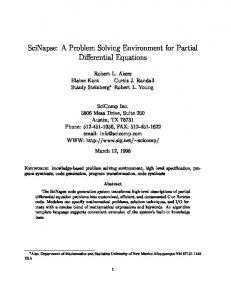
A Problem Solving Environment for Network Computing� Salim Hariri, Haluk Topcuoglu, Wojtek Furmanski, Dongmin Kim, Yoonhee Kim, Ilkyeun Ra, Xue Bing, Bouqing Ye, Jon Valentey
Dept. of Electrical Engineering and Computer Science HPDC Laboratory Syracuse University, Syracuse, NY 13244-4100 yRome Laboratory, Rome, NY A chapter in Problem Solving Environments book, edited by E. Houstis, R. Bramley, and E. Gallopoulos, to be published by IEEE Computer Society in 1997.
Abstract The current advances in high-speed networks and WWW technologies have made network computing a cost-e�ective high performance computing environment. New software development models and problem solving environments must be developed to utilize the network computing environment e�ciently. In this paper we present Virtual Distributed Computing Environment (VDCE), which provides a problem solving environment for high-performance distributed computing over wide-area networks. VDCE enables scientists to develop distributed applications without knowing the detailed architecture of the underlying resources. VDCE provides well-de ned library functions that relieve end users from tedious task implementations and it supports software reusability. The VDCE software architecture consists of two modules: Application Editor, and VDCE Runtime System. Application Editor is a Web-based graphical user interface that helps user to develop network applications and speci es the computing and communication properties of each task within the applications. The VDCE Runtime System schedules the individual tasks of the application to the best available resources, runs, and manages the application execution on the assigned resources. We also present how VDCE can be used as a problem solving environment and how the users can experiment and evaluate the performance of their applications for di�erent VDCE hardware and/or software con gurations. �
This research is supported by Rome Lab contract number F30602-95-C-0104.
1
1 Introduction The current advances in networking protocols (including ATM and Fast Ethernet), software development tools, and emerging WWW technologies have enabled the development of a cost-e�ective, high-performance distributed computing environment, network-based computing [1]. The network-based computing (or network computing (NC)) environment can provide the computational and storage requirements for solving large scale applications that used to run only on massively parallel processors and supercomputers. The available software tools for an high-performance computing environment still requires detailed understanding of the underlying architecture and the components of the application. Writing a parallel/distributed program overwhelms most of the users due to the complexity of communication and synchronization issues. Therefore, over the last few years, a number of application development and representing tools have become available to relieve users from this tedious process, including Code [2], HeNCE [3], and Zoom [3, 4], which are all graph-based programming environments. The graph representation of parallel programming simpli es programming, debugging, and visualization phases. However, most of these tools do not provide users the ability to experiment and evaluate the parallel/distributed programs with di�erent underlying software and hardware components. There is a growing interest to combine the computational and storage resources that are available over the Internet or over high speed networks (i.e VBNS, NYNET testbed) which provides a new computing environment, called metacomputing. In this paper, we present an overview of the Virtual Distributed Computing Environment (VDCE), a metacomputing environment that is currently being developed at Syracuse University. We also present how VDCE can be used as a problem solving environment for large scale network applications. Our problem solving environment enables users to focus on the solution approach to the problem rather than worrying about the parallel/distributed computing and network implementation issues. The software architecture of the VDCE problem solving environment has a web-based graphical user interface, called Application Editor, to develop parallel/distributed network applications and evaluate the application performance for the di�erent combinations of hardware/software tools. The Application Editor provides menu-driven functional building blocks of task libraries for building high performance distributed computing applications. VDCE Application Editor provides a large set of task libraries grouped in terms of their functionality, such as matrix algebra library, C 3I (command and control applications) library. By providing these functional building blocks, VDCE addresses the reusability issue of the problem solving environments. The visualization capability to show the performance for di�erent hardware/software con gurations is another important feature of the Application Editor. Once the application is designed/developed using the Application Editor, VDCE Runtime System is invoked to schedule, to run and to manage the execution of the application in a transparent manner. The VDCE Runtime System is responsible for task-to-resource 2
mapping, monitoring the VDCE resources, setting up the execution environment for a given application, monitoring the execution of the application tasks on the assigned computers, and maintaining the performance, fault tolerance, and quality of service (QoS) requirements. The rest of the paper is organized as follows. Section 2 introduces the issues of software development process for network-based computing and related work. In Section 3, we present an overview of VDCE and its applicability as a problem solving environment. In Section 4, we demonstrate through several examples how VDCE can be used to easily develop distributed applications as well as experiment and evaluate their performance. Concluding remarks are given in Section 5.
2 Software Development Issues and Stages Software development in any high performance (parallel/distributed) computing environment is a non-trivial process and requires a through understanding of the application and the underlying computer architecture [10]. The software development process is described as a set of stages which correspond to the phases encountered by a developer. Each stage requires di�erent kinds of supports, such as portable application description/design support, program implementation and run-time support, visualization support and reusability support. The stages in the process, which forms a development pipeline, are: Application Design and Speci cation Stage, Application Con guration and Scheduling Stage, Application Execution and Runtime Stage.
2.1 Application Design and Speci cation Stage.
The software development process considers two types of application development. � \New" Application Development: This class of applications involves solving new problems that require developers to start from scratch using a textual description of the problem or some means of formal and/or informal application speci cations techniques. � Porting of Exiting Applications (Dusty-Decks): This class includes developers attempting to port and update the existing codes written. In this stage, the application is speci ed (represented) in the form of a functional ow description of the application and its computation and communications requirements. Each node (termed as functional module) in the functional ow diagram is a black-box and contains information about (1) its input(s), (2) the function to be performed, (3) the desired output(s) and (4) the requirements at each node. The output of this stage is a detailed process ow graph where the nodes represent the functional components and the edges represent interdependencies. 3
Designing and implementing parallel/distributed programs overwhelms most users due to the di�culty of expressing communication and synchronization among the computations [5]. Some text-based parallel programming environments support the data parallel paradigm, which requires advanced compilation techniques and compilers. Most of the other environments require explicit insertion of communication and synchronization primitives within the programs, which makes parallel programs di�cult to understand. However, a graph-based programming environment provides simple and easy-to-use mechanisms for expressing the interaction of multiple threads within a parallel program [5]. In a graph-based programming environment (or graph-based application development tool), a program is de ned as a directed graph where nodes denote computations and links denote communication and synchronization between nodes [6]. The graph representation of parallel programming simpli es programming, debugging, and visualization phases. Over the last few years a number of graph-based application development and representation tools have become available, including Code [2], HeNCE [3], and Zoom [3, 4]. However, most of these tools do not provide users the ability to experiment and evaluate the generated parallel/distributed programs with di�erent underlying software and hardware components, di�erent implementation techniques, interconnection networks and message-passing tools. On the other hand, application development tools and environments supports webbased user interfaces; since World Wide Web is becoming a low-cost standard interface mechanism [7] to access the computational resources that are distributed all over the world. The Application Editor module of VDCE (which is explained in Section 3.) is a web-based graphical user interface for designing/specifying parallel and distributed applications. It provides a menu-driven functional building blocks of task libraries, which addresses the reusability issue of the software development process.
2.2 Application Con guration and Scheduling Stage
The application development stage receives the application speci cations (in terms of application ow graph or another speci cation syntax). This stage determines the hardware and software requirements of the application by interpreting the application speci cations and assigns current best available resources for running the application tasks in order to minimize the total execution time. This stage includes mapping module and estimation module. The mapping module has two consecutive parts according to it hierarchy: domainmapping part, resource-mapping part. The information provided by application design and development stage is used to map the functional components of the application to the domain by domain-mapping part and speci cally appropriate computing elements (or processors) by resource-mapping part. Both parts of this module use estimation module to get feedback for selecting between the existing candidates. Estimation Module is a critical component of the application development stage. This module evaluates di�erent options available and identi es the option that provides the best 4
performance. Estimation Module receives information about the hardware con guration, application ow information/requirements and the possible mappings. Then it estimates the performance of each mapping scheme and identi es the one which gives the best performance. Since the general form of scheduling problem is NP-hard, researchers have been working on near-optimal scheduling decisions. The research in this area has produced many di�erent types of scheduling algorithms (i.e, static, dynamic, centralized, distributed, etc.). Most of these algorithms are not general; instead they are targeted for speci c application and speci c resource types. There are some research projects that target application-level resource allocation issues such as APPLeS [9], and MARS [8] projects. VDCE provides application-based scheduling algorithm that runs on VDCE Server at each site. The required parameters of scheduling include task-speci c, resource-speci c, and user-speci c parameters, which are stored in the site repositories. The task scheduling approach is based on developing e�cient techniques to predict the performance of each task execution on each existing VDCE computing resource. Furthermore, our resource allocation approach is e�cient, since it uses a combination of performance analysis and measurement and benchmarking techniques to estimate the execution time of a task running on any VDCE computing platform under network contention and varying load conditions.
2.3 Application Execution and Run-Time Stage.
This stage handles the task of executing the developed and con gured application and produce the required output. The runtime stage integrates the assigned resources that will be involve in execution, and supports inter-module communications, which is based on either a message-passing tool such as PVM, p4, MPI, NCS or a distributed shared memory (DSM). During the execution of the application, this stage accepts data from di�erent computing elements and combines them for proper visualization. It intercepts the error messages generated and provides proper interpretation. The runtime system handles dynamic load-balancing, application and resource-level fault tolerance capabilities. Most of these functionalities are provided by VDCE Runtime System, which is the kernel of our problem solving environment. VDCE Runtime System is explained in Section 3. VDCE allows an end user to experiment and evaluate his/her application for the di�erent combinations of hardware and software medium. VDCE gives user the ability to select any message passing tool (NCS, P4, PVM, etc) and to select the types of network (Ethernet, ATM etc) to connect the computing resources.
3 Overview of VDCE The objective of the Virtual Distributed Computing Environment is to provide a general software development environment to design and construct large scale HPDC applications 5
on a network of heterogeneous computers.As a problem-solving environment, VDCE provides users with a set of task libraries to solve one class of applications. These task libraries can be used to compose any HPDC application as an application ow graph. VDCE is composed of geographically distributed computation sites, each of which runs its own VDCE Server. An end user views the underlying VDCE resources, interconnected by a global wide area network, as a single seamless computation resource (see Figure 1). The VDCE Server functions as a site manager that bridges the other components to the Web-based repository. VDCE-based resource information within the site such as site resource con guration, user information, application development data, and application run-time information are stored in the repository. VDCE Server implementation is based on JAVA Web Server technology.
Figure 1: An example of a Virtual Distributed Computing Environment (VDCE) Site repository, the web-based storage environment within a VDCE site, consists of four di�erent databases.User-info database is used to handle the user authentication. In user-account database, each VDCE user account is represented with a 5-tuple: user name, password, user ID, priority, access domain type. The resource-performance database provides the resource (machine and network) attributes/parameters. These attributes are grouped into two parts: a)static attributes that are are stored in the database once (i.e host name, IP address, Architecture type, OS type, total memory size); and b)dynamic attributes that are updated periodically, such as recent load measurement, and available memory. In order to nd locations of task's executables, VDCE stores location information of each task (i.e the absolute path of the task executable) for each host in the task-constraints database. Due to speci c library requirements some task executables may reside only on some of the hosts. The task-performance database provides performance characteristics for each task available in the system. Each task implementation is speci ed 6
by several parameters, i.e, computation size, communication size, required memory size etc. The software development cycle for network applications can be viewed in terms of three phases: application design and development phase, application con guration and scheduling phase, and application execution and runtime phase. VDCE Application Editor module within a site provides the required functionality of the rst phase. Application Editor is a Web-based graphical user interface that helps user to develop network application and speci es the computing and communication properties of each task within the application. The Application Editor generates its output as an application ow graph (AFG). The second phase, handles the scheduling of each component (i.e task) of the network application to the best available resource; and application execution/runtime phase starts, runs and manages the application execution on the assigned machines. VDCE Runtime System provides all the functions of the last two phases; i.e interpreting the generated AFG and assigning the current best available resources for running the tasks, setting up an execution environment for each submitted task, managing the execution to meet successfully the requirements of the application. In what follows we describe the VDCE components (Application Editor and VDCE Runtime System) in more detail.
3.1 Application Editor
The Application Editor is implemented in the JAVA programming language and integrated with web-browsers. To develop an application, the end user establishes a URL connection to the VDCE Server within the site. After user authentication, the Application Editor will be loaded into the user's local web browser, so that, user can develop his/her network application. In Application Editor, tasks are grouped into domain libraries. A selected task is represented as a clickable and draggable graphical icon in the active editor area. Each such icon includes the task name and a set of markers for logical ports. Color coding used in this visual representation helps to distinguish input ports from output ports. Operationally, the Application Editor can be in the task mode, link mode, or run mode. In the task mode, the user can select-and-add new tasks, and/or click-and-drag icons to position them conveniently in the active editor area. In the link mode, the user can specify connections between tasks. In the run mode, Editor submits the graph for the execution and visualizes performance and runtime characteristics of an ongoing computation. The process of building a network application with the Application Editor can be grouped into two steps: building the application ow graph (AFG), and specifying the task properties of the application. Figure 2 shows the building of application ow graph of a Linear Equation Solver with the help of Application Editor. The nodes of this application, i.e, LU decomposition, matrix inversion, matrix multiplication etc., are selected from matrix operations menu and linked to form the application ow graph, as shown in Figure 2. After the application ow graph is generated, the next step in the application 7
Figure 2: Building Application Flow Graph of Linear Equation Solver Application development process is to specify the properties of each task. A double click on the task icon generates a popup panel that allows the user to specify (optional) preferences such as computational mode (sequential or parallel), machine type, and the number of processors to be used in a parallel implementation of a given task (see Figure 3). In this gure, for the LU Decomposition task of Linear Equation Solver, the user has selected parallel execution mode using 2 nodes of Solaris machines interconnected by an ATM network. Apart from the application development process, Application Editor provides di�erent visualization supports that are grouped as: � Module/Application Visualization: The performance (i.e, the execution time) of any individual task or an overall application is shown as a post-mortem visualization. Application visualization includes the visualization of all tasks within the application. � Workload Visualization: Up-to-date load information on the resources (machines and networks) can be visualized. � Comparative Visualization: VDCE provides an end user to experiment and evaluate his/her application for di�erent combinations of hardware and software medium. VDCE gives the ability to select any message passing tool (NCS, P4, PVM, etc) on any network type (Ethernet, ATM etc) for the execution of the application. These alternatives are given in the task properties window/panel of the Application Editor. For the comparative visualization case, performance data is shown for all hardware/software alternatives provided by VDCE. 8
Figure 3: Snapshot of the Application Editor while Specifying Task Properties
3.2 VDCE Runtime System
The functionalities of VDCE Runtime System, which is the kernel of our problem solving environment, can be viewed in terms of two machines: Control Virtual Machine (CVM) and Data Virtual Machine (DVM). Control Virtual Machine is responsible for scheduling the application, monitoring and managing the execution of the application on assigned VDCE resources. CVM handles the load measurement of resources (hosts and networks) and periodically updates the resource-performance database. CVM supports real-time and post-mortem visualization of the application execution. Data Virtual Machine provides an execution environment for a given VDCE application by binding tasks so that they can interact and communicate e�ciently. DVM supports a socket-based point-to-point inter-task communication system. DVM Kernel sets up dynamic execution environment depending on the service requirements of the application and manages the application execution to meet its requirements.
3.2.1 Control Virtual Machine
The functionalities of CVM process can be group into two servers, according to where it is located: Site CVM (S CVM) and Local CVM (L CVM).
Site CVM (S CVM) . S CVM is located at the VDCE Server. The S CVM daemon manages the execution of three processes: scheduler process, database manager process, and visualization process. 9
�
�
�
Scheduler Process. After the Application Flow Graph (AFG) is generated by the
Application Editor, it is sent to the VDCE Server. The VDCE Server saves the AFG and activates the scheduler process. The scheduler process interprets the AFG and assigns the current best available resources for running the application tasks in order to minimize the total execution time. The scheduling algorithm computes the predicted execution time of each task and selects the best available machine within the site. The schedule decision is based on software and hardware requirements of the application, locations and con gurations of the resources, up-to-date machine/network loads. The execution of the scheduling algorithm is completed by generating resource allocation information in terms of two forms: Application Con guration Table (ACT) and Channel Information Table (CIT). The Application Con guration Table (ACT) includes resource allocation information of each task of the application. Each task entity includes assigned machine information, i.e., hostname, IP address, architecture type, OS type, thread type , communication protocol type. For the parallel execution of a task, CIT is used to generate the host les (for PVM applications) or procgroup les (for P4 applications) dynamically. A Host le (or a procgroup le) lists the name, address and communication state for each host. Channel Information Table (CIT) is used to establish the socket connections among the individual tasks of an application. Each link in the Application Flow Graph has a related entity in the CIT. If a task Ti is linked to the task Tj , its CIT entity includes related information (i.e, task number, machine IP address, port number, socket) for both source task, Ti, and the destination task, Tj . Database Manager Process The database manager process handles user-speci c, task-speci c and resource-speci c data-retrieval requests from the site repository from VDCE components. The monitored load data are updated periodically at the repository, by the monitor threads located on each machine. Database manager periodically assigns a positive random number to the alive eld of VDCE Server. When the monitor thread of any machine updates machine's load measurement, it retrieves server-generated number and updates current machines alive eld with this number. At the next random-number update phase, database manager thread checks alive elds; i.e. at this point, if a machine's alive eld is di�erent than VDCE Server's alive eld, it is thought as crashed and its eld is set to -1 (dead). Visualization Process The visualization process collects the visualization data from client machines and shows the results on user screen by Application Editor. VDCE supports both post-mortem visualization (i.e after the execution is completed) and real-time visualization. VDCE provides application/module visualization, workload visualization and comparative visualization, which were explained at the previous section.
Local CVM (L CVM) After the resource allocation tables (ACT and CIT) are generated by scheduler process of S CVM, VDCE Server parses the ACT and multicasts a signal 10
to the L CVM of the machines that will be involved in the execution. Each activated L CVM invokes a DVM proxy, which sets up the application execution environment on the machine. DVM proxy manages DVM activities that provides the requested service functions and the execution environment. In addition to DVM proxy, L CVM manages the execution of a)monitor thread, which periodically measures the up to date processor parameters, i.e, CPU load and memory availability, and updates the site repository, b)visualization thread, which periodically sends the visualization data to the S CVM after the task execution starts. For the other machines that will not be involved in the application execution, the only active L CVM process will be the monitor thread.
3.3 Data Virtual Machine
DVM Kernel sets up the dynamic execution environment and provides speci c services shown in Figure 4. The requested services are selected by the user during the application development phase with specifying the appropriate parameters. To provide these services, DVM Kernel has interaction with the CVM and Application Editor. Table 1 shows the supported methods for each VDCE kernel service type. User Code P4 Socket Unix File In/Out Comm. Failure DVM Kernel User Code
NCS_Socket
User Task 2
Communication Service
Programming Environment Service
MPI
Thread Service
Pthread Unix File In/Out
Measuring Perf. Service
User Code
DVM Kernel
DSM
Visualization Service
Load & Task Perf. Comm. Failure Visualization
Fault Report Service
URL In/Out Console
Console
Cthread
Service
In/Output
Load & Task Perf.
Service Mem & Comm. Failure
DVM Kernel
Visualization
User Task 1
Console DVM Kernel
User Task 3
Figure 4: VDCE Runtime Service At each participating machine, L CVM activates a copy of the DVM Kernel, called Control DVM (C DVM). C DVM manages the communication interface between LCVM and user task. The communication channel number and the task ID (name) is provided to the C DVM. In Figure 5.a, the channel number is 5000 and task ID is LU (LU Decomposition). After the connection is established, CDVM activates the user task (in our example LU) and user task reports results and errors to L CVM through C DVM. After setting up communication channel between L CVM and DVM, L CVM sends Channel information Table(CIT) to DVM task through C DVM. DVM task sends an acknowledgment signal to L CVM through C DVM. Server CVM waits all acknowledgments from DVM tasks which
11
Table 1: VDCE Kernel Services
Service Type
Program Environment Service Communication Service Thread Service I/O Service Performance Service Fault Report Service Visualization Service Console Service
VDCE Kernel Services Supported Methods
Message-Passing(p4,PVM,MPI,NCS), DSM NCS-ATM, NCS-socket, NEXUS Pthread, Qthread, Cthread File I/O, URL I/O Execution Time, User-de ned Measurements Socket Conn., Data Transmission, Resource Allocation Real-time Visualization, Post-mortem Visualization Suspend Execution, Restart Execution
are participating of an application execution. After Server CVM collects all acknowledgments, it sends a task activation message to all participating tasks to start the task executions. Figure 5b shows the required steps of the task initialization. LCVM
LCVM
execute
CIT
connect
exec ("5000", "LU")
(LU)
CIT
connect
DVM_init
CDVM
CDVM
execute
CIT Ack
Task Activation
(a)
t
ec
(LU)
nn
c /A
Co
DVM_init
Co
nn
ect
/A
cce
pt
DVM
DVM
pt
ce
Task Activation
(b)
Figure 5: a.Setup the Execution Environment b.Initialize the Task Execution The socket-based inter-task communication is handled using VDCE send, VDCE recv calls. After a data communication path is established, source task sends the data with VDCE send call, and target task receives it with VDCE recv call. After the VDCE send call is completed without any error, the sended message is written to a speci c directory (in current prototype, the directory is tmp). The message copy can be used by VDCE to support fault (recovery) service. After the destination task receives (with VDCE recv call) the message successfully, it reports the received data size to its LCVM via CDVM.
4 VDCE-based Application Design and Development As mentioned earlier in this paper, VDCE problem solving environment provides a large set of task libraries to solve applications in di�erent domains, such as C 3I (command, control, communication, and information) applications and matrix algebra applications. In order to solve a
12
problem in VDCE, the user builds the application ow graph (AFG) with the Application Editor and speci es the module/task properties of the application. During this process, menu-driven functional building blocks of task libraries is used to generate the application ow graph. In what follows we will present in more detail how VDCE can be used as a problem solving environment for C 3I and matrix algebra applications.
C 3I Applications An end user can integrate large scale Command and Control systems from the provided set of independent, specialized functions given in the C 3I library menu of the Application Editor. We received a suite of such functions from the Parallel C 3I Benchmarking Project at Rome Laboratory. The VDCE C 3 I library menu includes the following tasks: � Terrain Masking - This function generates evasive low visibility terrain domains with respect
to a set of threats. � Plot-Track Assignment - It computes track continuation by matching sensor measurements at time t+1 with the current set of tracks reconstructed at time t. � Hypothesis Testing - It generates and tests the track initiation hypothesis given the sensor measurements in a set of time frames. � Route Optimization - This function nds the minimal risk terrain routes from the base to a destination for a given set of threats � Threat Analysis - It computes interception intervals for a set of ballistic threats with elliptic orbits and a set of interceptor bases. The Application Editor is used to describe large scale C 3 I applications using these tasks/functions. Figure 6 illustrates a more complete Command and Control application, constructed by connecting the individual C 3I tasks.
Figure 6: C 3I System 13
Matrix Algebra Applications VDCE Problem solving environment supports several modules to solve matrix-algebra based problems. Linear Equation Solver application is an example problem that can be solved with the help of the functions in the matrix algebra menu. In this application, the problem is to nd the solution vector x in an equation Ax = b, where A is a known N � N matrix and b is a known vector. The Linear Equation Solver can be solved based on Gauss-Jordan elimination, Gaussian Elimination with back-substitution, or LU Decomposition. With LU Decomposition any matrix can be decomposed into the product of a lower triangular matrix L and upper triangular matrix U . Once LU Decomposition is solved, the solution vector, x, is derived as shown below: Ax = b (LU )x = b Ux = L?1b x = U ?1(L?1b) Figure 2 shows the building the application ow graph of a Linear Equation Solver (based on LU Decomposition) with the Application Editor. To construct the ow graph of this application, the user creates nodes by selecting the LU Decomposition, Matrix Inverse(2), and Matrix Multiply(2) tasks from the Matrix Operations menu. Figure 3 shows how user can specify the task properties (i.e machine type, sequential or parallel execution, number of machines for parallel execution case) of Linear Equation Solver application.
4.1 Experiments and Results
Additionally, VDCE can provide support to experiment and evaluate application executions for di�erent underlying hardware/software con gurations. In what follows we explain the results of FFT (fast Fourier Transformation) experiments for di�erent message passing tools and machine con gurations, and Linear Equation Solver experiments for di�erent network types and machine con gurations.
Fast Fourier Transform (FFT) Given the input sample signal s(k), k = 0; 1; : : :; M ? 1, computation of FFT gives the output X (i), i = 0; 1; : : :; M ? 1 such that X (i) =
X s(k) � W
M ?1
ik
k=0
p where W = ej 2�=M , j = ?1 and M = number of sample points. Suppose we have N workstations on the network and M = N � 2n (n � 1), the DIF (Decimation in Frequency) algorithm for FFT can be mapped onto the network of workstations. A case of M =8 and N =2 is shown in Figure 7. Each of the small circles represents a computation which takes two sample inputs and gives two outputs. If sample size is M , then there are M=2 rows of computation. Each process takes M=(2 � N ) rows. The lines crossing the bold lines represent interprocessor communication. There are log2M computation steps and log2 N communication steps. The algorithm has been implemented using the master/slave programming model.
14
s(k) 0 1
X(i) Comp 0
Comm 0
Comp 1
Comp 2
0
0
0
1
2
0
0
0
0 4
Process 1 2
2 3
6 1
4 5
2
5
Process 2 3
6 7
2
3
s(k): input
X = A+B
A
7
0
X(i): output comp: computation step
B
k
Y = (A-B).W k
comm: communication step
Figure 7: Computation of a 8 point FFT using 2 workstations In this case, the performance of running FFT on 2, 4 and 8 workstations interconnected by an ATM network is evaluated. The parallel FFT implementation is based on NCS, MPI, p4, and PVM message passing tools. Therefore the VDCE user is provided with 12 di�erent experiments in the system. Table 2 shows the benchmarking results of FFT for these 12 cases, when it is run in VDCE. For four nodes, the total execution time of NCS is 1506.365 milliseconds. This performance is about 22 % improvement versus MPI implementation (1848.056 milliseconds), 12 % improvement versus p4 implementation (1700.832 milliseconds), and 15 % improvement versus PVM implementation (1739.750 milliseconds). For the eight nodes, the performance gains of NCS versus MPI, p4, and PVM are around 38%, 32%, 36%, respectively. From these performance benchmarking, VDCE end user can select the NCS implementation over 8 nodes to achieve better performance.
Table 2: Performance of FFT (Sample Points: 1024, Set Size: 8) (msec)
No. of nodes 2 nodes 4 nodes 8 nodes
NCS
MPI
p4
PVM
1738.237 2145.398 2015.830 1989.461 1506.365 1848.056 1700.832 1739.750 1148.320 1587.914 1517.796 1561.961
Linear Equation Solver
As explained in the previous section, Linear Equation Solver application nds the the solution vector x in an equation Ax = b, where A is a known N � N matrix and b is a known vector. We experimented with Linear Equation Solver based on LU Decomposition method (see Figure 3). The problems size in the experiments is 128 � 128. Each task was executed with 1, 2 and 4 solaris machines interconnected by both ATM and Ethernet networks. Therefore VDCE user is provided with 6 di�erent experiments for each task. The Table 2 shows
15
the benchmarking results of individual tasks (LU (LU Decomposition), INV (matrix inversion) and MULT (matrix multiplication)).
Table 3: Performance of Linear Equation Solver tasks on ATM and Ethernet (msec)
No. of nodes LU 1 node 2 nodes 4 nodes
Ethernet 226073 236180 253731
LU
ATM 217191 233573 253089
INV
Ethernet 280626 276193 274421
INV
ATM 278534 273654 270139
MULT MULT Ethernet 49903 49205 53088
ATM 48392 44091 50311
LU gives better performance for sequential execution than 2-node and 4-node cases, because of its implementation is communication-bound. For an N � N problem size and P processors, LU task requires NP all-to-all communication and 2 one-to-all communication steps. For INV task, 4-node is the best and for MULT task, 2-node is the best among others; since INV and MULT implementations require communication only for data distribution phase, and result gathering phase. Therefore their implementations require only 2 one-to-all communication steps. ATM-based network gives better results than Ethernet-based case for all task implementations. According to these results, if the VDCE user chooses 1 node for LU, 4 nodes for INV and 2 nodes for MULT while developing his/her application, this combination will achieve better performance than other possibilities. Our current VDCE prototype is not complete and we are currently working on adding more performance evaluation capabilities. The linear equation solver example presented here serves as a proof-of-concept on the bene ts that can be gained from allowing users to experiment with different implementation algorithms to determine the con guration that lead to better performance results.
5 Conclusion We have proposed a problem-solving environment, called Virtual Distributed Computing Environment (VDCE), for large-scale network applications. VDCE enables scientists to develop parallel/distributed applications without specialized knowledge of the underlying computer hardware and software. End users can access to VDCE through web-browsers to write parallel/distributed network applications and experiment and evaluate the applications for the di�erent combinations of hardware and/or software tools. VDCE can be described by two main modules: Application Editor and VDCE Runtime System. The Application Editor provides users with all software tools and library functions required to develop a VDCE application. VDCE Runtime System maps the tasks of the application onto the resources, monitors the resources, enables a high-performance communication medium among the modules of VDCE applications, sets up the application execution environment and manages the execution to meet the requirements of the application. We also showed how the VDCE can be used to develop network applications and evaluate the performance of the application tasks. We are improving the current implementation of the VDCE so that it can support access to several sites which are geographically distributed. We are also implementing distributed shared memory to allow VDCE users to describe their application using
16
shared memory paradigm.
References [1] D. K. Panda, and L. M. Ni, \Special Issue on Workstation Clusters and Network-Based Computing", Journal of Parallel and Distributed Computing, 40, pp 1-3, 1997. [2] Peter Newton, James C. Browne, \The CODE 2.0 Graphical Parallel Programming Language", Proceedings ACM International Conference on Supercomputing, July 1992. [3] R. Wolski, C. Anglano, J. Schopf, F. Berman, \Developing Heterogeneous Applications Using Zoom and HeNCE", Heterogeneous Workshop IPPS 95. [4] C. Angalano, J. Schopf, R. Wolski, F. Berman, \Zoom: A Hierarchical Representation for Heterogeneous Applications", UCSD CS Technical Report, CS95-451. [5] J. C. Browne, S. Hyder, J. Dongarra, K. Moore, P. Newton,e \Visual Programming and Debugging for Parallel Computing", IEEE Parallel and Distributed Technology, Spring 95. [6] M.F. Kleyn, J.C. Browne, \A High Level Language for Specifying Graph Based Languages and Their Programming Environment (Draft)", University of Texas at Austin [7] K. Dincer and G. C. Fox, \Design Issues in Building Web-based Programming Environments", To appear in Proceedings of the Sixth IEEE Int.Sym. on High Performance Distributed Computing (HPDC-6), 1997. [8] J. Gehring and A. Reinefeld, \MARS - A Framework for minimizing the job execution time in a metacomputing environment", Future Generation Computing Systems, 1996. [9] F. Berman, R. Wolski, S. Figueira, J. Schopf, and G. Shao, \Application-Level Scheduling on Distributed Heterogeneous Networks", Proceedings of Supercomputing 96. [10] M. Parashar, S. Hariri, T. Haupt, G. Fox, \A Study of Software Development for High Performance Computing" Programming Environments for Massively Parallel Distributed Systems, 1994.
17