vector v that goes from the camera center c to the agent's position p using equation .... VFC and LOD assignation stage into appropriate VBOs (that we will call.
i
i
i
i
A Rendering Pipeline for Real-time Crowds Benjam´ın Hern´andez and Isaac Rudomin In motion picture movies, large crowds of computer-generated characters are usually included to produce battle scenes of epic proportions. In video games, it is common to find crowds that conform armies controlled by users (or AI) in real-time strategy games, or crowds made of non-player characters (e.g., groups of spectators in a stadium). In virtual environments, it is common to find crowd simulations that interact with other characters and with their surrounding environment. In all cases, optimizations such as level of detail and culling should be performed to render the crowds. In this chapter, we propose a parallel approach (implemented on the GPU) for level of detail selection and view frustum culling, allowing us to render crowds made of thousands of characters.
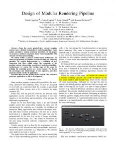
1.1 System Overview Our rendering pipeline is outlined in figure 1.1. First, all necessary initializations are performed on the CPU. These include loading information stored on disk (e.g., animation frames and polygonal meshes) and information generated as a preprocess (e.g., character positions) or in runtime (e.g., camera parameter updates). This information is used on the GPU to calculate the characters’ new positions, do view frustum culling, assign a specific level of detail (LOD) for each character and for level of detail sorting and character rendering. A brief description of each stage is given next: • Populating the Virtual Environment and Behavior. In these stages we specify the initial positions of all the characters, how they will move through the virtual environment and how they will interact with each other. The result is a set of updated character positions. • View Frustum Culling and Level of Detail Assignation. In this stage we use the characters’ positions to identify which characters will be culled. Additionally, we assign a proper LOD identifier to
1
i
i i
i
i
i
i
i
2
1. A Rendering Pipeline for Real-time Crowds
Figure 1.1. Rendering pipeline for crowd visualization. Dashed arrows correspond to data transferred from main memory to GPU memory only once at initialization.
the characters’ positions inside the view frustum according to their distance to the camera. • Level of Detail Sorting. The output of the View Frustum Culling and Level of Detail Assignation stage is a mixture of positions with different LODs. In this stage we sort each position according to its LOD identifier into appropriate buffers such that all the characters’ positions in a buffer have the same level of detail. • Animation and Draw Instanced. In this stage we will use each sorted buffer to draw the appropriate LOD character mesh using instancing. Instancing allows us to translate the characters across the virtual environment and add visual and geometrical variety to the individuals that conform the crowd. In the following sections we will present a detailed description of how we implemented these stages.
i
i i
i
i
i
i
i
1.2. Populating the Virtual Environment and Behavior
3
1.2 Populating the Virtual Environment and Behavior For simplicity, our virtual environment is a plane. It is parallel to the plane formed by the xz axes. The initial positions of the characters are calculated randomly and stored into a texture. For behavior, we implemented finite state machines (FSM) as fragment shaders. A finite state machine is used to update the characters’ positions following [Rudom´ın et al. 05, Mill´an et al. 06], in which a character will consult the value of a labeled world map and follow a very simple FSM that causes it to move right until it reaches the right edge of the map, at which point the agent changes state and starts moving left until it gets to the left edge. However, other GPU approaches such as [Erra et al. 09,Silva et al. 09] are ideal for this pipeline1 . Implemeting FSM as fragment shaders needs three kinds of textures: a world space texture, an agent texture and an FSM table texture. World space textures encode values for each location in the virtual environment. This would cover many types of maps: height maps, collision maps, interest area maps or action maps. We consider these maps as maps labeled with some value on each pixel. Agent textures have a pixel for each character and encode the state s of the character and its position (x, z) in the world map. Finally, the finite state machine is represented as a texture where given a certain state of the character and a certain input, we can obtain a new state and position of the character following the basic algorithm showed in listing 1.1. given agent i s t a t e=a g e n t [ i ] . s ; x=a g e n t [ i ] . x ; z=a g e n t [ i ] . z ; l a b e l=world [ x , z ] ; a g e n t [ i ] . s=fsm [ s t a t e , l a b e l ] ; a g e n t [ i ] . x += fsm [ s t a t e , l a b e l ] . d e l t a x ; a g e n t [ i ] . z += fsm [ s t a t e , l a b e l ] . d e l t a z ;
Listing 1.1. Basic algorithm to implement FSM as fragment shader.
1.3 View Frustum Culling View frustum culling (VFC) consists of eliminating groups of objects outside the camera’s view frustum. The common approach for VFC is to test the intersection between the objects and the six view frustum planes using their plane equations to determine the visibility of each object. In our 1 The
reason we recommend methods that use the GPU for behavior, in addition to the fact that these methods can simulate the behavior of tens of thousand characters efficiently, is that approaches using the GPU eliminate the overhead of transferring the new characters’ positions between the CPU and and the GPU on every frame.
i
i i
i
i
i
i
i
4
1. A Rendering Pipeline for Real-time Crowds
case, we implement a simpler method called radar VFC [Puig Placeres 05]. Radar VFC is based on the camera’s referential points. The method tests the objects for being in the view range or not, thus there is no need to calculate the six view frustum plane equations. On the other hand, objects tested against the view frustum are usually simplified using points or bounding volumes such as bounding boxes (oriented or axis-aligned) or spheres. In our case, we use points (the characters’ positions) together with radar VFC to perform only three tests to determine the character’s visibility. In addition, to avoid the culling of characters that are partially inside the view frustum, we increase the view frustum size by ∆ units2 (figure 1.2).
Figure 1.2. View frustum culling.
As mentioned earlier, radar VFC is based on camera referential points. In other words, the camera has a referential based on the three unit vectors x, y and z as shown in figure 1.3, where c is the position of the camera, n is the center of the near plane and f is the center of the far plane.
Figure 1.3. Camera’s referential based on the three unit vectors x, y, z.
The idea behind radar VFC is that once we have the character’s position 2 The
value of ∆ is obtained by visually adjusting the view frustum.
i
i i
i
i
i
i
i
1.3. View Frustum Culling
5
p to be tested against the view frustum, we find the coordinates of p in the referential and then use this information to find out if the point is inside or outside the view frustum. The first step is to find the camera’s referential. Let d be the camera’s view direction, u the camera’s up vector, then unit vectors X, Y, Z that conform the referential are calculated using equations 1.1, 1.2 and 1.3. Z = ∥d∥ =
√ d2x + d2y + d2z
(1.1)
X = ∥Z ⊗ u∥
(1.2)
Y = ∥X ⊗ Z∥
(1.3)
Once we have calculated the referential, the next step is to compute the vector v that goes from the camera center c to the agent’s position p using equation 1.4: v =p−c
(1.4)
Next, the vector v is projected onto the camera referential, i.e., onto X, Y, Z unit vectors. Radar VFC first tests vector v against the Z unit vector; v is outside the view frustum if its projection projZ v ∈ / (N earplane , F arplane ). Notice that the projection of a vector a into a unit vector B is given by the dot product of both vectors, i.e. projB a = a · B. If projZ v ∈ [N earplane , F arplane ], then vector v is tested against the Y unit vector; v will be outside the view frustum if its projection projY v ∈ / (−(h/2 + ∆), h/2 + ∆) interval. Where h is the height of the view frustum at v ′ s position and ∆ is the value used to increase the view frustum size as shown in figure 1.2. The height h is calculated using equation 1.5: h = projZ v × 2 × tan
f ov : f ov ∈ [0, 2π] 2
(1.5)
where f ov is the field of view angle. If projY v ∈ (−(h/2 + ∆), h/2 + ∆), then vector v is tested against X unit vector, i.e. v is outside the view frustum if its projection projX v ∈ / (−(w/2 + ∆), w/2 + ∆) interval, where w is the width of the view frustum, given in equation 1.6: w = h × ratio
(1.6)
where ratio is the aspect ratio value of the view frustum.
i
i i
i
i
i
i
i
6
1. A Rendering Pipeline for Real-time Crowds
VFC and LOD assignation stages are performed using a geometry shader. This shader receives as input the agent texture that was updated in behavior stage (section 1.2), and it will emit the positions (x, z) which are inside the view frustum and a LODid . The resultant triplets (x, y, LODid ) are stored in a vertex buffer object using the OpenGL transform feedback feature. Listing 1.2 shows the code that performs radar VFC in GLSL. [ v e r t e x program ] void main ( void ) { gl TexCoord [ 0 ] = g l M u l t i t e x C o o r d 0 ; gl Position = gl Vertex ; } [ geometry program ] #define INSIDE t r u e #define OUTSIDE f a l s e u n i f o r m sampler2DRect p o s i t i o n ; u n i f o r m f l o a t n e a r P l a n e , f a r P l a n e , tang , r a t i o , d e l t a ; u n i f o r m v e c 3 camPos , X, Y, Z ; bool pointInFrustum ( vec3 point ) { // c a l c u l a t i n g v = p − c v e c 3 v = p o i n t − camPos ; // c a l c u l a t i n g t h e p r o j e c t i o n o f v i n t o Z u n i t v e c t o r f l o a t pcz = dot ( v , Z ) ;
// F i r s t t e s t : t e s t a g a i n s t Z u n i t v e c t o r i f ( pcz > f a r P l a n e | | pcz < n e a r P l a n e ) return OUTSIDE ; // c a l c u l a t i n g t h e p r o j e c t i o n o f v i n t o Y u n i t v e c t o r f l o a t pcy = dot ( v ,Y ) ; f l o a t h = pcz ∗ tang ; h = h + delta ; // Second t e s t : t e s t a g a i n s t Y u n i t v e c t o r i f ( pcy > h | | pcy < −h ) return OUTSIDE ; // c a l c u l a t i n g t h e p r o j e c t i o n o f v i n t o X u n i t v e c t o r f l o a t pcx = dot ( v ,X ) ; float w = h ∗ ratio ; w = w + delta ; // Third t e s t : t e s t a g a i n s t X u n i t v e c t o r i f ( pcx > w | | pcx < − w ) return OUTSIDE ; return INSIDE ; }
i
i i
i
i
i
i
i
1.3. View Frustum Culling
7
void main ( void ) { v e c 4 pos = t e x t u r e 2 D R e c t ( p o s i t i o n , g l T e x C o o r d I n [ 0 ] [ 0 ] . s t ) ; i f ( p o i n t I n F r u s t u m ( pos . xyz ) ) { g l P o s i t i o n = pos ; EmitVertex ( ) ; EndPrimitive ( ) ; } }
Listing 1.2. Code for radar view frustum culling in GLSL.
1.3.1 Assigning Level of Detail After determining which positions are inside the view frustum, the next step is to assign a LODid according to a given metric. In this case, we use discrete LOD3 which consists of creating different LODs for each character as a preprocess. At run-time, the appropriate character’s LOD is rendered using its LODid . Metrics for assigning values to LODid can be based on distance to the camera, model size in screen space, eccentricity of the model with respect to the camera or perceptual factors among others. For performance and simplicity, we are using the distance to the camera as our metric; we also use visual perception to reduce the popping effect. The idea behind the distance to the camera metric is to select (or in our case, assign) the appropriate LOD based on the distance between the model and the viewpoint (i.e., coarser resolution for distant geometry). Nevertheless, instead of computing the Euclidean distance between the object and the viewpoint, we define the appropriate LOD as a function of the view range and the far plane. These values are obtained by the camera referential points. The camera’s view range is given by unit vector Z and it is limited by the distance between the camera center, c, and the F arplane value. Thus, we test the projection of v onto Z, projZ v, against different fixed intervals of the view range to assign a value to LODid . A common approach for manually assigning values to LODid is using if statements as shown in listing 1.3. Nevertheless, we can reduce GPU branching by eliminating the if statements and by using a sum of unit step functions instead (equation 1.7): 3 It
has been shown in [Mill´ an et al. 06] that 2D representations such as impostors make it possible to render tens of thousands of similar animated characters, but 2D representation approaches need manual tunning and generate huge amount of data if several animation sequences are present and/or geometrical variety is considered.
i
i i
i
i
i
i
i
8
1. A Rendering Pipeline for Real-time Crowds
... i f p r o j Z v r a n g e 0 & p r o j Z v r a n g e 1 & p r o j Z v