Pipeline Rendering: Interaction and Realism. Through Hardware-Based Multi-Pass Rendering. Paul Joseph Diefenbach. University of Pennsylvania. Follow this ...
PIPELINE RENDERING: INTERACTION AND REALISM THROUGH HARDWARE-BASED MULTI-PASS RENDERING PAUL JOSEPH DIEFENBACH A DISSERTATION in
COMPUTER AND INFORMATION SCIENCE Presented to the Faculties of the University of Pennsylvania in Partial Ful llment of the Requirements for the Degree of Doctor of Philosophy. 1996
Norman I. Badler Supervisor of Dissertation
Peter Buneman Graduate Group Chairperson
c Copyright 1996 by Paul Joseph Diefenbach
ii
Acknowledgments Lazlo's Chinese Relativity Axiom: No matter how great your triumphs or how tragic your defeats, approximately one billion Chinese couldn't care less.
There are many people who contributed to this thesis both in direct support as well as through personal support, and I am greatly indebted to them all. Foremost, I would like to thank my advisor, Dr. Norman Badler, whose con dence started me along the doctoral path, whose support enabled my research, and whose expectations helped push the nal result. I am sincerely thankful to my other committee members, namely Dimitri Metaxas, Insup Lee, Julie Dorsey, and Greg Ward, who provided valuable direction in turning a disjoint proposal into a cohesive, directed thesis. I am particularly indebted to Greg Ward, whose expertise and guidance helped strengthen the rendering aspects of this work, and whose bathroom model and images provided an invaluable testbed. I am also immensely thankful for the support, friendship, and help of the students and sta� of the Center for Human Modeling and Simulation. They have always been willing to readily share their knowledge and expertise (as well as their machines) when needed. In particular, I am grateful to Je� Nimero� for his help with rendering jargon and his bibtex-like knowledge, to Doug DeCarlo for his help with SGI architectural quirks and for our discussions on shadow volumes, and to John Granieri for providing the impetus for the specular image work. I would also like to thank Min-Zhi Shao for his help with his radiosity program to garner the indirect solution. Additionally, I am appreciative to those people outside the university who provided assistance with my research and implementation. This includes Jim Arvo, who iii
was most generous in providing his images and the intricate butter�y environments, and Paul Heckbert who provided additional shadowing references. On a personal note, I am extremely lucky to have many friends and family which provided innumerous support through these many years, and managed to keep me (mostly) sane throughout. To my best friend, Dr. Jana Kosecka, who began and ended (3 days early) this endeavor with me, you have been my \dub strom" as well, and I will miss you more than you know. Without you, I would never have nished. I am also fortunate to have had a couple of other friends at Penn which have also gone beyond what anyone could hope for in always looking out for me and who have meant so much to me. This includes former lab member Leanne Hwang, one of the sweetest people I know, and who, with Min, kept me fed despite giving me grey hairs� and includes Diane Chi who literally went out of her way to be a tremendous friend and who, with Rox, proved to be always full of \surprises". I am also grateful for my continuing friendship with Kasturi Bagchi, Esq., who su�ered through my paper deadlines and was my personal \advocate", inspiration, and escape throughout this work. To my longtime friends including Robert, Andy, Gary, Glenn and Auts, Sarah, Jui and Jim, May, Susanne, and Steve, I am very thankful for the all-too-infrequent times we were able to get together during this work. There are many other friends not mentioned but who are never far from my mind. Lastly, but most importantly, I am fortunate to have been raised in a loving and supportive family, which provided the foundation for everything I have achieved. I have no means to truly thank my mom, Natalie, who is the mother every child would wish for and whose unconditional love and support has always been the one constant throughout my life. I dedicate this thesis to you. I thank my dad, Joseph, for instilling in me a sense of independence and hard work, and for pushing me to do my best. I also am grateful to have my Grandma Marie, my sister Terri and brother-in-law Rob, and my amazing nephew Evan, all in my life. They, along with my other relatives, always make coming home truly \home". iv
Abstract
While large investments are made in sophisticated graphics hardware, most realistic rendering is still performed o�-line using ray trace or radiosity systems. A coordinated use of hardware-provided bitplanes and rendering pipelines can, however, approximate ray trace quality illumination e�ects in a user-interactive environment, as well as provide the tools necessary for a user to declutter such a complex scene. A variety of common ray trace and radiosity illumination e�ects are presented using multi-pass rendering in a pipeline architecture. We provide recursive re�ections through the use of secondary viewpoints, and present a method for using a homogeneous 2-D projective image mapping to extend this method for refractive transparent surfaces. This paper then introduces the Dual Z-bu�er, or DZ-bu�er, an evolutionary hardware extension which, along with current framebu�er functions such as stencil planes and accumulation bu�ers, provides the hardware platform to render non-refractive transparent surfaces in a back-to-front or front-to-back order. We extend the traditional use of shadow volumes to provide re�ected and refracted shadows as well as specular light reclassi�cation. The shadow and lighting e�ects are then incorporated into our recursive viewpoint paradigm. Global direct illumination is provided through a shadow blending technique. Hardware surface illumination is �t to a physically-based BRDF to provide a better local direct model, and the framework permits incorporation of a radiosity solution for indirect illumination as well. Additionally, we incorporate material properties including translucency, light scattering, and non-uniform transmittance to provide a general framework for creating realistic renderings. The DZ-bu�er also provides decluttering facilities such as transparency and clipping. This permits selective scene viewing through arbitrary view-dependent and non-planar clipping and trnasparency surfaces in real-time. The combination of these techniques provide for understandable, realistic scene rendering at typical rates 5-50 times that of a comperable ray trace images. In addition, the pixel-parallel nature of these methods leads to exploration of further hardware rendering engine extensions which can exploit this coherence.
v
Contents Acknowledgments
iii
Abstract
v
1 Introduction and Motivation
1
1.1 Problems with interactive rendering : : : : : : : : : : : : : : : : : : : 3 1.2 Our Approach : : : : : : : : : : : : : : : : : : : : : : : : : : : : : : : 6 1.3 Overview : : : : : : : : : : : : : : : : : : : : : : : : : : : : : : : : : : 10
2 Background
2.1 Rendering Methods : : : : : : : : : 2.1.1 Basic Recursive Ray Tracing 2.1.2 Backward Ray Tracing : : : 2.1.3 Radiosity : : : : : : : : : : 2.1.4 Two-Pass Methods : : : : : 2.1.5 Beam Tracing : : : : : : : : 2.1.6 Hardware-based Rendering : 2.2 De nitions : : : : : : : : : : : : : : 2.2.1 Stencil Planes : : : : : : : : 2.2.2 Accumulation Bu�er : : : : 2.2.3 Alpha Blending : : : : : : : 2.2.4 Shadow Volumes : : : : : : vi
: : : : : : : : : : : :
: : : : : : : : : : : :
: : : : : : : : : : : :
: : : : : : : : : : : :
: : : : : : : : : : : :
: : : : : : : : : : : :
: : : : : : : : : : : :
: : : : : : : : : : : :
: : : : : : : : : : : :
: : : : : : : : : : : :
: : : : : : : : : : : :
: : : : : : : : : : : :
: : : : : : : : : : : :
: : : : : : : : : : : :
: : : : : : : : : : : :
: : : : : : : : : : : :
: : : : : : : : : : : :
: : : : : : : : : : : :
: : : : : : : : : : : :
12 12 12 14 16 17 17 19 21 21 22 23 23
2.2.5 Light Volumes : : : : : : : : : : : : : : : : : : : : : : : : : : : 24 2.2.6 In-Out Refractions : : : : : : : : : : : : : : : : : : : : : : : : 24
3 Specular Surface Rendering
3.1 Re�ections : : : : : : : : : : : : : : 3.2 Refractive Transparency : : : : : : 3.3 Non-Refractive Transparency : : : 3.3.1 De nitions : : : : : : : : : : 3.3.2 Back-to-Front Transparency 3.3.3 Front-to-Back Transparency 3.4 Translucency : : : : : : : : : : : :
4 Shadow and Light Volumes
: : : : : : :
: : : : : : :
4.1 Shadow Volumes : : : : : : : : : : : : 4.1.1 Silhouette Volume : : : : : : : 4.1.2 View in Volume : : : : : : : : : 4.2 Specular Shadows : : : : : : : : : : : : 4.2.1 Intersection Recursion : : : : : 4.2.2 Virtual Position Recursion : : : 4.3 Light Volumes : : : : : : : : : : : : : : 4.3.1 Single-Bounce Light Volumes : 4.3.2 Multiple-Bounce Light Volumes 4.4 Light Accumulation : : : : : : : : : : : 4.4.1 Attenuation : : : : : : : : : : : 4.4.2 Filtering : : : : : : : : : : : : :
5 Multi-pass Process
: : : : : : : : : : : : : : : : : : :
: : : : : : : : : : : : : : : : : : :
: : : : : : : : : : : : : : : : : : :
: : : : : : : : : : : : : : : : : : :
: : : : : : : : : : : : : : : : : : :
: : : : : : : : : : : : : : : : : : :
: : : : : : : : : : : : : : : : : : :
: : : : : : : : : : : : : : : : : : :
: : : : : : : : : : : : : : : : : : :
: : : : : : : : : : : : : : : : : : :
: : : : : : : : : : : : : : : : : : :
: : : : : : : : : : : : : : : : : : :
: : : : : : : : : : : : : : : : : : :
: : : : : : : : : : : : : : : : : : :
: : : : : : : : : : : : : : : : : : :
: : : : : : : : : : : : : : : : : : :
: : : : : : : : : : : : : : : : : : :
25 25 28 34 36 37 42 46
52 52 54 55 57 58 60 66 66 67 69 72 73
78
5.1 Recursion : : : : : : : : : : : : : : : : : : : : : : : : : : : : : : : : : 78 5.2 Stenciling : : : : : : : : : : : : : : : : : : : : : : : : : : : : : : : : : 79 vii
6 Illumination Model
6.1 Global Direct Illumination : 6.1.1 Light Accumulation : 6.1.2 Soft Shadows : : : : 6.2 Local Direct Illumination : : 6.3 Indirect Illumination : : : : 6.4 Total Scene Illumination : :
7 Performance 7.1 7.2 7.3 7.4
Di�use Transport Shadows : : : : : Specular Images : Scene Dynamics :
8 Scene Uncluttering
: : : :
: : : :
: : : :
8.1 Background : : : : : : 8.1.1 Clipping Planes 8.1.2 CSG : : : : : : 8.2 Clipping Surface : : : 8.3 Transparency Surface : 8.4 Software Emulation : :
: : : : : : : : : :
: : : : : : : : : :
: : : : : : : : : :
: : : : : : : : : : : : : : : :
: : : : : : : : : : : : : : : :
: : : : : : : : : : : : : : : :
9 Extensions
: : : : : : : : : : : : : : : :
: : : : : : : : : : : : : : : :
: : : : : : : : : : : : : : : :
: : : : : : : : : : : : : : : :
: : : : : : : : : : : : : : : :
: : : : : : : : : : : : : : : :
9.1 Limitations : : : : : : : : : : : : : : : : : : 9.2 Hardware Extensions : : : : : : : : : : : : : 9.3 Hardware Platforms : : : : : : : : : : : : : 9.3.1 Object-Order Rasterization Systems : 9.3.2 Image-Order Rasterization Systems : 9.3.3 Hybrid Systems : : : : : : : : : : : : viii
: : : : : : : : : : : : : : : : : : : : : :
: : : : : : : : : : : : : : : : : : : : : :
: : : : : : : : : : : : : : : : : : : : : :
: : : : : : : : : : : : : : : : : : : : : :
: : : : : : : : : : : : : : : : : : : : : :
: : : : : : : : : : : : : : : : : : : : : :
: : : : : : : : : : : : : : : : : : : : : :
: : : : : : : : : : : : : : : : : : : : : :
: : : : : : : : : : : : : : : : : : : : : :
: : : : : : : : : : : : : : : : : : : : : :
: : : : : : : : : : : : : : : : : : : : : :
: : : : : : : : : : : : : : : : : : : : : :
: : : : : : : : : : : : : : : : : : : : : :
: : : : : : : : : : : : : : : : : : : : : :
84 85 86 87 90 101 102
106 111 111 113 115
117 117 118 118 119 120 120
123 123 124 125 126 129 130
10 Conclusion
132
A Projective Maps
137
B Refraction Approximation
139
10.1 Contributions : : : : : : : : : : : : : : : : : : : : : : : : : : : : : : : 132 10.2 Future Work : : : : : : : : : : : : : : : : : : : : : : : : : : : : : : : : 134 10.3 Conclusion : : : : : : : : : : : : : : : : : : : : : : : : : : : : : : : : : 135
ix
List of Tables 7.1 7.2 7.3 7.4
Frame rendering statistics for bathroom environment. : : : : : : : : : 109 Single image/single light rendering statistics for bathroom environment.110 Varying Shadow Settings : : : : : : : : : : : : : : : : : : : : : : : : : 113 Varying Specular Settings : : : : : : : : : : : : : : : : : : : : : : : : 115
x
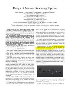
List of Figures 1.1 Multi-pass Pipeline Rendering Process : : : : : : : : : : : : : : : : : 1.2 Multi-pass Pipeline Rendering Image : : : : : : : : : : : : : : : : : :
8 9
2.1 2.2 2.3 2.4 2.5
Ray Trace Rays : : : : : : : : : : : : : : : : Caustic Polygons from Light Beam Tracing : Virtual viewpoint for re�ected beam : : : : Z -bu�er based rendering pipeline : : : : : : Shadow volumes : : : : : : : : : : : : : : : :
: : : : :
: : : : :
: : : : :
: : : : :
: : : : :
: : : : :
: : : : :
: : : : :
: : : : :
: : : : :
: : : : :
: : : : :
: : : : :
: : : : :
13 16 19 19 20
3.1 3.2 3.3 3.4 3.5 3.6 3.7 3.8 3.9 3.10 3.11 3.12
Recursive Re�ection : : : : : : : : : Refracted Image vs. Camera Image : Undistorted and Distorted Refraction Tangent Law for paraxial rays : : : : Uncorrected Refraction : : : : : : : : Corrected Refraction : : : : : : : : : Back-to-front rendered area : : : : : Back-to-front iterations : : : : : : : : Front-to-back iterations : : : : : : : : Partial Specular Image : : : : : : : : Frosted Glass : : : : : : : : : : : : : Glossy Table : : : : : : : : : : : : : :
: : : : : : : : : : : :
: : : : : : : : : : : :
: : : : : : : : : : : :
: : : : : : : : : : : :
: : : : : : : : : : : :
: : : : : : : : : : : :
: : : : : : : : : : : :
: : : : : : : : : : : :
: : : : : : : : : : : :
: : : : : : : : : : : :
: : : : : : : : : : : :
: : : : : : : : : : : :
: : : : : : : : : : : :
: : : : : : : : : : : :
27 29 30 32 32 33 38 41 43 46 49 50
: : : : : : : : : : : :
: : : : : : : : : : : :
: : : : : : : : : : : :
: : : : : : : : : : : :
4.1 Shadow volume clipped by front clipping plane. : : : : : : : : : : : : 55 xi
4.2 4.3 4.4 4.5 4.6 4.7 4.8 4.9 4.10 4.11 4.12
Light interaction with refractive surface : : : : : Refracted Caustics and Shadows : : : : : : : : : Re�ected light and shadows : : : : : : : : : : : Shadow volumes generated involving R1. : : : : Light volume clipped by both refracting planes. Light volume clipped by both re�ecting planes. VPR Light Volumes. : : : : : : : : : : : : : : : VPR Lighting and Shadows. : : : : : : : : : : : Light and view coordinate systems. : : : : : : : Projected Textures : : : : : : : : : : : : : : : : Projected Texture Light Pattern : : : : : : : : :
: : : : : : : : : : :
: : : : : : : : : : :
: : : : : : : : : : :
: : : : : : : : : : :
: : : : : : : : : : :
: : : : : : : : : : :
: : : : : : : : : : :
: : : : : : : : : : :
: : : : : : : : : : :
: : : : : : : : : : :
: : : : : : : : : : :
: : : : : : : : : : :
58 59 60 63 68 69 70 71 75 76 77
5.1 Recursive Image Rendering : : : : : : : : : : : : : : : : : : : : : : : : 80 5.2 Recursive Stenciling : : : : : : : : : : : : : : : : : : : : : : : : : : : : 81 6.1 6.2 6.3 6.4 6.5 6.6 6.7 6.8 6.9 6.10 6.11 6.12 6.13 6.14
Jittered Light Shadow Volumes : : : : : : : : : Jitter Approximation Shadow Volumes : : : : : BRDF Scattering Angles : : : : : : : : : : : : : Phong BRDF Notation : : : : : : : : : : : : : : Specular Scattering Components (�i = �=6) : : Gaussian vs. Phong Specular Term : : : : : : : Simpli ed Gaussian vs. Fit Phong : : : : : : : : Full Gaussian vs. Fit Phong : : : : : : : : : : : Partial Gaussian vs. Fit Phong : : : : : : : : : Full Gaussian vs. Phong vs. Fit Phong (view 1) Full Gaussian vs. Phong vs. Fit Phong (view 2) Gaussian vs. Phong Specular Highlights : : : : Calculating Indirect Illumination Image : : : : : Gaussian vs. Phong Scene Illumination : : : : : xii
: : : : : : : : : : : : : :
: : : : : : : : : : : : : :
: : : : : : : : : : : : : :
: : : : : : : : : : : : : :
: : : : : : : : : : : : : :
: : : : : : : : : : : : : :
: : : : : : : : : : : : : :
: : : : : : : : : : : : : :
: : : : : : : : : : : : : :
: : : : : : : : : : : : : :
: : : : : : : : : : : : : :
: : : : : : : : : : : : : :
89 89 91 92 93 94 95 96 97 98 99 100 103 105
7.1 7.2 7.3 7.4 7.5
Rendering Relationship : : : : : : : : : Pipeline Rendering Relationship : : : : Varying Shadow Settings : : : : : : : : Varying Specular Settings : : : : : : : Varying Scene Geometry and Lighting
: : : : :
: : : : :
: : : : :
: : : : :
: : : : :
: : : : :
: : : : :
: : : : :
: : : : :
: : : : :
: : : : :
: : : : :
: : : : :
: : : : :
: : : : :
: : : : :
: : : : :
107 108 112 114 116
8.1 Clipping/Transparency Surface : : : : : : : : : : : : : : : : : : : : : 121
xiii
Chapter 1 Introduction and Motivation \Ok, wait a moment here. Hold on. There. Now you see the change was made in real time." Frame showperson at Seybold conference As the power of today's graphics workstations has increased, so too have the demands of the user. Whereas realism and interaction were previously mutually exclusive, today's graphic workstations are providing the platform to develop applications with photo-realistic, interactive, dynamic, comprehensible environments. Unfortunately, today's applications generally do not permit or take advantage of all of these features. Traditional interactive computer graphics developed from the early military applications such project SAGE in the late 1950s. SAGE, for Semi-Automatic Ground Environment system, provided a CRT radar-like display of potential Soviet bomber targets and interceptors with a light-pen interface for assigning interceptors to targets. Symbols and identi ers replaced radar blips as the graphical representation. CAD applications also began to develop around this time with systems such as APT (Automatically Programmed Tooling) allowing speci cation of part geometry and milling paths. Speci cation of this, however, was performed entirely o�-line. In 1963, one of the rst presentations of interactive graphics on a CRT system was made by Sutherland at the Joint Computer Conference �Sut63]. His Sketchpad 1
system enabled interactive creation and manipulation of parts using display primitives such as lines, arcs, etc. This system introduced the notion of hierarchies based on a set of graphic primitives. It also introduced many interaction techniques using the keyboard and lightpen. This system provided the foundation of modern graphics packages and libraries such as PHIGS�Hew84] and SGI's GL�SGI90]. The need for computer-generated imagery for �ight simulators led to the development of raster graphics systems. Raster graphics were introduced in the early 1970s with systems such as the Alto from Xerox PARC. This permitted lled, colored, solid surfaces which had been essentially unachievable on vector displays. This system provided the foundation for the modern realistic images which are common in today's interactive applications. Hidden surface removal in these raster systems led to a variety of sorting algorithms �NNS72]�War69]�Sch69b], and eventually let to the development of the Z bu�er �Cat74] which resolved visibility con�icts at the pixel level. Some of these early hidden-surface removal methods�App68]�GN71] also introduced the notion of ray casting�Rot82], which later formed the bases of modern photo-realistic rendering techniques. Whitted �Whi80] introduced ray tracing as a means to integrate re�ection, refraction, hidden surface removal, and shadows into a single model. This paradigm provided the means to build photo-realistic images one pixel at a time by casting rays from an eye-point through the pixel into the environment and tracing its path. As this method operates on a pixel-by-pixel basis, it is inherently non-interactive. Ray tracing techniques continued to expand in the 1980s and 1990s to include variations such as backward ray tracing and distribution ray tracing, as increasingly accurate physical properties such as caustics and shadow refraction were desired. Other methods were developed to produce photo-realistic images, the most notable being radiosity introduced to computer graphics by Goral et al. �GTGB84]. This method relies on energy exchange between surfaces in the environment, a calculation which also makes this method non-interactive. This calculation is performed 2
as a pre-computation on a static environment. Interactive view changes are possible in this environment, however the necessity of a static environment precludes any real user manipulation of the environment. Hardware-based graphics continued to evolve, permitting sophisticated real-time features such as texture mapping, re�ection mapping, transparency, and shadows. While many of these features are implemented as visual approximations instead of the physics-based ray tracing and radiosity solutions, they do provide realistic looking images at interactive rates. The current state of computer graphics has in essence diverged into two areas: one based on o�-line calculations to produce non-interactive, physically-based, photo-realistic images� the other based on hardware-implemented calculations to produce real-time, physically-approximated, pseudo-realistic images. Each of these approaches has its advantages and shortcomings.
1.1 Problems with interactive rendering Much attention has been devoted to photo-realistic rendering techniques as ray tracing and radiosity packages have become increasingly sophisticated. These methods provide a basic foundation of visual cues and e�ects to produce extremely high quality and highly accurate images at a considerate cost, namely, computation time. Neither of these techniques have any widespread application in true interactive and dynamic environments, such as animation creation and virtual worlds. Hardware-based 3-D graphics systems provide pseudo-realistic images at interactive rates through use of minute geometric detailing and other visual cues. Sophisticated graphics pipelines permit real-time texturing and shadows, in addition to a variety of basic lighting e�ects. These systems do not provide the sophisticated lighting e�ects and material properties that the photo-realistic systems do. In order to clarify the limitations of the above described rendering approaches, each is individually addressed. 3
Ray Tracing Systems based on forward ray tracing �Gla89] are non-interactive and su�er from problems inherent in the technique �WW92] such as costly intersection testing and incorrect specular illumination. In addition, only a few attempt to accurately handle indirect illumination �Kaj86]. Backward ray tracing systems �Arv86]�HH84]�CF87] more accurately handle caustics� but again these methods are very time-intensive and not remotely interactive. Even the fastest ray tracing systems require static geometry to achieve their results �SS89b].
Radiosity Many so-called interactive environments such as Virtual Building systems �ARB90] �TS91] rely on precomputation of static environments to form progressive radiosity solutions. Other systems dealing with lighting e�ects �Dor93] rely on a series of images from a single viewpoint. All of the systems su�er from large computational overhead and unchangeable geometry. Even in incremental radiosity solutions �Che90], geometry changes require signi cant recomputation time. In addition, radiosity-based solutions inhibit the use of re�ective and refractive surfaces. Ray trace/radiosity multi-pass or combined systems �WCG87]�PSV90] enable this specularity, but only image-based systems �CW93]�NDR95] permit any level of dynamic interaction although they sacri ce image resolution.
Geometric detail In systems which provide realism through minute geometric detailing, this vast amount of data itself presents several problems. Whereas previous applications used graphics to simulate individual parts of a complex environment, current applications focus on visualization of the entire system together at maximal resolution. Where a small CAD part or a single room used to be the level of detail supported, current architectures and techniques now permit visualization of an entire airplane or 4
building at the same resolution of detail. Interactive rates have been maintained in systems such as walk-through packages by using complex view dependencies to limit the amount of data needed at any particular view, e.g. �TS91]. Cohesive CAD, analysis, and visualization tools used in Simulation Based Design systems also require this data management, in addition to sophisticated means of presentation and user selection of desired features. While these systems may be able to manage and present these vast amounts of visual data, visual overload will result if the user is not able to disregard unwanted sections. Many techniques currently exist to minimize or de-clutter unwanted visual information. Two of the most frequently used are clipping surfaces and transparency. Unfortunately, today's hardware-based graphic systems do not handle either of these in a wholly satisfactory manner. While the use of arbitrarily oriented clipping planes is common in many graphics systems, their use is limited to planar visual cuts. This presents a broad elimination of visual data, whereas a ne directed or sculptured cut is often desired such as in medical image reconstruction and visualization. Transparency is also available through the use of alpha blending, however the actual rendering is often incorrect: correct transparency requires depth-ordered drawing of the surfaces, which does not comply with the Z -bu�er based sorting procedure used in almost all graphics systems. In addition, with the increased reliance on hardware texture mapping to add visual complexity, semi-transparent textures will further stress the need for a correct hardware-based rendering of non-opaque surfaces.
Graphics pipeline rendering Advanced hardware architectures such as the SGI Reality EngineTM have brought an added level of realism and interaction to dynamic environments through the use of sophisticated graphics pipelines and added levels of screen bu�er information. These features have enabled software developers to bring previously unavailable details such as shadows and mirrors to many interactive applications, as well as allow 5
the user to selectively see desired details by clipping away unwanted portions. These and other hardware provisions have yet to be fully exploited, though clever programming techniques by several implementors have produced real-time shadows and mirrors�Hei91]�KSC81].
1.2 Our Approach Our research expands hardware-based pipeline rendering techniques to present a platform which does provide realism and user interaction, as well as additional means in which to manipulate and comprehend these complex scenes. It proposes evolutionary, not revolutionary, modi cations of the graphics pipeline where necessary, and the techniques to use these features for the aforementioned purposes. Although slight hardware modi cations may be introduced, many such modi cations are based on similar features found in other architectures. This thesis is an introduction of new techniques using these features� it is not an introduction of a new rendering architecture itself. With the high investment in pipeline rendering architectures, better rendering and interactive techniques using these architectures becomes a necessity as the demands of the applications grow. Our approach to rendering is to take full advantage of the provided graphics rendering pipeline to provide realistic rendering in a dynamic environment. Much of this work is focused on using multi-pass rendering techniques based on existing pipeline architectures. Through these multi-pass methods, we provide a means to include not only re�ection but a technique for approximating refractive planar surfaces as well. The model presented extends the current re�ection techniques to provide an arbitrary level of refraction and re�ection based on bit-plane depth for use in \hall-of-mirror" type environments and to provide a close approximation for refractive objects. An image transform is presented to correct for perspective distortions during the image mapping of the secondary refracted image. For non-refractive transparent surfaces, a display architecture modi cation is proposed to provide the facilities for correct 6
sorted surface blending. This extension, the Dual Z -bu�er or DZ -bu�er, along with current frame-bu�er functions such as stencil planes and accumulation bu�ers, provide the hardware platform to render correct transparent surfaces through multiple rendering passes. Multiple rendering passes also provide the bases for shadow volume support with specular surfaces. We provide a practical shadow volume method which is extended for interaction with specular light reclassi cation. This multi-pass method is combined with the similar specular surface stenciling methods to provide a recursive methodology which not only preserves shadows in all re�ected and refracted images, but which also accounts for refraction and re�ection of the light and shadows in the primary and secondary images as well. Our pipeline rendering platform also includes utilizing hardware provided features such as fog and texture mapping to provide simulation of varying material properties such as translucency and ltering. Fitting of the hardware lighting model and surface attributes to a more physics-based and empirically-derived model further provides more realistic rendering. Combined with the multi-pass features, these techniques provide an alternative to ray tracing for creating fast, approximate specular lighting e�ects at rates on the order of 5-50 times faster as documented in the examples. We additionally support incorporation of di�use illumination e�ects, presenting full scene illumination for dynamic environments. The coordination of these processes is seen in Figure 1.1, with e�ects demonstrated in Figure 1.2. Finally, we introduce scene de-cluttering facilities to promote user comprehension of these interactive environments. This includes selective visualization of the environment by supporting arbitrary clipping surfaces in real-time. By combining this with our sorted transparency procedure, the arbitrary clipping surface can be used as an arbitrary transparency surface, making all enclosed areas transparent. 7
Draw Environment More Specs?
N
Draw Image Draw Image
Y
Draw w/ Indirect (Ch. 6.3)
Reclassify View (Ch. 3.1,3.2)
Draw Transparent Objects (Ch. 3.3)
Draw w/ Ambient (Ch. 6.1.1)
Draw Environment
Make Shadows Make Shadows
More Specs?
N
Draw Shadows Draw Shadows
Y Reclassify Light (Ch. 4.3)
Make Shadow Volumes (Ch. 4.1,4.2)
Make Shadows
Draw w/ Direct Illum. (Ch. 6.1,6.2)
Figure 1.1: Multi-pass Pipeline Rendering Process
8
Figure 1.2: Multi-pass Pipeline Rendering Image
9
1.3 Overview Chapter 2 rst introduces the sophisticated illumination e�ects which traditionally appear only in photo-realistic rendering methods. This includes discussion of the bene ts and limitations of each method. Current hardware-based methods used to achieve these e�ects are then presented. The next three chapters discuss the primary multi-pass contributions for pipeline rendering of specular environments. Chapter 3 discusses specular surface rendering. It rst introduces the standard method of implementing re�ection through secondary viewpoints. The case of refractive transparency is then investigated, using an extension of the re�ection method for refractions. Non-refractive transparency is additionally supported through techniques which provide correct transparency blending. This includes introducing some required pipeline extensions and support functions, including a Dual Z -bu�er. Both back-to-front and front-to-back traversal methods are included. Simulation of scattering material properties such as translucency are also included. Chapter 4 describes our implementation of shadows which work in conjunction with the re�ections and refractions. This includes discussion of a practical implementation of shadow volumes, as well as the various methods of modeling their interaction with specular surfaces. The current implementation's use of virtual light sources (or light source reclassi cation) is discussed in a recursive framework, with this method eventually extended to creation of specular light volumes. Material transmission and re�ection properties for these light volumes are then described, including simulation of non-uniform surfaces. Chapter 5 brings the two previous chapters together as a composite recursive procedure. Coordinated recursion of the two multi-pass methods is rst detailed, followed by allocation speci cs of the primary shared resource, the stencil bu�er. As the previous chapters introduce the primary shadowing techniques, Chapter 6 10
discusses use of these techniques in producing physically-based global and local illumination e�ects. This includes global direct e�ects such as light accumulation and area light sources, local direct e�ects through tting of the hardware lighting model, and indirect e�ects through incorporating a radiosity-generated di�use-di�use transfer solution. Both direct and indirect e�ects are then evaluated in toto. The performance of all of the previously introduced features are examined in Chapter 7. This focuses on the use of pipeline rendering to bridge the quality/ performance gap of traditional rendering. Quality versus timing tradeo�s are discussed in the context of both user-selected criteria and automatic selection in progressive re nement applications. Whereas the previous chapters focus on the realism of dynamic scenes, Chapter 8 focuses on user comprehension and interaction with these environments. The use of clipping and transparency surfaces is discussed for selective scene rendering. The DZ -bu�er is used to provide arbitrary clipping surfaces� this is combined with the non-refractive transparency method for providing arbitrary transparency surfaces which, analogous to clipping surfaces, render all enclosed surfaces and volumes transparent. Chapter 9 addresses the limitations of the system, particularly in regards to the current hardware platform as well as possible extensions to the platform. Other graphics architectures are then examined for relevance, feasibility, and possible extensions to the multi-pass rendering process. Finally, Chapter 10 summarizes our contributions in presenting the pipeline rendering methodology, and discusses possible future work in this area.
11
Chapter 2 Background 2.1 Rendering Methods Traditionally, sophisticated illumination and rendering e�ects have appeared only in ray-tracing and radiosity systems. This includes re�ective specular surfaces, refractive transparent surfaces, shadows and caustics, and translucency. To understand the complexities of these e�ects, their implementation and limitations in these noninteractive systems will be examined. In addition, existing empirical algorithms for achieving some e�ects will also be examined.
2.1.1 Basic Recursive Ray Tracing Although ray-casting was rst developed by Appel�App68] and by Goldstein and Nagel�GN71], its use was primarily for hidden surface removal. Appel's method did determine whether a point was in shadow, but it remained for Whitted�Whi80] to extend ray-casting to ray-tracing to handle re�ections and refractions. In simplest terms, ray-tracing determines the visibility and shading of objects in an environment by tracing imaginary rays of light from the viewer's eye to the objects. This method casts an eye ray from the center of projection (the viewer's eye), through a pixel's center in a window on an arbitrary view plane, and into the 12
environment. The pixel through which the ray passes has its color set to that of the rst intersected object as determined by the current lighting model. In Appel's system, a object's pixel is in shadow if a surface is between the ray-object point of intersection and the light source. This is determined by \ ring" an additional ray from this point of intersection to the object and checking for intersections. Whitted's extension to Appel's method res re�ection rays and refraction rays in addition to Appel's shadow rays. Re�ection rays trace from the point of intersection in a direction of the incident ray re�ected about the surface normal. Refraction rays trace into the object in a direction determined by the incident ray and Snell's law. Each re�ection and refraction ray may recursively spawn more re�ection, refraction, and shadow rays. This process is seen in Figure 2.1. Lightsource L2 T2
L1
Specular Object T1 N2
R1
N1
R2
L1,L2: Shadow rays N1,N2:Surface normals R1,R2:Reflected rays
Viewpoint
T1,T2:Transmitted (refracted) rays
Figure 2.1: Ray Trace Rays As can be seen with this approach, intersection testing is very important. Much attention has been paid to reducing the time spent performing intersection checks� this will be addressed later in the context of our system. As the general nature of ray tracing is as a non-interactive image generator, we will only focus on the illumination aspects of ray tracing, not the computation costs involved. There are many variations of this basic approach which attempt to account for 13
physical properties of materials and illumination. Many re�ection models have been developed for computer graphics� some are empirical models and some are based on classic wave theory. The Phong model�Pho75] is the most commonly used re�ection model in computer graphics, and bases the bidirectional spectral re�ectivity on di�use and specular coe�cients and the viewing angle to the surface. Other models �Bli77]�CT82] generate direct illumination e�ects using statistical microfacet approximation for specular e�ects and a classical Lambertian model for di�use effects. Many more complex methods exist, based on light dispersal from and through an object. These models are too expensive to be investigated in the context of any hardware-based solution. Ray tracing from the eye, or forward ray tracing as it is known, has many shortcomings, especially in its model of shadows and refraction. As can be seen in Figure 2.1, the shadow ray L1 is not refracted on its path to the light because such refraction would cause it to miss the light source. Because of this de ciency, only images behind a refractive surface are refracted� light (and any shadow resulting from that light) passing through the surface is not refracted. Caustics, the bright overlap of re�ected, refracted and primary light rays, are likewise impossible in standard forward ray tracing without costly random ray spawning. This is again due to the inability to re a ray which is re�ected/refracted ray to a light source.
2.1.2 Backward Ray Tracing As mentioned above, standard forward ray tracing omits all indirect illumination except pure speculative components resulting from refraction or re�ection to the light source. Re�ection and refraction rays typically miss light sources. This di�use interaction is instead approximated by a local Phong re�ection and transmission term. To achieve this and other e�ects found in radiosity systems, backward ray tracing was developed. Arvo �Arv86] rst suggested this method of casting rays 14
from the light source in 1986. It has typically been implemented as a two-pass ray-casting technique in several systems �CF87]�ZPL88]. The necessity of this two pass approach is seen in the complexity of a solution based on forward ray tracing. To detect these indirect illumination results, enough \feeler" rays would have to be spawned at each point of intersection to have a high probability of detecting illumination from indirect sources. This exponential growth of rays proves extremely prohibitive, and only a few systems have attempted to handle this �Kaj86]�War94]. The two pass method obviates these spawned feeler rays by rst determining indirect illumination e�ects by casting rays from the light source. These rays re�ect, refract, and intersect with surfaces, producing by spatial density the di�use illumination of the surfaces. In addition to providing the di�use illumination of the scene, this process also enables caustics to form where a specular-to-di�use light transport mechanism takes place, a empirical notion termed by Wallace et al. �WCG87]. Here, light rays both direct and indirect converge and diverge on a surface producing bright and dark patches. In order to perform this two-step process, illumination e�ects from the rst step must be stored for consideration in the second step. Arvo suggested using an illumination map for each object. Other methods rely not on shooting individual rays, but instead on creation of caustic polygons, or light volumes�WW92]�KG79]. These methods, known as light beam tracing�HH84], cast rays from the light source to each vertex of a polygon of a specular (refractive/re�ective) object. Secondary transmitted light rays are created from these vertices in the direction indicated by re�ection or refraction to the surface normal. Any intersection of these rays with a di�use polygon form a caustic polygon to be created on the plane of that polygon. The vertices of the caustic polygon are at the intersection of the transmitted rays from the specular polygon with the plane of the di�use polygon. Examples of these caustic polygons can be seen in Figure 2.2. During the second rendering phase, the di�use component of a di�use polygon is combined with the intensities 15
Light source
Specular polygons
Caustic polygons Diffuse polygons
Figure 2.2: Caustic Polygons from Light Beam Tracing of any caustic polygons associated with that polygon. This intensity of the caustic polygon is similar to the form factor from the radiosity method.
2.1.3 Radiosity Where di�use illumination is di�cult and expensive in ray tracing systems, the nature of radiosity systems is based on calculation of these di�use interactions through energy transfer between surfaces. Radiosity was rst applied to computer graphics by Goral et al. �GTGB84] based on theories of heat transfer between surfaces �SH81]. In radiosity systems, all surfaces are assumed to be Lambertian di�users, emitters, or re�ectors. Surfaces are subdivided into planar \patches" over which the radiosity is constant. The radiosity of each patch is the total rate of energy leaving the surface, which is equal to the sum of the emitted and re�ected energies. The re�ected energies are the sum of the re�ected energies resulting from the individual incident energies on the patch from every other patch, which is derived from a geometric relationship between any two patches known as a \form factor." Inherent in the radiosity method are a variety of illumination e�ects which produce extraordinarily photo-realistic images, including shadows, color bleeding, and 16
color ltering. The cost of this realism is in very high preprocessing computation and storage requirements for computing the form factors. In addition, the environment is relatively static except for view changes, as any object movement requires recomputation of the form factors. There are systems which have tried to address this static nature, but none have supported a full dynamic environment. The back-bu�er extension�BWC86] relies on prede ned object paths. Other methods �GSG90]�Che90] rely on propagation of modi ed form factors in a progressive solution. Even with methods maintaining complex object interactions �FYT94]�MS94], rates are near interactive for only small changes. In addition, the view-independent nature of the radiosity computation usually precludes the support of specular re�ection.
2.1.4 Two-Pass Methods Because radiosity systems handle di�use components more readily than ray tracing and the converse is true for specular components, these two methods have been combined in another two-pass approach originated by Wallace et al. �WCG87]. In this model di�use lighting e�ects are stored implicitly in the nal radiosity solution itself during stage one, with view-dependent specularities added through standard distribution ray tracing in the second stage. While producing more physically-realistic images, these two-pass methods su�er from the double cost shortcomings of both methods for a dynamic environment. One noteworthy exception is the image-based rendering techniques�CW93], which sacri ce some image quality for interactive view manipulation as well as some scene dynamics�NDR95]. These systems create intermediate views through interpolation of selected keyframe images.
2.1.5 Beam Tracing Analogous to ray tracing's method of casting rays from the eye point and spawning new rays at specular surface intersections is Heckbert and Hanrahan's method of beam tracing �HH84] which uses pyramidal beams instead of rays. This method 17
relies on the spatial coherence of neighboring rays� that is, neighboring rays tend to follow the same path. Beam tracing starts with an initial beam de ned by the viewing pyramid. Polygons are sorted from this view using a version of the Weiler-Atherton hidden surface removal algorithm. The view beam's intersection with objects causes re�ection and refraction beams to be generated, and the intersecting area to be subtracted from the original beam. As this process proceeds recursively, the view position is updated and the polygons are sorted from the spawned views. An intersection beam tree is created during this recursion, with links representing rays of light (a beam) and nodes representing the surfaces intersected by that beam. The resulting beam tree is recursively rendered using a polygon scan-conversion algorithm. The beam tracing method has advantages over traditional ray tracing in that it does not spawn rays on a pixel by pixel basis and does not su�er from the aliasing artifacts associated with this individual pixel basis. This method does have several limitations over ray tracing though� foremost is that it does not operate on non-planar surfaces. This is due to the assumption of spatial coherence of the beam. Unlike ray tracing where a single view ray is re�ected or refracted, an entire view frustum is bent. This creates a new virtual viewpoint representing the apex of the secondary view pyramid. This is seen in Figure 2.3. The re�ected rays of a beam intersecting a curved surface would not intersect at a single virtual viewpoint� therefore, this method is incompatible with curved surfaces. For re�ection of planar surfaces, the virtual eye-point can be represented as a linear transform (rotation and translation) of the original view. The second limitation also stems from this necessity of a virtual eyepoint. Unlike re�ection o� a planar surface, refraction rays do not converge to a single point� refraction is a nonlinear phenomenon. Rays are refracted according to Snell's Law, which relates the incident and refracted angles: �1 sin(�1) = �2 sin(�2). In beam tracing, refraction is approximated with a linear transformation. This transformation is described in Appendix B. 18
Eye point Incident beam
Specular surface Reflected beam
Virtual Reflected Eye Point
Figure 2.3: Virtual viewpoint for re�ected beam Database Traversal
Transform to World Coords.
View Volume Clipping
Trivial Accept/ Reject
Divide by w,
Viewing Trnasformation
Rasterization
Map to Viewport
Display
(lighting, Z-buffer)
Figure 2.4: Z -bu�er based rendering pipeline
2.1.6 Hardware-based Rendering While sophisticated illumination e�ects have been achieved in radiosity and ray tracing systems, these e�ects are achieved with signi cant precomputation overhead in relatively static environments. Most graphics hardware systems provide only empirically-based Phong shading, an ambient term to approximate di�use interactions, and alpha blending to simulate partial transparency. Very few of the complex illumination e�ects have been achieved using the graphics hardware architectures provided by most workstation manufacturers, in essence forfeiting the advanced pipeline features for software calculations and o�-line processing. A typical hardware rendering pipeline is seen in Figure 2.4. 19
Lightsource
Opaque Object
0
+1-1=0 +1
Figure 2.5: Shadow volumes One exception to this is the increased use of shadows in real-time systems. Realtime shadows have been achieved using hardware-provided stencil planes �Hei91] as well as through the use of projective textures �SKvW+92]. Of course, these implementations are also susceptible to all of the usual image-space aliasing problems such as missing pixels at coincident polygon edges or texture magni cation ltering. Heidmann uses a hardware implementation of Brotman and Badler's�BB84] variation of the shadow volume technique proposed by Crow�Cro77]. This method generates shadow polygons for each silhouette edge of the object. These shadow polygons are invisible polygons which extend from the edge away from the light. For every pixel in the scene, the stencil bu�er is used to keep track of how many shadow polygons are between the viewer and the pixel's object. If the number is odd, the pixel is in the middle of a shadow volume and therefore in shadow. If the value is even, the pixel is not inside a shadow volume and therefore lit. This process can be seen in Figure 2.5. 20
Projective textures were originally introduced by Williams�Wil78] and have been recently implemented using texture mapping hardware�SKvW+92]. This method creates a light-view image of the scene and uses this as a projected texture in the environment. In addition to the hardware provisions for shadows, non-refractive transparency has been loosely supported through the use of alpha-blending. This method is incompatible with Z -bu�er sorting, however, and no provision is made for refractive transparency. Non-refractive transparency methods are addressed in Chapter 3. Other approximations for illumination e�ects have been introduced such as re�ection e�ects using cubic environment maps to create specular highlights�VF94]. Such methods generally rely on creation of these e�ects without regard to the other objects in the environment� i.e. re�ections are based on an image, not the surrounding objects. The following chapters describe new rendering and illumination techniques which are based on and use standard graphics hardware architectures. These e�ects are recalculated for each frame at interactive to near-interactive rates. All described functionality has been implemented using existing SGI hardware-based graphics support.
2.2 De�nitions For the purposes of this discussion, we shall introduce terms common to users in the GL environment and some describing implementation techniques.
2.2.1 Stencil Planes Stencil planes are essentially an enhanced Z -bu�er introduced (but not named) by Brotman and Badler�BB84]. In its simplest form, pixels are written only if the current stencil value (analogous to the current Z value) of the destination pixel passes the
21
de ned stencil test. Depending on the result, the pixel is written and the stencil value is changed. Stencil plane calls take the form: stencil(COMP_FUNC, COMP_VALUE, PASS_FUNC, PASS_VALUE)
where
COMP FUNC The compare function for the stencil operation to pass.
The current pixel's stencil value is compared against the COMP VALUE using this function to return the boolean result. Choices are (EQUAL, GREATER, LESS, GTEQUAL, LTEQUAL, NONE).
COMP VALUE The value which the current pixel's stencil value is compared with using the COMP FUNC.
PASS FUNC The function which is applied to the current pixel's stencil value using the PASS VALUE as the parameter. Choices are (REPLACE, CLEAR, INC, DEC, KEEP).
PASS VALUE The value used to update the current pixel's stencil value according to the chosen PASS FUNC.
2.2.2 Accumulation Bu�er An accumulation bu�er�Car84] is a secondary image bu�er to which the current image can be added. The resulting image can also be divided by a constant. This enables a blending of images or image features. Accumulation bu�er calls are in the form: accbuf(OPERATION)
where OPERATION is one of the following: 22
ACC CLEAR
Clear the accumulation bu�er
ACC ACCUMULATEAdd the contents of the current framebu�er to the contents of the accumulation bu�er.
ACC RETURN
Copy the contents of the accumulation bu�er back to the current framebu�er.
2.2.3 Alpha Blending Blending of the to-be-drawn pixel's RGBA components with existing values is accomplished using the blendfunction. The format of this is: blendfunction(sfactor, dfactor)
where sfactor and dfactor are the blending factors by which to scale the source and destination pixel values, Cs and Cd, respectively. Each RGBA component is determined by the following speci cation: Cd = Cs SFACTOR + Cd DFACTOR where SFACTOR and DFACTOR are one of the following choices:
BF SA BF MSA BF DA BF MSA BF ONE BF ZERO
source alpha 1-source alpha destination alpha 1-destination alpha 1 0
2.2.4 Shadow Volumes Shadow volumes are volumes of shadow cast by opaque objects. For polygonal objects, the shadow volume is comprised of silhouette faces generated from the object's
23
silhouette edges. A silhouette edge is an edge which divides a lit (facing light) face and an unlit (facing away from light) face. A silhouette face is a face created for each silhouette edge of an object by extending that edge away from the light source along the light-ray direction. Pixels inside the volume are in shadow� pixels outside are lit.
2.2.5 Light Volumes Light volumes are volumes of light bounded by silhouette faces of re�ecting and refracting objects. As with shadow volumes, silhouette faces are created for each edge of a specular object by extending that edge away from the virtual light source position along the light-ray direction.
2.2.6 In-Out Refractions In-out refractions are refractions which occur when light passes from one medium to another and back to the rst, such as light traversing through a piece of glass. There is an entry refraction and an exit refraction, producing a refracted ray parallel to the incident ray in surfaces where the in-out surfaces are parallel (such as a sheet of glass).
24
Chapter 3 Specular Surface Rendering Specular surfaces (surfaces which exhibit specular re�ection or transmission) are commonplace in many real-world environments. This ranges from the presence of re�ective mirrors and transparent refractive water to partially specular surfaces such as a shiny wet �oor or frosted glass. While re�ective and refractive surfaces have been supported in ray tracing since their introduction by Whitted �Whi80], only non-refractive partially-transparent surfaces have been readily available in hardwarebased graphics. Each of these specular surface types is further examined in regards to a multi-pass hardware-based pipeline methodology.
3.1 Re�ections Re�ective images have been generated in ray tracing systems by tracing individual re�ection rays which are spawned from intersections with re�ective surfaces. Additionally, a re�ective image can be seen as corresponding to an inverted image from a secondary viewpoint. In other words, the re�ected image is the �ipped image from a viewpoint on the \other" side of the mirror. This analogy provides the basis for planar mirror re�ection in several hardware-based systems�KSC81]�HH84]. In multi-pass pipeline rendering, mirrors are implemented by rendering the entire environment, exclusive of the mirrored surface. The mirrored surface is drawn with 25
Z -bu�ering, creating a stencil mask of pixels where the mirror is visible. A second rendering of the environment is then performed from the re�ected viewpoint, drawing only over the previously masked pixels. Because the re�ected angle (angle from mirror plane to re�ected viewpoint) is the negative of the incident angle and because the image is �ipped, the re�ected image directly \ ts" onto the mirror. The calculation of the virtual camera position follows from re�ection of the incident line of sight with the plane on which the specular surface lies. Not only does this result in a virtual camera position, but this transform involves scaling the scene about the Y axis to �ip or mirror the image. This scaling is implicit in the transform given in �HH84] which is derived from the equation representing re�ected points Pr in terms of the original points Pi and the plane equation LP having normal N . As LP also gives the distance from the plane for any point, Pr = Pi ; 2(LPi )N
(3:1)
expresses in vector form the transformation involved. This transform as expressed as a homogeneous 4x4 matrix is included in Appendix B. The virtual viewpoint transform is applied during a second rendering of the environment. This second rendering is performed only in the area masked during the rst pass. Before this second rendering is performed, the Z values must be cleared in this masked area. As the necessary area is already masked, rendering a polygon with the appropriate Z coordinates and with ZF ALWAYS as the compare function resets the Z values for the specular surface. The second rendering can then be performed using the normal Z -bu�er depth sorting. All necessary viewpoint culling can also be applied from this virtual viewpoint. In addition, this process can be repeated recursively when multiple re�ective surfaces exist. The virtual viewpoint gets transformed for each specular-specular transport, thereby producing re�ections of re�ections to a chosen depth. This process is demonstrated in Figure 3.1 for three specular surfaces at various recursion depths. The recursive process and accompanying stenciling method are detailed in Chapter 5. 26
(a) d=0
(b) d=1
(c) d=2 (d) d=3 Figure 3.1: Recursive Re�ection
27
As in beam tracing, the above described virtual viewpoint method also relies on planar re�ective surfaces. Again, this is due to a single re�ected virtual viewpoint resulting from a linear transformation of the original eye point. Where a non-linear transformation is involved, no single virtual viewpoint exists and an approximate viewpoint must be selected. Such an approximation is required for refractive planar surfaces.
3.2 Refractive Transparency Refractive transparency has generally only been available in ray tracing. Ray tracing implementations are based on one of several illumination models, both empirical and physically based. Hall �HG83] introduced an extension of the Phong re�ection model for the transmission term. As with the Phong re�ectance model, this model accounts for the spread of transmitted light through a refractive medium. Distribution ray tracing �CPC84] supports blurred refractions through through a jittered sampling of refraction rays. Attenuation of transmitted light usually occurs based on Fresnel transmission coe�cients. These applications support translucent as well as transparent materials. While refractive transparency has been unknown in hardware-based rendering, we can provide the refractive surface rendering itself using a method analogous to the re�ection method described in Section 3.1. Although refractive images are similar in concept to re�ections, they are more complex in practice. Whereas a mirrored image directly corresponds to the re�ective surface to which it maps, a refracted image maps to a distorted image space. Simply performing a second rendering in the stenciled area does not overlay the correct image portion. This is demonstrated in Figure 3.2. The area visible through the transparent surface in the refracted view is di�erent than the image area from the original viewpoint� areas outside the refracting surface and even in front may be visible in the refracted image. This di�erence is due to two factors� the di�erence between incident and 28
Figure 3.2: Refracted Image vs. Camera Image refracted viewpoints and the perspective distortion. Because the incident angle does not equal the refracted angle, the refracted image is rotated with respect to the original image. This is further compounded by the rotated image plane undergoing a perspective distortion di�erent than the perspective distortion of the original plane. The perspective transformations are the same, but because the planes have di�erent orientations, the resulting distortions are di�erent. The result is that a refractive square planar face, for example, maps to two di�erent quadrilaterals in the original versus the refracted images. The refractive image Ir does correspond to the original image Io through a 3x3 2-D bijective projective mapping M3. This mapping is the intersection of the 4x4 3-D image mapping set M4 with the re�ective planar surface �: 29
Figure 3.3: Undistorted and Distorted Refraction
where and
Io = IrM3
(3:2)
M3 = j�M4�
(3:3)
M4 = P;1 CrCo;1 P:
(3:4)
In equation 3.4, P is the perspective transform and Co and Cr are the original and refracted camera transforms, respectively. This results in a 2-D projective transform of arbitrary quadrilateral to quadrilateral described in �Hec89] and included in Appendix A. This transform, described by a 3x3 homogeneous matrix, can be applied directly to the screen-viewport mapping to distort the refractive image into the normal image space. In hardware which supports user-de ned operations, this transform can be inserted directly at the end of the rendering pipeline. In systems where this is not possible, such as the Silicon Graphics architecture, this transform can be implemented as a 4x4 homogeneous transform inserted in the world-to-unit pipeline. The resulting transform is constructed with a zero scale factor for Z so that the mapping is to the Z = 0 plane. 30
Without this mapping, the tapering and skewing e�ects from the quadrilateral distortion a�ect the Z coordinates. Unlike the 2-D transform, the 3-D does, however, preclude the use of the Z -bu�er for hidden surface removal as all image points now have the same Z value. This method also does not allow for the fog translucency simulation described in Section 3.4, due to the loss of depth. Note also that this method does not produce true refractions, merely a close approximation to the refractive image. In a true refractive image, every ray incident with the refractive plane bends according to its angle with the plane and Snell's Law� this method, as in beam tracing, uses only one incident angle. In practice, two angles are used to provide more realistic results with the system. First, the incident ray is taken from the camera location to the refracting face center to determine whether the incident angle is greater than the critical angle. If this is the case, the surface is taken to be wholly re�ective. If the angle is less than the critical angle, the incident angle for Snell's Law is taken at the point of intersection of the view vector (camera's negative Z axis) and the plane in which the refracting face lies. This method insures that the critical angle is reached as the plane moves tangentially to the view, yet the refracted image is seen as a smooth scrolling of the background behind the face. In the original implementation of this work, the virtual camera position was determined by refraction or rotation of the original camera position around the above described point of intersection according to Snell's Law. While this approximated the bending of light along that ray, it is not the best approximation for the distortion which takes place due to the varied refraction of individual rays. In practice, a refracted image appears at n times the actual distance from the refracting medium whose index of refraction is n. As noted by Heckbert and Hanrahan�HH84] and seen in Figure 3.4, this approximates for paraxial rays to a parallel displacement of the viewpoint to the plane, termed the Tangent Law. Expressed in vector form, we see the equation
Pr = Pi + (n ; 1)(LPi )N 31
(3:5)
and its corresponding 4x4 transform given in Appendix B is analogous to the re�ection equation presented above. In fact, the re�ection is simply the special instance where n= -1.
Virtual focus
Eye Point D2 D1
Figure 3.4: Tangent Law for paraxial rays
(a) Snell's Law (b) Tangent Law Figure 3.5: Uncorrected Refraction The contrast between the two methods of determining the refractive viewpoint 32
can be seen in Figure 3.5, where image (b) is based on paraxial displacement. As can be seen, this method further necessitates the use of the detailed projective transform as clipping discrepancies become far more apparent. The corrected images are seen in Figure 3.6.
(a) Snell's Law (b) Tangent Law Figure 3.6: Corrected Refraction Because of Tangent Law's closer approximation for paraxial rays, our original implementation was therefore modi ed to include this Tangent Law transform. Again, two angles are used to account for tangential movement of the refracting plane. While this method is more accurate than the Snell Law implementation, it is also simply a close approximation. Other such approximations might be possible based on further viewport manipulation such as manipulation of the eld of view rather than displacement of the viewpoint. A more �exible rendering pipeline providing additional vertex and image transformation control would enable greater accuracy in simulating such phenomena. Note also that this recursive method provides automatic sorting of transparent faces for the alpha blending. Blended transparency requires surfaces to be drawn in sorted order, a feature not supported by current Z -bu�er architectures. The recursive nature of the traversal dictates that transparency blending occurs after the refracted image containing other transparent objects has been rendered. 33
3.3 Non-Refractive Transparency Transparency in hardware based systems is almost always non-refractive transparency (with an exception rst noted in �DB94]), and many times this approximation over refractive transparency su�ces. Most Z -bu�er-based systems support screen-door (dithered) transparency or simply render transparent polygons last using alpha blending based on interpolated transparency �FvDFH90]. If the transparent polygons are not depth-sorted, the resulting image is incorrect. There are other issues and approaches� the following summary details existing methods.
Screen-Door Transparency Screen-door or dithered transparency uses a mask to implement a mesh of the transparent object's pixels. Pixels are only written if their corresponding position in a transparency bit mask is set. Spatial proximity of neighboring pixels results in color blending producing interpolated values. There are many problems with screen-door transparency, foremost being mask con�icts and dithering artifacts. Two transparent objects cannot share a mask or one will completely overwrite the other. In addition, extensive masking results in noticeable dithering e�ects, producing an undesirable artifact pattern on the objects. Even subpixel algorithms are not accurate for multiple transparency layers�Ake93b].
Hardware Sorted Transparency Most Z -bu�er based systems rely on an empirical approach to transmitted light attenuation. Non-refractive transparency is approximated using a linear transparency parameter t to blend the object pixel intensity Io and the background pixel intensity Ib in Z space using the combination
I = tIo + (1 ; t)Ib� 0