Hardware Pipeline for Rendering Clouds of Circular Points Adam Herout
Pavel Zem ík
Faculty of Information Technology Brno University of Technology Božet chova 2 612 00 Brno, Czech Republic
Faculty of Information Technology Brno University of Technology Božet chova 2 612 00 Brno, Czech Republic
[email protected]
[email protected] ABSTRACT
This paper presents an algorithm for image rendering using FPGA (Field-Programmable Gate Arrays). The image is rendered by an FPGA chip coupled with a DSP (Digital Signal Processor) on an experimental board. The graphical data is 3D point-clouds – sets of particles that are from the geometrical point of view oriented ellipses in 3D space. Such scene representation seems to be more suitable for potentially many purposes than the most commonly used triangle meshes. The actual experimental implementation which verifies the concept and shows promising results is described.
Keywords
point clouds, rendering, FPGA, hardware acceleration
1. INTRODUCTION
The developers of graphics applications can rely on the presence of accelerated graphics engines in the computers. However, it is quite unfortunate from the point of view of choice of graphics and imaging algorithms that the function of the graphics accelerators is usually quite strictly limited to rendering of planar triangles/polygons and limited choice of shading and texture algorithms and it is usually impossible to use them for implementation of any other algorithms. At the same time, the real research of such high-performance graphics subsystems is being done by the manufacturers and by only a limited number of affiliated institutions, such as research laboratories and universities. A reasonable way forward was offered by the recent development of Field Programmable Gate Arrays (FPGAs). Current technological progress allows implementation of even very complex devices in the programmable logic devices and achieving Permission to make digital or hard copies of all or part of this work for personal or classroom use is granted without fee provided that copies are not made or distributed for profit or commercial advantage and that copies bear this notice and the full citation on the first page. To copy otherwise, or republish, to post on servers or to redistribute to lists, requires prior specific permission and/or a fee. WSCG 2005 conference proceedings ISBN 80-903100-7-9 WSCG’2005, January 31-February 4, 2005 Plzen, Czech Republic. Copyright UNION Agency – Science Press
good results even with architectures and algorithms that are not supported by the traditional computer graphics manufacturers. This paper presents a hardware architecture for real-time high quality rendering of point-based graphical scenes [Gro02, Pfi00, Zwi01]. By a particle we mean a surface element (also referred to as surfel or point, element) defined by x,y,z coordinates, nx,ny,nz normal, size, and color. The design is based on an FPGA chip, hosted on a multi-purpose board featuring the FPGA chip, DSP (Digital Signal Processor), DRAM and SRAM memory. Common graphical accelerators (designed to efficiently render polygon-based entities) are unsuitable for this purpose since they do not offer any good way of transferring simple point/particle data. Transfer of triangle vertex data is effective enough (rasterization algorithms are far more time consuming than the transfer itself) but the process of rendering points using this common hardware faces the bottleneck of data stream bandwidth [Gro02]. Some manufacturers of the graphics hardware are accepting the above mentioned trend and are already experimenting with the particles and programmable logic [Mit03]. Probably the most feasible geometrical representation of the scene element (particle) is an oriented circle whose projection is an ellipsis. The rendering algorithm can be subdivided into several principal parts: 1.
Projection of the particles’ positions into 2D screen space and Z co-ordinate and computation
of the corresponding particles’ projected normal and radius. This is merely 3D projection that is implemented using a transformation matrix multiplication (see e.g. [Wat93]). 2.
3.
color and 8 bits for the depth value (with the possible extension to 32 bits for four 8-bit pixels).
Evaluation of the particles’ color (lightness) based on the projected normal vector, local lighting model (material), and the light sources’ and observer’s parameters. This task is implemented through a precalculated color (lightness) table indexed by the quantized normal vector. Rendering of the particles into the image frame buffer (one-by-one with visibility solved using depth-buffer). This task is done through specialized circuits programmed into the FPGA and is described in more details below.
In the proposed approach, parts 1 and 2 are performed through the host processor (DSP) while the part 3 which is the actual rendering is performed through programmable hardware in the FPGA and supported by the host DSP only in terms of data flow organized through the host processor’s DMA (direct memory access) channels. The particle rendering engine being described is the “simplistic” implementation of the proposed rendering architecture. It should be seen rather as a “proof of concept” than as the full-scale implementation. For this reason, maximum possible rendering subtasks were left on the host DSP processor. (However, they can eventually be moved into the FPGA.) The block diagram of the rendering engine is shown in Figure 1. It is based on the above constraints and uses the Texas Instruments C6711 DSP [TMS01] as the host processor that handles the particles and performs the above rendering subtasks. The DSP then transfers the particle data into the Xilinx Virtex E-300 FPGA [Vir01] through DMA block memory transfer. The particle data comprises the coordinates, encoded shape (described below), and color information.
!
#
"
#
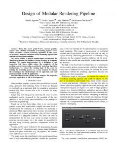
Figure 1. Rendering engine block diagram Our research [Her04, Zem03] performed up till now resulted in the following concept of “striping”. The basic idea of this algorithm is to let the FPGA handle one horizontal stripe (a portion of the framebuffer covering several subsequent scan-lines) and render particles coming from the particle source into it. The particle source ensures particles come in a predefined order – with increasing y (i.e. vertical) coordinate. The stripe is then moving vertically across the frame-buffer by one line, rendering all particles and covering the whole frame-buffer area. Each move-down of the stripe consists of two steps: a) flushing the top-most line to the global framebuffer, and b) re-using it as a fresh bottom line for the next stripe position. To avoid delays caused by flushing of the finished lines, more color-buffer lines are allocated, allowing the rendering to proceed continually – see Figure 2.
2. RENDERING ALGORITHM
As each particle generally affects large number of pixels, it is desirable to have the frame and depth buffers distributed in several memory banks that can be accessed in parallel in order to parallelize the rendering process. To achieve efficient parallelization of rendering, it must be ensured that the particles affect minimum possible number of words in the memory banks and at the same time that the affected words are as uniformly as possible distributed in all memory banks. The constraints in the FPGA led us to the decision to use 8 memory banks with 8 bits for
Figure 2. The striping algorithm The presumption of the particles being sorted into groups by one coordinate and in a particular order is not too restrictive. The particles can be sorted into this form easily, provided the system contains a memory buffer large enough to store all the particles in the scene. Such memory does not necessarily have to provide high-bandwidth random access, and it does not need to be connected to the FPGA closely as each of the particles is needed by
the FPGA during the rendering only once and in a defined order. This memory can contain particle lists for each line of the frame buffer and sort incoming particles into them (see Figure 3). The process of sending the particles into the rasterizing FPGA will be started after receiving all particles of the scene. +, ,
)
*.
*
/.
particles (ellipses) may result in an architectural design similar to the one shown in Figure 5, based on a “particle writing machine” in Figure 4.
-
0.
"
*
(
#
Figure 3. Sorting particles by their y-coordinate
Figure 4. Particle writing machine utilizing the striping
Incorporating these mechanisms together with a rasterization pipeline rasterizing the shapes of the
The particle writing machine embodies the following operations:
operation write-particle
arguments x, d, color, shape
description Writes particle of given properties (d=depth, shape – encoded into a small number of bits by a suitable algorithm). Note that the y coordinate is determined by the state of the writing machine – the number of calls to the new-line operation. Disposes the “oldest” line of the stripe, starts flushing into the framebuffer, and activates the next free spare color-buffer line. Starts a new frame, skips y first lines without particles (filled with background color). This operation may well exist without the argument, only starting a new frame – it would be then followed by appropriate number of subsequent calls to new-line.
new-line start-at-line
y
Table 1. Basic operations of the particle writing machine
$ $
& '(
(
"
"%
Figure 5. Over-all rasterizer design, consisting of a particle source incorporating the rasterization process, of the particle memory sorting particles by their y-coordinate and the striping writer
3. EXPERIMENTAL HARDWARE IMPLEMENTATION
For the hardware implementation, FPGA Xilinx Virtex E 300 has been used. In the future, Virtex II is planned to be used instead. Hardware design programmed in the FPGA consists of particle reader/writer, pixel reader/writer, frame and depth buffers and the viewing engine. FPGA input frequency is 100 MHz, but for the major part of the design, 50 MHz is used. Accessing time to the SRAM (used as a video-RAM) is 15 ns. This memory and ADV 478 chip (D/A converter and palette memory) are placed outside the FPGA. There is also 16 MB SDRAM placed at the board used by the DSP. This SDRAM runs at 100 MHz. The Display Refresh Subsystem takes care about correct viewing of an image placed in the SRAM and its writing into this memory. Every pixel clock period, data are read from the memory (address is the counter automatically incremented every pixel clock cycle). Meanwhile, shared data bus is put to the third state at the side of FPGA, so that data from the memory could be read by the ADV 478 chip. Pclk rising edge ensures the data on this bus to be converted to analog format suitable for a TV or a monitor. #
*3
2
( ,
*3 #
+
.
# 4
(
#5 678
# (
,
.
,
95
"%
Figure 6. Experimental implementation block scheme Between every two pixels read for the TV out, it is possible to place one read or write cycle from/to SRAM. Such cycle is used for reading the image to the DSP and writing pixels into the RAM. The writing requests come from two sources – pixel writer (pixels written directly from the DSP) and frame buffer of the particle writer. SRAM is organized as a two-bank video RAM in order to implement double-buffering: while writing an image to one bank, the second bank is being shown on the screen and vice versa. An extension to the striping particle writer concept as presented in section 2 is the Pixel Reader/Writer unit, which allows accessing the
SRAM frame-buffer directly from the DSP. It simply gets data and address from the DSP and writes to the SRAM through the viewing engine. This operation may be used for writing additional information to the screen. It is also possible to read the data from the memory, and e.g. store the image in the DSP controlled memory for future use. However, this means of access to the frame-buffer is meant primarily for debugging and testing purposes, it is not very fast, since any request through this port waits to be synchronized with monitor refresh and the particle writer. Functional description of the Particle Writer unit is described in the theoretical part of this article. Hardware implementation consists of few state machines using two groups of block RAMs – one for the frame buffer and one for the depth-buffer. #
# .
#
1 .
.
" ,
"2
Figure 7. Particle Writer When a particle description is sent from the DSP, it is processed by the register decoder. Base horizontal coordination is set to its position, and two counters are running to define the exact position of the current processed pixel. One counter runs from zero to maximum and displays the upper part of the particle. Second counter runs from maximum to zero and displays the lower mirrored part. Writing engines start writing reacting to the start write signal. While processing, data are read from the depth-buffer, and writing engines decide whether to write (both to the frame and the depth-buffer) or not by comparing the actual depth with the depth from the depth-buffer. Reading from the depth-buffer must start some cycles before the writing process due to the memory read latency. When the special code word is written by the DSP, writing is moved to the next line and flushing of the processed line is started – data from the BlockRAM are written to the SRAM through the viewing engine.
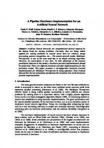
4. ACHIEVED RESULTS
The proposed algorithm was fully implemented on an experimental setup shown below in Figure 8, that uses the Camea DX6 board [Cam03]. Current maximal number of particles rendered by the FPGA is 5 million per second. This number comes out from
the clock period which is 20 ns, and the number of cycles required for showing one particle. One column of a particle is written in one period, and two periods are required for pre-reading the depth-buffer data. Totally 10 periods are 200 ns per particle. Of course, possibilities exist to improve the performance. Using more advanced FPGA chip (for example Virtex II) would lead into higher possible frequency (we assume at least 100 MHz). Another
possibility is to parallelize writing to the memory by setting the width of the data bus to the Block-RAMs from 8 bits to 32 bits. Extra logic for treating this situation would be needed, but speed-up ratio would be up to four. We could also avoid the depth-buffer reading latency by pipelining. Finally, we could show one particle in 2 clock cycles (10 ns), which means speedup up to 10 times from the current state to 50 million particles per second, still using standard offthe-shelf components.
Figure 8. Experimental setup displaying a medical data set
5. CONCLUSION
In this paper, a rendering system based on Xilinx Virtex E-300 FPGA and Texas Instruments C6711 DSP was described. The system implements a modern 3D point-cloud rendering algorithm and is fully functional. 3D point cloud graphics seems to be a concept of close future for visualization and realistic rendering, partially replacing the most common approach at the moment – triangle meshes. The proposed rasterization algorithm solves the rendering task including the visibility issues between the particles inside the FPGA in order to achieve high performance. A part of the projection phase is left to the host task being performed by the DSP. While this solution leaves space for further hardware acceleration, it was chosen as the best possible approach to test the concept.
Hardware implementation in the FPGA contains control subsystems treating read and write cycles of the video-RAM, pixel writer and the particle writer. The particle writer unit consists of eight pixel writers that write the data to the internal Block RAMs, the flushing unit that transfers the image to the video SRAM, and of the DSP bus interface. Current speed of particle drawing is 5 million per second. Changes that could increase this number up to 50 million still using currently available general purpose components are proposed. However, this implementation is considered to be rather a proof-of-concept than a final graphics acceleration solution. The Virtex II Pro Xilinx FPGA that is to come should allow further optimizations and may be ground for a graphical hardware challenging graphics equipment of desktop computers.
6. ACKNOWLEDGMENTS This work was partly supported by the “Rapid prototyping tools for development of HWaccelerated embedded image- and video-processing applications”, GA AV R, T400750408 grant.
7. REFERENCES
[Cam03] “DSP Accelerator Boards”, CAMEA, Ltd., (available at http://www.camea.cz/products/accelerators.cz.htm) [Her04] Herout, A, Zemcik, P: Animated Particle Rendering in DSP and FPGA. In: SCCG 2004 Proceedings, Bratislava, SK, 2004, pp 237-242, ISBN 80-223-1918-X [Gro02] Gross, M: “Point Based Computer Graphics”, Spring Conference of Computer Graphics 2002, Budmerice, Slovakia, 2002 [Mit03] Mitsubishi Electric Research Laboratories: “SURFELS - Surface Elements as Rendering Primitives, (available at http://www.merl.com/projects/surfels/) [Pfi00] Pfister, H, Zwicker, M, van Baar, J, Gross, M: Surfels: Surface Elements as Rendering Primitives. Proceedings of SIGGRAPH 2000, pp 335-342 [Ree83] Reeves, WT: “Particle Systems – A Technique for Modeling a Class of Fuzzy
Objects”, ACM Transactions on Graphics, Vol. 2, No. 2, April 1983 [Rus01] Rusinkiewicz, S: “QSplat: A Multiresolution Point Rendering System for Large Meshes”, Proceedings of SIGGRAPH 2001, USA, 2001 [TMS01] TMS3B0C6711, TMS320C6711B Floating point Digital Signal Processors, Texas Instru-ments, SPRS088B, September 2001, USA, 2001, (available at http://www.ti.com) [Vir01] VirtexTM 2.5V Field Programmable Gate Arrays, Xilinx, DS003-1 (v2.5), April 2, 2001, USA, 2001, (available at http://www.xilinx.com) [Wat93] Watt A.: 3D Computer Graphics, AddisonWesley, Wokingham, UK, 1993 [Zem02] Zemcik, P: “Hardware Acceleration of Graphics and Imaging Algorithms Using FPGAs”, SCCG 2002, Budmerice, Slovakia, 2002 [Zem03] Zemcik, P, Tisnovsky, P, Herout, A: “Particle Rendering Pipeline”, SCCG2003, Budmerice, Slovakia, 2003 [Zwi01] Zwicker, M, Pfister, H, van Baar, J, Gross, M: “Surface Splatting” In: Proceedings of SIGGRAPH 2001, ACM SIGGRAPH, Los Angeles 2001