Progress In Electromagnetics Research B, Vol. 63, 263–273, 2015
A Review on Reconfigurable Integrated Filter and Antenna Weng Yik Sam* and Zahriladha Zakaria
Abstract—In the past few years, several satisfying various objectives and designs of reconfigurable integrated microwave filter and antenna have been proposed for wireless communication systems. Several designs are new concepts and techniques, whereas others are inspired from previous works. The improvement concepts of these designs can be reviewed from this compilation of studies. This paper begins with an explanation of the reconfigurable filter, reconfigurable antenna and reconfigurable integrated microwave filter and antenna, followed by discussion on several designs in terms of size, measurement, performance and technology used. Among various designs, reconfigurable on planar structures are extensively used because of their simple design procedures and easy to tune on the desired frequency, bandwidth and attenuation. Most of the existing studies are focusing tunable on single element, i.e. either on filter or antenna side; however, it limits the tunable range and flexibility of the filtering antenna response. An alternative design of filtering antenna can be suggested to produce reconfigurable tuning capabilities on both microwave filter and antenna to produce overall good performance for multifunction operation in RF/microwave applications.
1. INTRODUCTION Traditional RF/microwave front-end wireless communication systems are designed for a fixed predefined operation and the main components in these systems such as filter and antenna also retain some fixed parameters such as frequency band, radiation pattern, bandwidth, attenuation, gain and polarization. However, modern technology such as cellular radio system, radar system, aircraft, satellite and Unmanned Airborne Vehicle (UAV) radar, and microwave imaging that requires flexibility to support a very large number of standards (e.g., UWB, UMTS, WLAN, Bluetooth, WI-Fi, WiMAX, etc.) to mitigate the strong interference signals and to cope with the changing environmental condition. Therefore, filters play important roles in many RF/microwave modern wireless application systems especially for separating and combining or selecting and rejecting signals at various frequencies [1]. However, the frequency spectrum as a resource is valuable and limited. This continues to challenge RF/microwave filters with ever more severe requirements such as low insertion loss, light weight, linear phase, high selectivity, small size and lower cost [2, 3]. Electronically reconfigurable tunable filters are attracting more interests for research and development due to their increasing importance in wideband radar, multiband systems and electronic warfare systems [4]. In general, based on various tuning elements used, tunable filters may be classified as semiconductor (varactor diode and P-I-N diode) tunable filters [5–9], piezoelectric transducer (PET) tunable filters [10–14], RF microelectromechanical systems (MEMS) tunable filters [15–17], and ferroelectric materials tunable filters [18–20]. A well-known problem for tunable filters is the variation of the bandwidth as the centre frequency is tuned. This is mainly due to the frequency dependence of the coupling networks. Several techniques have been addressed to overcome this problem; to achieve constant absolute bandwidth over a broad tuning range using different tuning elements. Received 25 August 2015, Accepted 6 October 2015, Scheduled 14 October 2015 * Corresponding author: Weng Yik Sam (
[email protected]). The authors are with the Centre of Telecommunication Research and Innovation (CeTRI), Faculty of Electronic and Computer Engineering (FKEKK), Universiti Teknikal Malaysia Melaka (UTeM), Hang Tuah Jaya 76100, Melaka, Malaysia.
264
Sam and Zakaria
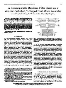
Tunable bandwidth is more challenging than frequency tuning and the design of an electronically reconfigurable filter with a wider bandwidth is much difficult than a narrow bandwidth in terms of tuning range and bandwidth control. There were some methods for the bandwidth controls in a tunable filter reported [21–23]. Figure 1 shows an example of fabricated tunable bandstop filter.
Figure 1. An example of fabricated tunable bandstop filter [22]. The nonlinear behavior of an electronically reconfigurable filter is dependent on the tuning element used. The use of MEMS and a piezoelectric transducer usually results in better linearity. Innovation in an electronically reconfigurable filter design can increase the functionality of the design and improve the performance as well as capability. The relatively low Q-factor of tuning elements can limit the implementation of higher-order and narrowband tunable filters. This is because, for a given Q-factor of the tuning structure and other losses associated with the circuit design, the insertion loss of a filter is increased with an increase of its order and a decrease of its bandwidth. As a result, the insertion loss of a higher-order with tunable element can be much larger for practical applications. In addition, the tuning range is limited to a higher-order than for a lower-order filter [24, 25]. The improvement of an electronically reconfigurable filters involves some trade-offs, such as the size of the filter and the complexity of the bias circuit, which added into these challenges. Table 1 shows the comparison of different tuning device technologies. Table 1. Comparison of different tunable device technologies [26, 27].
Tuning Technology
Tuning Speed
Quality Factor
Power Handling (mW)a
Power Consumption
Temperature Cost Sensitivity
P-I-N diode
ns
Rs ≈ 1 Ω
High
20–30 mA
Low
Low
Schottky diode
ns
Q ≈ 30–150
10–100
0
Low
Low
MEMS switch
µs
Q ≈ 50–400
100–1000
Negligible
Low
Lowb
Baruim-Strontium-titanate (BST)
ns
Q ≈ 30–150
20–200
Negligible
High
Low
Yttrium-iron-garnite (YIG)
ms
Q ≈ 500–2000
> 50–200
0.5–5 W
High
High
2. TUNABLE FILTER INTEGRATION Tunable microwave filters are critical to RF front-end design through the capability of single system to select multiple frequencies. For instance, such frequency agile filters provide military radars to scan a wide spectrum along a particular frequency band for electronic encounter measure (ECM) applications. Additionally, secure military communication systems such as the frequency hopping transceivers also require the implementation of RF tunable filters [28, 29]. The microwave filter tuning mechanism is classified into three major types: mechanical, magnetic and electronic [30]. Mechanically tunable filters are realized using the co-axial or waveguide resonators and have large power-handling and low insertion
Progress In Electromagnetics Research B, Vol. 63, 2015
265
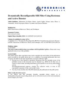
loss [31]. However, these tuned filters have slow tuning speed and often are large and more bulky for the application in modern integrated systems [32]. Magnetically tunable filters have been used extensively in microwave communication systems and have single crystal Yttrium-Iron-Garnet (YIG) spheres in the resonators that are tuned by changing the biasing current. The advantages of these filters are very high tuning range, low insertion loss, spurious free response and high quality factor (Q-factor). The disadvantages include size, power consumption, tuning speed and incompatibility in integrated systems [33, 34]. Electronically tunable filters typically employ variable capacitors, semiconductor diodes or RF MEMS switches that are controlled by applying a bias voltage. This provides the required variance to the capacitive or inductive loading in a resonator thereby electrically shifting the centre frequency of the filter. Advantages include high tuning range, compact size, fast tuning and compatibility to integrate with other front-end systems. However, the disadvantages involve lower filter performance parameters compared to magnetic or mechanically tuned filters [35, 36]. 3. PLANAR RECONFIGURABLE FILTERS This section describes filters using planar transmission lines that provide the advantage of a simple structure and easy to integrate with tuning elements (e.g., P-I-N diode, varactor diode and etc.). Planar transmission lines also allow flexible filter design in the structure due to the wide tuning range of coupling structures that can be realized in planar structure. Research shows that it is possible to change a loaded coupling filter’s characteristic from bandpass to bandstop by changing the RF MEMS switches DC bias voltage from 0 V to 12 V at centre frequency tuning of 0.77–1.10 GHz [21]. The filter was fabricated using 25-mil Duroid substrate (εr = 6.15, Rogers RT/Duroid 6006). A custom-switch bandstop open loop filter [37] working at approximately 10 GHz was demonstrated using 8 vanadium dioxide switches, which change from a semiconductor state to a metallic state when a DC bias voltage is applied to them. The filter was fabricated using two levels of photolithographic mask on a sapphire substrate and a wire bonding was used to connect the switches. Each switch adds a pole to the bandstop filter changing among the pre-selected configurations of bandwidth and centre frequency (fc). Wideband bandpass filters with reconfigurable bandwidths using stubs connected to P-I-N diodes were presented, with two pre-selected bandwidths when the P-I-N diodes are in the ON state or OFF state [38] as shown in Figure 2. In the ON state mode, about 35% fractional bandwidth (FBW) at 3 dB of the OFF state mode is reduced to 16%, whereas the insertion loss increased 4 dB at a centre frequency of 1.9 GHz. Ultra-Wideband (UWB) bandpass filters with reconfigurable bandwidths were presented with a notch band and wide upper stopband [39]. The insertion loss was constant around 1.5 dB and the bandwidth of notch band at 10 dB is changed from 5.2 GHz to 5.9 GHz. However, the response of the return loss is quite poor which is slightly just better than 10 dB.
Figure 2. Fabricated reconfigurable filter blocks with narrowband stubs [38].
266
Sam and Zakaria
In [40], a tunable combline filter using interdigital coupled capacitive and interresonator taps in low frequency (800 MHz) was presented. The parametric analysis was tuned from 0.15 mm to 0.9 mm to obtain the optimum response of the interresonator coupling structure. The simulated response of the return loss is better than 13 dB, an insertion loss of 1 dB with bandwidth of 22.5%. However, the capacitive-loaded resonator introduces its second harmonic at 1540 MHz which might interrupt the response on the design. On the other hand, a very high frequency tuning range of 16% was demonstrated with interdigital coupling structure from the tuning range of 784.92 MHz to 918.23 MHz in [41], but the return loss was very poor, slightly around 10 dB. The insertion loss gives good response at 9.0 V of 0.69 dB with compact structure of 27.8 mm × 16 mm. A quasi-elliptic ferroelectric filter at frequency tuning range of 2.4 GHz (33.6–36.0 GHz) and fabricated on benzocyclobutene (BCB) layer by using standard photolithography techniques [42]. The filter exhibits a moderate frequency tuning range of 9%. However, the insertion loss is high reaching about 6.2 dB and frequency and bandwidth also vary simultaneously. Moreover, this filter is tuned with ferroelectric capacitors, which need a high DC bias voltage of 30 V. A tunable bandpass filter with fmin at 0.58 GHz with bandwidth control was presented in [43]. It uses commercial varactor diodes (BB857) to change the frequency range and the bandwidth tuned between 115 MHz–315 MHz (12.6%–54.3% FBW). It showed the typical insertion losses of 1.53 dB and 1.19 dB for the narrow and wide passband responses respectively. In [44], an octave tunable two-pole bandstop filter for RF/microwave systems was presented. Two pole bandpass filter and varactor diodes are used to tune the frequency range from 0.56 GHz to 1.18 GHz with tuning ratio of 4.2 : 1. This design is useful to control the peak stopband attenuation and frequency selectivity. However, the manufacturing cost is high due to the complexity of the design as well as the alignment of the structure. A tunable centre frequency and bandwidth using varactor diodes tuned bandstop filters was proposed by [45]. This concept is suitable to be used in the adaptive receiver front-ends to eliminate co-site and foreign interferences. This design consists of a varactor-loaded transmission line resonator with odd symmetry which is coupled twice through the line as shown in Figure 3. This design is able to tune from the frequency range at 1.2 GHz–1.6 GHz and the bandwidth is tunable from 70 MHz to 140 MHz. Another design on tunable design using fixed-tuned and varactor-tuned microstrip was proposed by [46]. The fixed-tuned design is able to achieve a stopband rejection better than 50 dB with an upper passband that extends about 9 times of the fundamental frequency. The varactor-tuned bandstop achieves a 56% of centre frequency tuning range with passband extending up to 8.9 times from the lowest-tuned centre-frequency. This technique is theoretically possible to elimate all spurious that interfere the response. However, the gap of the design is difficult to fabricate due to the small size and
Figure 3. Designed two-pole bandstop filter (separated into three sections for illustration) [45].
Figure 4. Fabricated wide tunable combline bandpass filter with capacitance circuits [48].
Progress In Electromagnetics Research B, Vol. 63, 2015
267
the possible manufacturing cost is higher. [47] proposed intrinsically switched varactor-tuned filters and filter banks for RF switches applications. The concept uses the intrinsically switched works as bandstop filter with rejection of more than 50 dB with tunable range from 665 to 100 MHz. This design provides good rejection continuously and bandwidth in the band rejection. However, the insertion loss performance is poor and the design is quite complex to design due to the intrinsically switched filters layout. In [48], the high-Q tunable substrate integrated waveguide (SIW) resonator working from range 11.205 GHz to 11.748 GHz was demonstrated using the GaAs varactor diode and capacitances to tune the resonance frequency. The measurement shows the unloaded-Q of SIW resonator is 286–299 with a tuning range of 492 MHz and the phase noise of the SIW VCO is −93–95.6 dBc/Hz at 100 kHz offset for 455 MHz oscillating at X-Band range. Figure 4 shows the overall size of the SIW VCO design is 43 mm × 28 mm. The microstrip ring resonator based on bandpass filters [49] operates at K-band was demonstrated using P-I-N diodes to obtain high stop attenuation, steep roll-off and low insertion loss. The return Table 2. Summary of tunable microstrip filters of several researchers.
Ref.
Topology
Tuning Type
Tuning element
DC bias (V)
Resonant Frequency (GHz)
Insertion loss (dB)
Tuning range
Area, mm2
[21]
Coupled-Line
B
RF MEMS
12
0.78
1.9
-
-
[37]
Split Ring Resonators (SRR)
C
VO2 switch
-
9.0
-
5.5%
56
[38]
Coupled-Line and stub
B
P-I-N diode
-
1.9
4.1
50%
1200
[39]
Ring and stub
A
-
-
68.5
< 1.5
6.7 %
308
[40]
Combline
A
-
-
0.8
1
22.5%
245
[41]
Interdigital
C
GaAs Varactor diode
9
0.92
0.69
16%
445
[42]
Coplanar-waveguide
C
BST capacitor
30
50
7.6
8.8%
3
[43]
Coupled-Lines and stub
C
Varactor diode
28
0.75
1.53
54.3%
1250
[44]
Combline
C
Varactor diode
30
1.18
8
4.2%
240
[45]
Coupling
C
Varactor diode
-
1
-
50%
-
[46]
Combline
C
Varactor diode
-
0.951
0.5
56%
-
[47]
Coupled-line
C
GaAs varactor diode
20
0.8
5.0
122%
586
[48]
SIW resonator
C
RF MEMS switch
-
1.4
3.4
28%
-
C
P-I-N Diode
-
20
10
10%
-
[49] Squqre-Ring resonator
268
Sam and Zakaria
loss for low and high band is better than −10 dB and the bandwidth is around 1 GHz. However, the measurement shows poor insertion loss around −9 dB with the high and low band. Table 2 shows the summary of the different tunable filters into three groups (A): centre frequency tuning and constant bandwidth; (B) constant centre frequency and bandwidth tuning and (C) Simultaneously centre frequency and bandwidth tuning, along with their measurement performance. 4. MICROSTRIP PATCH ANTENNA Microstrip Patch Antennas are attractive due to their very light weight, low cost and conformability [50– 52]. These patch antennas can be integrated with any microstrip feed networks or printed stripline and active elements. Since the mid 1950’s, the radiation properties of microstrip structures have been used generally in a group of an array of configurations. The conventional patch antennas are bulky in size and the manufacturing cost is quite expensive. Microstrip patch antenna based on photolithography data is seen as engineering penetrates [51–54]. For better performance applications such as radar, aircraft, mobile phone and military communication, they
Table 3. Key literature on microstrip patch antenna. Ref. Year
[50]
[51]
[52]
[53]
2011
2013
2013
2014
Scholar(s)/ Researcher(s)
Focus of study
Ismail et al.
Investigations of P-I-N diode switch on reconfigurable antenna at frequency 3.0 GHz. The results give a better performance in term of return loss and current distribution. However, the measurement shows there is a frequency shift to the right about 100 MHz from the origin frequency.
Sun et al.
A simple design has been proposed to bias the varactor. Good radiation patterns are achieved in 2.4 GHz and 3.4 GHz. However the efficiency of antenna is quite low which at range of 70% for simulation while for measurement up to 50%.
Pujari et al.
Circular patch antenna is capable of tuning between an X-band of 6.5 GHz to 11.6 GHz with 2 different sub-bands. Tuning element is using varactor diode to tune the centre frequency from lower band to higher band. However, the measured return loss of tuning is poor, which around 6–14 dB for 6.5 GHz to 8.2 GHz range.
Mansoul et al.
A reconfigurable antenna is presented for high performance U-NII band radios covering three sub-bands (5.15 GHz– 5.35 GHz), (5.47 GHz–5.725 GHz) and (5.725 GHz–5.825 GHz). An inverted U fed with switches was introduced to allow the adjustment of desired band and bandwidth. However, the measured return loss for sub-band 3 is slightly shifted toward the high frequency compared to the simulated result.
[54]
2014
Mansoul et al.
[55]
2014
Gupta et al.
A selective frequency-reconfigurable antenna is capable of switching between a wide band of 2.63 GHz–3.7 GHz and four different sub-bands, which allows adjusting its bandwidth to select a suitable sub-band. However, the measured bandwidth for sub-band 2 is large about increment up to 50% from the simulated result. A compact ultra-wideband (UWB) reconfigurable antenna with 7 switches is presented with bandwidth of 2.54 GHz to 11.71 GHz and return loss of < −10 dB. Three narrowband, one dual-band and one triple band are introduced in this antenna as well. The overall size of the antenna is just 40 × 40 mm2 . However, the performance of the average return loss is poor, which around 10 dB level of the measurement results.
Progress In Electromagnetics Research B, Vol. 63, 2015
269
are very useful since they can be manufactured using a standard printed circuit board (PCB) method with lower radiation efficiency with a narrow bandwidth. Microstrip patch antenna is the most favorite device researched in the antenna design by most researchers [53]. The literature reviews are summarized based on the previous background studies of antenna design. However, most of the researchers focus on certain particular interest in the microstrip patch antenna design. The antenna review is summarized in Table 3. 5. RECONFIGURABLE INTEGRATED FILTER AND ANTENNA (FILTENNA) The integration concepts in various applications especially in the microwave field have become a recent interest of many researchers. The most current interest in the integrated filter and antenna provides a broad form of research [56]. Few researchers have explored on the integrated tunable filter with microstrip patch antenna. Table 4 shows the key literature on integrated filter and antenna design. Table 4. Key literature on integrated filter and antenna. Ref. Year
[56]
2012
Scholar(s)/ Researcher(s)
Focus of study
Al-Husseini et al.
Design of filter antennas with reconfigurable bandstop is proposed for the ultra-wideband cognitive radio (UWB-CR) systems. However, the bandwidth is large, nearly up to 1 GHz that will filter out the response from the ultra-wideband range of the measurement results.
[57]
2012
Al-Husseini et al.
Design a simple single-port frequency-tunable filter antenna for cognitive radio systems. This design uses a single varactor diode (SMV 1405) to tune filter’s frequency over a 0.5 GHz wideband. However, the measured response shows the reflection coefficient has been biased toward lower frequency when SMT capacitor is used during the experimental works.
[58]
2012
Tawk et al.
Size reduction for reconfigurable filtenna with overall size of 30 mm × 30 mm. This gives a large bandwidth from simulated and measured up to 40% with tunable frequency range from 6.16 GHz–6.47 GHz.
Qin et al.
Design a microstrip monopole antenna with a reconfigurable at 10 dB impedance bandwidth for cognitive radios application. A varactor diode is used to tune the operating frequency from 3.8 GHz–6.9 GHz with a narrow bandwidth.
Mansoul et al.
The design is suitable for high performance Unlicensed National Information Infrastructure U-NII band 5.15 GHz–5.825 GHz) or in one of its three subbands (5.15 GHz–5.35 GHz, 5.47 GHz–5.725 GHz and 5.725 GHz–5.825 GHz) either entirely. This design allows adjusting the desired frequency band and bandwidth, four horizontal slots with switches at the ground plane. However, there is a slightly increment bandwidth on the measurement results about 100 MHz at frequency range of 5.725 GHz–5.825 GHz.
[59]
[60]
2014
2014
Several studies were reviewed and each presented unique ideas for developing reconfigurable integrated filter and antenna. Based on the designs, the most sought-after characteristics of filters at present are a miniature size, freedom in selecting frequencies, low insertion loss and easy to design. Various methods have been developed for reconfigurable filter and antenna, but majorities of them are focused on a single tunable element either in the filter or in an antenna. Furthermore, tunable on single element will limit the tunable range on reconfigurable filter and antenna. Although, recent studies show large tunable capabilities on the reconfigurable filter and antenna, but some varactor diodes requires
270
Sam and Zakaria
a large amount voltage (up to 30 V) to produce a high tunable range of the reconfigurable filter and antenna. Therefore, an electronically reconfigurable microwave filter with microstrip patch antenna is suggested in order to improve the performance of the return loss, bandwidth and tuning range of the filter and antenna. This can be implemented by using semiconductor elements (P-I-N diode or varactor diode) on the design on both elements (filter and antenna). Hence, it will utilize the tuning range on both elements: filter and antenna to provide the flexibility of the filtering antenna response. Therefore, this new integration of electronically reconfigurable on both microwave filter and antenna is expected to produce a good response and as well as to provide an alternative solution for multifunction operation in RF/microwave applications. 6. CONCLUSION This paper has presented a review on reconfigurable integrated filter and antenna of various types of filter and antenna; the recent advances and its application in reconfigurable filters and antenna have been described and discussed. Among the various designs reviewed in this paper, most of the researchers tend to favor a microstrip structure. This structure is easy to fabricate, light, low in manufacturing cost and easy to integrate with any planar structure. Although recent studies show that microstrip structure is capable of reducing antenna size, but to produce a wider and flexible tuning range with low power and low loss is currently a big issue. This review is helpful in understanding the development trends of microwave filters. It aims to produce a reference for research interest in improving the reconfigurable integrated filter and antenna design to achieve better overall performance and compact size for multifunction operation applications. ACKNOWLEDGMENT The author would like to thank UTeM and the MyBrain15 program for sponsoring this study. The author would also like to thank UTeM for sponsoring this work under the eScience Fund MOSTI, 06-01-14-SF0103. REFERENCES 1. Zakaria, Z., N. Omar, A. R. Othman, M. S. Jawed, A. Ismail, A. Salleh, and W. Y. Sam, “Recent trends on dual- and triple-band microwave filters for wireless communication,” Australian Journal of Basic and Applied Sciences, Vol. 7, No. 10, 235–243, 2013. 2. Hong, J. S., Microstrip Filters for RF/Microwave Application, 2nd Edition, 1–2, Wiley, New Jersey, 2011. 3. Jarry, P. and J. Beneat, Design and Realizations of Miniaturized Fractal RF and Microwave Filters, Wiley, New Jersey, 2009. 4. Hong, J. S., “Reconfigurable planar filters,” IEEE Microwave Magazine, Vol. 10, No. 1, 73–83, 2009. 5. Hunter, I., “Theory and design of microwave filters,” The Institution of Electrical Engineers, London, 2001. 6. El-Tanami, M. A. and G. M. Rebeize, “Corrugated microstrip coupled lines for constant absolute bandwidth tunable filters,” IEEE Transaction on Microwave Theory Techniques, Vol. 56, No. 5, 1137–1148, 2008. 7. June, P. S. and K. M. Rebeiz, “Low-loss two-pole tunable filters with three different predefined bandwidth characteristics,” IEEE Transactions on Microwave Theory Techniques, Vol. 56, No. 5, 1137–1148. 8. Zhang, X. Y., Q. Xue, C. H. Chan, and B. J. Hu, “Low-loss frequency-agile bandpass filters with controllable bandwidth and suppressed second harmonic,” IEEE Transactions on Microwave Theory Techniques, Vol. 58, No. 6, 1557–1564, 2010.
Progress In Electromagnetics Research B, Vol. 63, 2015
271
9. Peng, W. W. and I. C. Hunter, “A new class of low-loss high-linearity electronically reconfigurable microwave filter,” IEEE Transactions on Microwave Theory Techniques, Vol. 56, No. 8, 1945–1953, 2008. 10. Blondy, P., C. Palego, M. Houssini, A. Pothier, and A. Crunteanu, “RF-MEMS reconfigurable filters on low loss substrates for flexible front ends,” Proceeding Asia-Pacific Microwave Conference (APMC), 1–3, Bangkok, 2007. 11. Reines, I. C., C. L. Goldsmith, C. D. Nordquist, C. W. Dyck, G. M. Kraus, T. A. Plut, P. S. Finnegan, F. IV. Austin, and C. T. Sullivan, “A low loss RF MEMS Ku-band integrated switched filter bank,” IEEE Microwave Wireless Components Letters, Vol. 15, No. 2, 74–76, 2005. 12. Yang, G. M., O. Obi, G. Wen, and N. X. Sun, “Design of tunable bandpass filters with ferrite sandwich materials by using a piezoelectric transducer,” IEEE Transactions on Magnetics, Vol. 47, No. 10, 3732–3735, 2011. 13. Wan, G.. C., J. Zhang, J. H. Zhou, X. F. Yin, and M. S. Tong, “Electromagnetic analysis of tunable bandpass filters with a magnetodielectric perturber,” Antenna and Propagation Society International Symposium (APSURSI), 1397–1398, Memphis, TN, 2014. 14. Jung, D. J., J. N. Hansen, and K. Chang, “Piezoelectric transducer-controlled tunable hairpin bandpass filter,” IEEE Electronics Letters, Vol. 48, No. 8, 440–441, 2012. 15. Zhang, N., Z. L. Deng, and F. Sen, “CPW tunable band-stop filter using hybrid resonator and employing RF MEMS capacitors,” IEEE Transactions on Electron Devices, Vol. 60, No. 8, 2648– 2655, 2013. 16. Safari, M., C. Shafai, and L. Shafai, “X-band tunable frequency selective surface using MEMS capacitive loads,” IEEE Transactions on Antenna and Propagation, Vol. PP, No. 99, 1–9, 2014. 17. Joshi, H., H. H. Sigmarsson, M. Sungwook, D. Peroulis, and W. J. Chappell, “High Q fully reconfigurable tunable bandpass filters,” IEEE Transactions on Microwave Theory and Techniques, Vol. 57, No. 1, 3525–3533, 2009. 18. Kato, A., K. Nakatsuhara, and Y. Hayama, “Switching operation in tunable add-drop multiplexer with si-grating waveguides featuring ferroelectric liquid crystal cladding,” Journal of Lightwave Technology, Vol. 32, No. 22, 4464–4470, 2014. 19. Chun, Y. H., J. S. Hong, B. Peng, T. J. Jackson, and M. J. Lancaster, “BST varactor tunable dual-mode filter using variable Zc transmission line,” IEEE Microwave and Wireless Components Letters, Vol. 18, No. 1, 167–169, 2008. 20. Ghalem, A., F. Ponchel, D. Remiens, and T. Lasri, “A 3.8 GHz tunable filter based on ferroelectric interdigitated capacitors,” IEEE International Symposium on the Applications of Ferroelectric and Workshop on the Piezoresponse Force Microscopy (ISAF/PFM), 252–256, Prague, 2013. 21. Cho, Y. H. and G. M. Rebeiz, “Two- and four-pole tunable 0.7–1.1 GHz bandpass-to bandstop filters with bandwidth control,” IEEE Transactions on Microwave Theory and Techniques, Vol. 62, No. 3, 457–463, 2014. 22. Xiang, Q. Y., Q. Y. Feng, X. G. Huang, and D. H. Jia, “A 2.285–3.195 GHz electrical tunable bandstop filter with constant absolute bandwidth,” IEEE International Wireless Symposium (IWS), 1–4, X’ian, 2014. 23. Dmitry, K., T. VIacheslav, and B. Alexandra, “A method to design lumped-element tunable bandpass filters with constant absolute bandwidth,” European Microwave Conference (EuMC), 335–338, Rome, 2014. 24. Vendik, I., O. Vendik, V. Pleskachev, A. Avishchev, and R. Wordenweber, “Design of tunable ferroelectric filters with a constant fractional bandwidth,” IEEE MTT-S International Microwave Symposium Digest, 1461–1464, Phoenix, AZ, 2001. 25. De-Paolis, R., F. Coccetti, S. Payan, A. Rousseau, M. Maglione, and G. Guegan, “Microwave characterization of ferroelectric thin films for novel compact tunable BST filters,” European Microwave Integrated Circuits Conference (EuMIC), 460–463, Nuremberg, 2013. 26. Rebeiz, G. M., K. Entersari, I. Reines, S. J. Park, M. A. El-Tanani, A. Grichener, and A. R. Brown, “Tuning in to RF MEMS,” IEEE Microwave Magazine, Vol. 10, No. 6, 55–72, 2009.
272
Sam and Zakaria
27. Lourandakis, E., R. Wiegel, H. Mextorf, and R. Knoechel, “Circuit agility,” IEEE Microwave Magazine, Vol. 13, No. 1, 111–121, 2012. 28. Hunter, I. C., L. Billonet, B. Jarry, and P. Guillan, “Microwave filters — Applications and technology,” IEEE Transactions on Microwave Theory and Techniques, Vol. 50, No. 1, 794–805, 2002. 29. Bhana, V., T. Stander, and S. Sinha, “A frequency agile switched delay line slow-wave BiCMOS filter,” 23rd International Conference Radioelektronika (RADIOELECTRONIKA), 45– 49, Pardubice, 2013. 30. Uher, J. and W. J. R. Hoefer, “Tunable microwave and millimeter-wave bandpass filters,” IEEE Transactions on Microwave Theory and Techniques, Vol. 39, No. 4, 643–653, 1991. 31. Vincent, G. H., “Modern microwave ferrites,” IEEE Transactions on Magnetics, Vol. 48, No. 3, 1075–1104, 2012. 32. Arnold, C., J. Parlebas, and T. Zwick, “Reconfigurable waveguide with variable bandwidth and center frequency,” IEEE Transactions on Microwave Theory and Techniques, Vol. 62, No. 8, 1663– 1670, 2014. 33. Zhang, X. F., X. Han, M. Balinskiy, and H. X. Tang, “Compact, widely tunable, half-lambda YIG oscillator,” IEEE International Frequency Control Symposium, 1–3, Baltimore, 2012. 34. Yang, G.. M., J. Wu, J. Lou, M. Liu, and N. X. Sun, “Low-loss magnetically tunable bandpass filters with YIG films,” IEEE Transactions on Magnetics, Vol. 49, No. 9, 5063–5068, 2013. 35. Wang, X. G., Y. H. Cho, and S. W. Yun, “A tunable combline bandpass filter loaded with series resonator,” IEEE Transactions on Microwave Theory and Techniques, Vol. 60, No. 6, 1569–1576, 2012. 36. Christodoulou, C. G., Y. Tawk, S. A. Lane, and S. R. Erwin, “Reconfigurable antennas for wireless and space applications,” Proceedings of the IEEE, Vol. 100, No. 7, 2250–2261, 2012. 37. Biugye, D., A. Crunteanu, O. Massague, J. C. Champeaux, A. Catherinot, A. Velez, J. Bonache, F. Martion, and P. Blondy, “Applications of vanadium dioxide (VO2)-loaded electrically small resonators in the design of tunable filters,” Proceedings of the 40th European Microwave Conference, 822–825, Barcelona, 2010. 38. Miller, A. and J. S. Hong, “Wideband bandpass filter with reconfigurable bandwidth,” IEEE Microwave Theory and Techniques, Vol. 58, No. 12, 3936–3944, 2010. 39. Zhu, H. and Q. X. Chu, “Ultra-wideband bandpass filter with a notch-band using stub-loaded ring resonator,” IEEE Microwave and Wireless Components Letters, Vol. 23, No. 7, 341–343, 2013. 40. Martin, A., M. El-Sabbagh, and B. Mohajer-Iravani, “A miniaturized ultra-wideband microstrip filter using interdigital capacitive loading and interresonator tapped-in coupling,” IEEE International Conference on Ultra-Wideband (ICUWB), 95–98, Syracuse, 2012. 41. Suo, G., X. Guo, B. Cao, B. Wei, X. Zhang, Z. Shang, and G. Zhang, “Loss low tunable superconducting dual-mode filter at L-band using semiconductor varactors,” IEEE Microwave and Wireless Components Letters, Vol. 24, No. 3, 170–172, 2014. 42. Hu, J., B. Lacroix, K. Choi, Y. Wang, A. T. Hunt, and J. Papapolymerou, “Ka- and U-band tunable bandpass filters using ferroelectric capacitors,” IEEE Transactions on Microwave Theory and Technique, Vol. 59, No. 12, 3068–3075, 2011. 43. Luo, X., S. Sun, and R. B. Staszewski, “Tunable bandpass filter with two adjustable transmission poles and compensable coupling,” IEEE Transactions on Microwave Theory and Techniques, Vol. 62, No. 9, 2003–2013, 2014. 44. Anand, A., Y. Liu, and X. Liu, “Substrate-integrated octave-tunable combline bandstop filter with surface mount varactors,” IEEE International Wireless Symposium (IWS), 1–4, X’ian, 2014. 45. Guyette, A. C., “Varactor-tuned bandstop filter with tunable centre frequency and bandwidth,” iIEEE International Conference on Wireless Information Technology and Systems, 1–4, Honolulu, 2010. 46. Guyette, A. C., “Design of fixed- and varactor-tuned bandstop filters with spurious suppression,” IEEE European Microwave Conference (EuMC), 288–291, Paris, 2010.
Progress In Electromagnetics Research B, Vol. 63, 2015
273
47. Guyette, A. C., “Intrinsically switched varactor-tuned filters and filter banks,” IEEE Transaction on Microwave Theory and Techniques, Vol. 60, No. 4, 1044–1056, 2012. 48. Sekar, V. and K. Entesari, “A half-mode substrate-integrated-waveguide tunable filter using packaged rf mems switches,” IEEE Microwave and Wireless Components Letters, Vol. 22, No. 7, 336–338, 2012. 49. Rohrdantz, B., V. Schmidth, and A. F. Jacob, “Microstrip ring resonator based frequency reconfigurable band-pass filters at K-band,” 20th International Conference on Microwaves, Radar and Wireless Communication (MIKON), 1–4, Gdansk, 2014. 50. Ismail, M. F., M. K. A. Rahim, and H. A. Majid, “The investigation of PIN diode switch on reconfigurable antenna,” IEEE International RF and Microwave Conference (RFM), 234–237, Seremban, Negeri Sembilan, 2011. 51. Sun, X. L., S. W. Cheung, and T. I. Yuk, “Dual-band monopole antenna with frequency-tunable feature for WiMAX applications,” IEEE Antennas and Wireless Propagation Letters, Vol. 12, No. 1, 100–103, 2013. 52. Pujari, P., K. Vyras, and B. K. Sharma, “Design and simulation of circular patch antenna for multiband application of X-band using varactor diodes,” Conference on Advance in Communication and Control Systems (CAC2S), 140–144, DIT Dehradun, 2013. 53. Mansoul, A., F. Ghanem, and M. Trabelsi, “A frequency reconfigurable antenna for high performance U-NII band radios,” The 8th European Conference on Antennas and Propagation (EuCAP 2014), 1893–1895, The Hague, 2014. 54. Mansoul, A., F. Ghanem, M. R. Hamid, and M. Trabelsi, “A selective frequency-reconfigurable antenna for cognitive radio applications,” IEEE Antennas and Wireless Propagation Letters, Vol. 13, No. 1, 515–518, 2014. 55. Gupta, C., D. Maheshwari, R. K. Saraswat, and M. Kumar, “A UWB frequency-band reconfigurable antenna using switchable slotted ground structure,” 4th International Conference on Communication Systems and Network Technologies (CSNT), 20–24, Bhopal, 2014. 56. Al-Husseini, M., A. Ramadan, A. El-Hajj, and K. Y. Kabalan, “A tunable filter antenna for cognitive radio systems,” Antenna and Porpagation Society International Symposium (APSURSI), 1–2, Chicago, 2012. 57. Ramadan, A. H., M. Al-Husseini, K. Y. Kabalan, A. El-Hajj, Y. A. Tawk, C. G. Christodoulou, and J. Costantine, “A narrowband frequency-tunable antenna for cognitive radio applications,” The 6th European Conference on Antenna and Propagation (EUCAP), 3273–3277, Prague, 2012. 58. Tawk, Y., M. E. Zamudio, J. Costantine, and C. G. Christodoulou, “A cognitive radio reconfigurable filtenna,” The 6th European Conference on Antenna and Propagation (EUCAP), 3565–3568, Prague, 2012. 59. Qin, P.-Y., Y. J. Guo, and F. Wei, “Frequency agile monopole antenna using a reconfigurable bandpass filter,” IEEE Antennas and Propagation Society International Symposium (APSURSI), 1250–1251, Memphis, 2014. 60. Mansoul, A., F. Ghanem, and M. Trabelsi, “A frequency reconfigurable antenna for high performance U-NII band radios,” The 8th European Conference on Antennas and Propagation (EUCAP), 1893–1895, The Hague, 2014.