A Run-Time System for Partially Reconfigurable FPGAs: The case of STMicroelectronics SPEAr board George CHARITOPOULOS a,b,1 , Dionisios PNEVMATIKATOS a,b , Marco D. SANTAMBROGIO c , Kyprianos PAPADIMITRIOU a,b and Danillo PAU d a Institute of Computer Science, Foundation for Research and Technology-Hellas, Greece b Technical University of Crete, Greece c Politecnico di Milano, Dipartimento di Elettronica e Informazione, Italy d STMicroelectronics, Italy Abstract During recent years much research focused on making Partial Reconfiguration (PR) more widespread. The FASTER project aimed at realizing an integrated toolchain that assists the designer in the steps of the design flow that are necessary to port a given application onto an FPGA device. The novelty of the framework lies in the use of partial dynamic reconfiguration seen as a first class citizen throughout the entire design flow in order to exploit FPGA device potential. The STMicroelectronics SPEAr development platform combines an ARM processor alongside with a Virtex-5 FPGA daughter-board. While partial reconfiguration in the attached board was considered as feasible from the beginning, there was no full implementation of a hardware architecture using PR. This work describes our efforts to exploit PR on the SPEAr prototyping embedded platform. The paper discusses the implemented architecture, as well as the integration of Run-Time System Manager for scheduling (run-time reconfiogurable) hardware and software tasks. We also propose improvements that can be exploited in order to make the PR utility more easy-to-use on future projects on the SPEAr platform. Keywords. partial reconfiguration, run-time system manager, FPGA
1. Introduction Reconfiguration can dynamically adapt the functionality of hardware systems by swapping in and out hardware tasks. To select the proper resource for loading and triggering hardware task reconfiguration and execution in partially reconfigurable systems with FPGAs, efficient and flexible runtime system support is needed [1],[2]. In this work we present the realization of the Partial Reconfiguration (PR) utility on the SPEAr prototyping development platform, we integrate the Run-Time System Manager (RTSM) pre1 Corresponding Author: George Charitopoulos: Technical University of Crete, Greece; E-mail:
[email protected].
sented on [3] and check the correctness of the resulting system with the use of a synthetic task graph, using hardware tasks from a RayTracer application [4] executed in parallel with a software edge detection application. Our main contributions are: (i) an architecture that achieves partial reconfiguration (PR) on the SPEAr’s FPGA daughter-board, based on a basic DMA module provided by [4], (ii) the integration of a state of the art RTSM on the SPEAr side, and (iii) concurrent execution of HW and SW applications on the SPEAr platform. STMicroelectronics distributes the SPEAr development platforms with an optional configurable embedded logic block; this block could be configured at manufacturing time only. With our approach, the configurability can extend even after the distribution of the board to the customers with the use of PR on the FPGA daughter-board. Despite the fact that PR has been done many times before the realization on the specific SPEAr board is done for the first time. The next section presents the specifics for the SPEAr development board and its FPGA daughterboard, and the architectural details for the realization of PR on the SPEAr platform. Section 3 offers a performance evaluation of the actual SPEAr-FPGA system and Section 4 offers insights on the limitations faced during this effort and the advantages of PR realization on the SPEAr platform. Finally Section 5 concludes our work.
2. The SPEAr Platform and Partial Reconfiguration In this section we describe the technology specifics and induced limitations of the SPEAr platform, and its Virtex-5 FPGA daughter-board; we also present the architecture implemented for the realization of partial reconfiguration. 2.1. SPEAr Development board The SPEAr platform is equipped with an ARM dual-core Cortex-A9@600MHz with two level of caching and 256MB DDR3 main memory connected to the ARM processors through an 64-bit AXI bus. The board also supports several external peripherals to be connected using standard interfaces such as Ethernet, USB, UART, etc. By means of the auxiliary EXPansion Interface (EXPI) present on the board, it is also possible to plug in dedicated boards to expand the SOC with customizable external hardware. The interconnection’s communication is driven by the AHBLite protocol. The choice of the EXPI interface and of the AHBlite protocol lets designers attach custom acceleration boards and interface them quickly, thanks to the simplicity of the AHBLite protocol. The overall interconnection scheme of the system is summarized in Fig. 1. The AXI bus supports two data channel transfers, where the read and write can be done simultaneously. On the other hand the AHB has only one data channel and read and write operations cannot be overlapped, leading to lower copmpared to AXI. Moreover, the internal interconnection crossbars that convert from AHB to AXI bus increase the overall transfer latency and constitute a further bottleneck to the board’s performance when multiple transmissions from main memory and the external components are happening simultaneously. Specifically the measured transfer of the AHB bus is 1 MB/s.
Figure 1. Interconnection scheme of the SPEAr platform.
2.2. The Xilinx Virtex-5 daughter-board The FPGA board ships an auxiliary bidirectional interface (EXPI) to connect external peripherals. Since the SPEAr board was designed for functional prototyping, the EXPI interface provides a single AHBLite bus with both master and slave interfaces on the board side, thus requiring external components to implement these same interfaces. The AHBLite protocol uses a single data channel for communications, so that it is impossible to receive and send data at the same time, e.g., to have a continuous stream between memory and computing cores. This is a major limitation in exploiting hardware acceleration, considering the low frequency (166 MHz) of the channel and the DMA burst size (1KByte). The SPEAr board uses a Virtex-5 LX110 FPGA, a device series that support partial reconfiguration. A most common and efficient way to achieve PR on a Xilinx FPGA is by accessing the Internal Configuration Access Port (ICAP). While usually Virtex-5 boards provide a number of I/O peripherals (such as SD card Reader, UART interface, LEDs, switches, etc), the SPEAr board supports I/O is only through the EXPI. This poses a limitation to the designer, who has to transfer the reconfiguration data from an external memory connected to the SPEAr, e.g. a USB stick, to the FPGA, using a slow DMA interface.
Figure 2. Main buses and components used in the communication between the SPEAr and the FPGA.
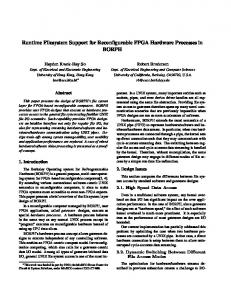
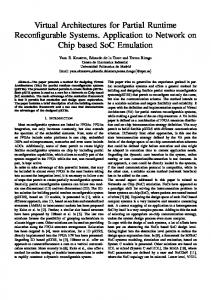
Fig. 2 shows the architecture involved in data transfer from the DMA memory to the AHB bus and finally to the reconfigurable regions (RR), which accommodate the hardware cores for the application, the ICAP component. Besides the two reconfigurable regions/cores, we also use an ICAP component for reconfiguration. 2.3. Partial Reconfiguration on the SPEAr platform In order to perform a data transfer from the SPEAr board to the FPGA and vice versa, we need to analyze the actions performed on the two ends (SPEAr board, FPGA). On the one end is the SPEAr board, which upon booting, loads a Linux Kernel/OS and opens a bash console on the host PC, accessed by the UART port. Through this command line a software driver, that enables the communication with the AHB bus is loaded. The driver was provided to us by [4], provides the user with simple functions that initialize and perform DMA transfers functions: • fstart_transfer: Used to initiate the transfer and also informs the DMA controller which RR/core the data are being transferred to or from. • fwait_dma: Used to inform the OS when the dma transfer has ended. • fwrite_buffer and fread_buffer: Used from the user write and read the buffers accommodating the dma transfer data. The other end of the communication is the FPGA. The FPGA implements a DMA controller as well as input and output data FIFOs for the cores. In order for the different RR/cores to be able to understand whether the incoming data refers to the specific core the DMA implements a handshake master/slave protocol with valid data and not valid data signals for each RR/core. The user, through the command console initiates the transfer, deciding from which RR/core needs data, or to which RR/core data are sent. Upon initiating a transfer between the SPEAr and the FPGA the user sets an integer parameter on the fstart_transfer arguments, which is the selection of the core the transfer refers to. To achieve PR the first decision made was how the reconfiguration would be done from the FPGA side. Xilinx offers several primitives in order to use PR on an FPGA. The most common, as mentioned is the ICAP controller located on the fabric’s side, provides the user logic with access to the Virtex-5 configuration interface. Then the way the ICAP will be accessed has to be determined. One option is the implementation of a MicroBlaze micro-processor, which sends the reconfiguration data to the ICAP through the PLB bus with the use of Xilinx kernel functions. The second more complex option of accessing the ICAP is via a FSM, which will control directly the ICAP input signals and the ICAP’s timing diagrams. In the second case the ICAP primitive is instantiated directly inside the VHDL source code. The first option is easier in the simple case. However in our case synchronization issues arise between the clocks of the ARM processors (SPEAr), PLB bus (FPGA), MicroBlaze (FPGA) and ICAP (FPGA). Thus the use of a MicroBlaze processor was deemed impossible. To implement the second option we implemented a FIFO that would store 15 words at a time, once this limit was reached these 15 words to the were sent to the ICAP, after applying the bitswapping technique mentioned on the Xilinx ICAP User Guide [5]. The architecture of the ICAP component we created is shown in Fig. 3. To control the ICAP component behavior we created a custom FSM, that depending on the current state of the system, produces the correct sequence of control signals responsible for the device reconfiguration. The FSM state diagram is shown in Fig. 4.
Figure 3. The ICAP component architecture.
Figure 4. The FSM controlling the reconfiguration process.
During the initialization state, the system waits for new data to appear on the DMA FIFO, specifically the data have to be about the ICAP core, i.e. the fstart_transfer has the appropriate core selection. Once new data arrive, the FSM begins to write new data to the intermediate FIFO, upon completion the ICAP component produces an interrupt, sent directly to SPEAr. If for any reason the DMA transfer stops, the FSM enters a wait for new data state, until new data appear again in the DMA FIFO. Then the FSM begins the reconfiguration phase by sending data to the ICAP controller, as soon as all the data, residing on the intermediate FIFO have been transferred, the ICAP component produces another interrupt. The value of this interrupt depends on whether or not this reconfiguration data transfer is the last or not. If it is the interrupt produced informs the SPEAr for the reconfiguration ending point, if not, the interrupt denotes the ending of an intermediate data transfer. While the reconfiguration process is active, this FSM prohibits other cores on the FPGA to perform a data transfer through the DMA, this is necessary to ensure the validity of the reconfiguration process. Finally, when the reconfiguration ends the ICAP component resets the newly reconfigured region, as dictated by the Xilinx user guides. The interrupt codes for the three interrupts are: • Interrupt FIFO_IS_FULL=15 • Interrupt ICAP_TRANSFER_END=13
• Interrupt RECONFIGURATION_END=12 By implementing all the above, the PR utility was enabled on the Virtex 5 FPGA daughter-board, via the SPEAr board. Also due to the fact that we do not use the slow software functions that perform reconfiguration when using the MicroBlaze microprocessor, we can achieve high reconfiguration speed. However this advantage is hindered by the slow DMA transfers necessary for transferring the bitstream, containing the reconfiguration data from the USB memory to the FPGA.
3. Performance Evaluation: A realistic scenario To provide a performance evaluation for the PR design we have created, we use two different applications from the field of image processing. The first application is a simple Edge Detection application, run exclusively on SW, the second is a RayTracer application [4] that runs also in software but switching its operation to hardware accelerators implemented on the FPGA. The point of using both this applications is to observe how the RTSM would cope with the increasing workload, of having to manage a hardware and a software application. The Edge Detection application is rather simple and consists of 5 (sub)tasks: Gray Scale (GS), Gaussian Blur (GB), Edge Detection (ED), Threshold (TH) and a final Write Image (WR) task. Tasks execute in succession, and each task passes its results to the next one. In order to achieve some level of parallelism we split the processed image in 4 quadrants that can be processed independently. This way each Edge Detection task must run 4 times before the task is considered as complete. The RayTracer application starts from a description of the scene as a composition of 2D/3D geometric primitives. The basic primitives that are supported by the algorithm are the following: triangles, spheres, cylinders, cones, toruses, and polygons. Each of these primitives is described by a set of geometric properties such as, for example, the position in the scene, the height of the primitive or the rays of the circles composing the primitive. In our case we consider only three of the available primitives, the sphere, the torus, and the triangle, because for these primitives we had available the HW implementation. The logic utilized by each of the three HW cores is shown at Table 1, the results shown here are the produced by the PlanAhead Suite. Table 1.: Summary of the logic resources used by the HW cores. Core Sphere Torus Triangle
LUT 7,051 5,466 6,168
FF 4,763 3,372 3,432
DSP 15 18 24
BRAM 2 2 4
It is clear that the critical resource are the DSPs. In order to have regions that can accommodate all the application cores we have to have at least 24 DSP modules present at each region. However Virtex 5 LX110 has only 64 available DSPs, which limits our design to just two Reconfigurable Regions. The RayTracer application does not solely run on hardware, it has a software part that runs on the SPEAr board. In order to display Partial Reconfiguration we created hardware implementations for the Sphere and
Triangle. This was done in order to place-and-swap these two tasks in the two different regions, while parallel execution takes place. Another choice would be to create partial bitstreams for all the RayTracer primitives and have only one RR. Another static region could be present according to the DSPs limitation. This static region could accommodate one of the primitives while the reconfigurable one could swap between the other two. We choose to run the experiment with two regions instead of one in order to so how the management of multiple hardware regions is handled better by the RTSM deployed. The RTSM used to test the offloading of hardware tasks on the FPGA is also able to manage and schedule SW tasks [4], with the use of thread create functions. The threads run in parallel accessing different parts of the processed data. While this works perfectly for the Edge Detection application, the RayTracer application access same data throughout the SW part of the application, hence the RTSM had to be extended. To achieve the desired functionality we replaced the thread creation functions by fork operations that create copy image of the RTSM application. This way we can create images of the RTSM and then switch the execution to another thread/application, thus enabling the parallel access of the data. The penalty of forking the application is non-observable, since it is masked, with the execution of hardware tasks on the FPGA and partial bitstreams transfers. Once the fork is completed the application immediately begins its hardware execution. In total we perform 4 fork operations. One more alteration we had to make was to synchronize the access of the different processes/threads on the DMA engine. It is easy to understand that any attempt of parallel execution is hindered by the fact that only one process at any time can have access on the DMA transfer engine. To achieve that a semaphore was created that the different RayTracer tasks must hold in order to access the DMA. This semaphored locks only the critical section of the RayTracer code, i.e. the DMA transfers achieved with the fstart_transfer, fwrite/fread_buffer and fwait_dma instructions. This operation from the hardware side is quite simple, since each core has its own input and output FIFOs then no mixing of input/output data would occur. However the same fast switch between processes accessing the DMA engine cannot be done while reconfiguration is in progress. This is because the reconfigured region while it undergoes reconfiguration could produce garbage results that could override other valid results the other region produces. The scheduling structure contains the scheduling decision made by the RTSM, such as all the needed information for the placement and the type of the task executed. It is an argument to the reconfiguration function in order to denote the correct bitstream to be reconfigured. The executable of the RayTracer is customized in order to offer the all the possible combinations of task/region a task can be executed into. The arguments passed to the execvp() function through the args[] array specify the core we want to execute -s for the sphere, and -t for the triangle, and an integer specifying the reconfigurable region the core will be executed into. Algorithm 1 shows the pseudo-code used to fork different processes. This code is added in the RTSM task creation section. Since the SPEAr’s resources are quite limited, we could not exploit all the abilities and the fine grain resource management offered by the RTSM deployed. Thus the built-in Linux scheduler that perform time-slicing scheduling was also used. In order to execute in parallel the two applications we created a merged task graph. For the RayTracer ap-
Algorithm 1 Spawn new RayTracer Task Require: Scheduling structure sem_wait(sem); //P operation reconfiguration(st); sem_post(sem); //V operation char *args[]= ”./stRayTracer”, ” − s”, 1, (char∗)0; child_pid1 = fork(); if child_pid1 < 0 then print f ("Fork error"); else {child_pid1 = 0} execvp(”./stRayTracer_sphere_RR1_triangle_RR2”, args); end if plication we created a synthetic graph consisting of four tasks, each task corresponding to a different HW core. The resulting task graph is shown in Fig. 5.
Figure 5. The application’s merged task graph. Edge Detection tasks are executed in SW, RayTracer tasks are executed in HW.
The first and last tasks are dummy tasks that synchronize the start and finish of the two applications. The RayTracer tasks are either an Sp. or a Tr., corresponding to either a sphere primitive or a triangle primitive. Each RayTracer task produces a different image with the name of a primitive and the region the task was executed in, e.g. sphere_RR1.ppm. In order to display better the advantages offer by PR we consider the tasks Sp.1 and Sp.2, which are two instances of the same sphere task that must run on region 1 and region 2 respectively, thus forcing a reconfiguration process to swap the placed tasks. If this differentiation was not done then the RTSM would reuse the already present on the FPGA, sphere bitstream, without the use of reconfiguration. The experiments verified the correctness of the PR architecture from section 3 and the scheduling decisions made by the RTSM, were in accordance with the simulations made before the actual experiment. The limited resources in terms of processor cores offered by the SPEAr board forced us to use the Linux time-slicing scheduler. If more cores were available then the applications could run in truely parallel fashion: the 4 instances of the Edge Detection task are independent from each other and the two RayTracer tasks run in parallel with a semaphore protecting the critical DMA resource.
Our PR design was compared with a static implementation of the two RayTracer cores. The static design executes only the RayTracer part of the task graph in Fig. 5, without the use of reconfiguration. Also the static design is not optimized to perform the exchange of the DMA engine between different processes. The overall execution of four RayTracer tasks (2 spheres, 2 triangles) is approximately 2 minutes and 8 seconds. Our design with the use of PR and the RTSM scheduling offers the same execution time. However the Edge Detection application finished its execution much earlier than the RayTracer one, the separate measured execution time for the Edge Detection application was 26.721 ms. The reconfiguration overhead is masked with the SW execution of the Edge Detection application, also in compared to the application execution time the overhead is negligible. The measured throughput for the reconfiguration process through the slow DMA bus was measured at 1.66MB/s.
4. Limitations & PR Advantages Despite the use of hardware accelerators and partial reconfiguration, no speed-up was achieved; this is due to the specific application used coupled with the limitations of the SPEAr and FPGA boards. • No external memory directly connected to the FPGA. This was a huge limitation we had to overcome. An external memory could limit the communication needed between the SPEAr and the FPGA, thus making the reconfiguration and the execution of HW tasks, much faster. Given the example of a Zynq Board the rate, for transferring data from an external DDR memory is 400MB/s which is 400x [?] compared to the current solution offered by SPEAr. • The SPEAr board can connect to several peripherals, which makes it extremely useful. Data received from these peripherals can be used by the FPGA but the DMA creates a huge bottleneck with its low speed, also the one way transfer limits the access to either read or write operation. • The RayTracer application used cannot achieve high execution parallelism. Applications that can have two or more regions processing data in parallel and then transferring results to the SPEAr board can mask the DMA overhead. Despite the limitations introduced by the two boards it is important to note that enabling partial reconfiguration offers many advantages: • Increased System Performance: PR provides the ability, to the user, to use more efficient implementations of a design for different situations. • Reduced Power Consumption: In power-constrained designs the user can simply download a more power- efficient version of a module, or a blank bitstream when the particular region of the device is not needed, therefore reducing the power consumption of the design. • Adaptability: Designs with the use of PR can adapt to changes in their environment, their input data or even their functionality. • Hardware Upgrade and Self Test: The ability to change hardware. Xilinx FPGAs can be updated at any time, locally or remotely. Partial reconfiguration allows the end user to easily support, service and update hardware in the field.
5. Conclusion This paper presents the work done in order to enable PR with the STMicroelectronics SPEAr development board. After making critical decisions regarding the development of the desired architecture, we tested our design with the parallel execution of two image applications. Due to severe limitationson the transfer of data from the SPEAr to the FPGA set by the device’s architecture, but also due to the specifics of the chosen application, no speed-up was measured between the static and the partially reconfigurable design, both executing at 3 minutes. However the user can work around the DMA transfer issue, with the use of large memory blocks residing on the FPGA to store the input data and then perform true parallel execution between the regions. The bottleneck of the device is the DMA engine which is extremely slow. However, the SPEAR prototyping embedded platform is a development board intended for feasibility studies, in particular to evaluate software systems developed for embedded platforms and how they could benefit from external hardware acceleration. Towards that goal, the support for partial reconfiguration can be very beneficial. The architecture we created is fairly generic and easy to be used in other R&D projects currently being developed on the STMicroelectronics SPEAr platform. In order to achieve better results with the applications used here and also future R&D projects a change should be made on the micro-electronic development of the board. Results show that the AHB-32 bus is extremely slow, plus the access to that bus is one way. A faster two way, concurrent read-write operations, on the DMA bus could offer better results and a better parallel solution than the one currently offered. Also another solution could be the integration of the FPGA on the SPEAr board itself, without the use of the EXPI interface, following the paradigm of Zynq ZedBoard platforms[4].
Acknowledgement This work was partially supported by the FP7 HiPEAC Network of Excellence under grant agreement 287759, and FASTER (#287804).
References [1] [2]
[3]
[4]
[5]
J. Burns, A. Donlin, J. Hogg, S. Singh, M. de Wit (1997): A Dynamic Reconfiguration Run-Time System. In: Proc. of the 5th Annual IEEE Symposium on Field-Programmable Custom Computing Machines. G. Durelli, C. Pilato, A. Cazzaniga, D. Sciuto and M. D. Santambrogio (2012): Automatic Run-Time Manager Generation for Reconfigurable MPSoC Architectures. In: 7th International Workshop on Reconfigurable Communication-centric Systems-onChip (ReCoSoC). G. Charitopoulos, I. Koidis, K. Papadimitriou and D. Pnevmatikatos (2015): Hardware Task Scheduling for Partially Reconfigurable FPGAs. In: Applied Reconfigurable Computing (ARC 2015) Lecture Notes in Computer Science Volume 9040, 2015, pp 487-498 . Spada, F.; Scolari, A.; Durelli, G.C.; Cattaneo, R.; Santambrogio, M.D.; Sciuto, D.; Pnevmatikatos, D.N.; Gaydadjiev, G.N.; Pell, O.; Brokalakis, A.; Luk, W.; Stroobandt, D.; Pau, D. (2014): FPGA-Based Design Using the FASTER Toolchain: The Case of STM SPEAr Development Board. In: Parallel and Distributed Processing with Applications (ISPA), 2014 IEEE International Symposium on , vol., no., pp.134,141, 26-28 Aug. 2014 http://www.xilinx.com/support/documentation/user_guides/ug191.pdf (Oct. 2012)